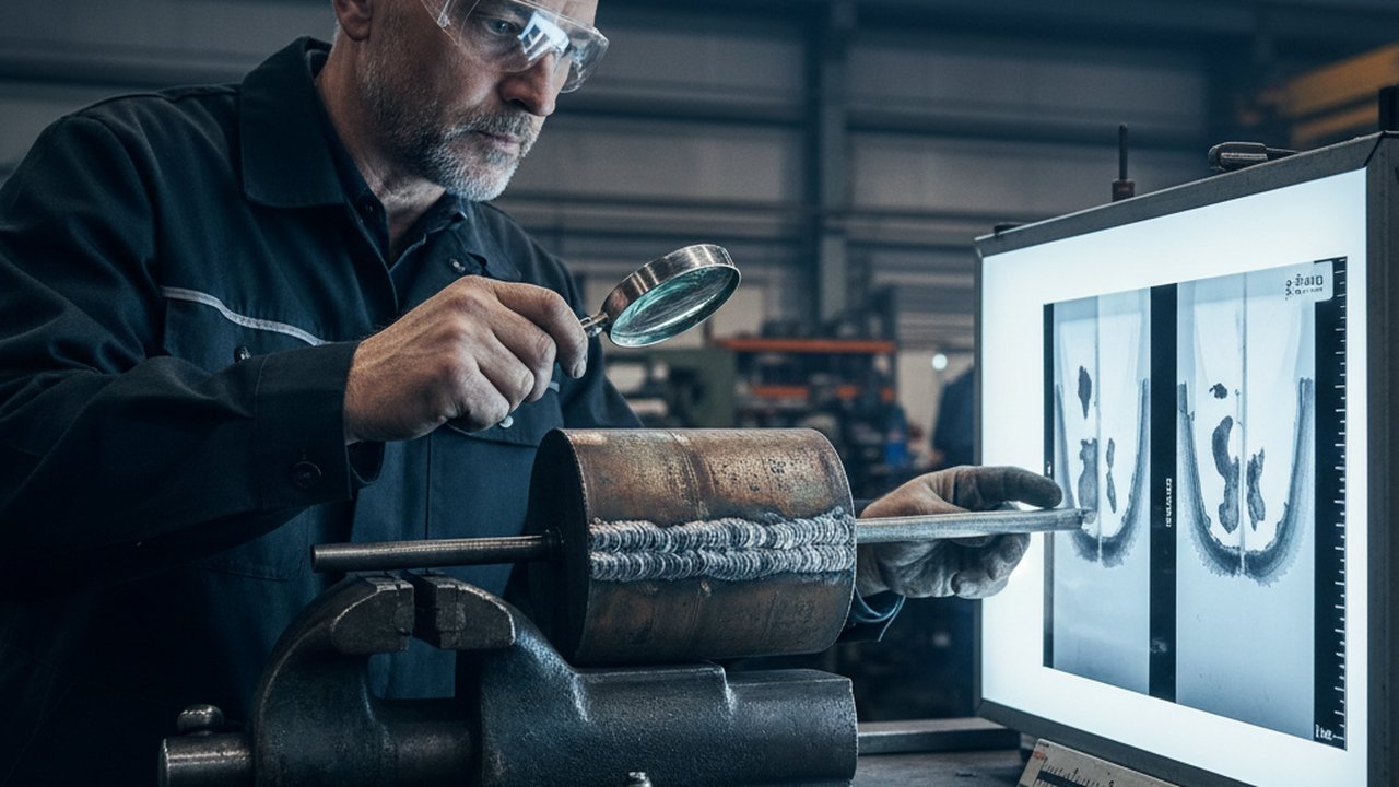
Arc strike repair welding is one of the most under-documented procedures in weld fabrication — yet an improperly repaired arc strike can nucleate fatigue cracks in dynamically loaded structures and generate audit findings under ISO 3834. This guide covers the complete repair sequence: initial assessment, grinding procedure, weld repair when grinding alone is insufficient, NDT verification, and traceable quality records.
For background on why arc strikes form and how ISO 5817 classifies them as imperfection 601, read the companion causes-and-acceptance-criteria post first.
Key Takeaways
- Arc strikes must be ground to sound metal before any weld repair — depositing a bead over an unground strike buries the hardened HAZ and any cracks beneath an uninspectable layer.
- Grinding alone is acceptable only when the base material has low hardenability, no cracks are detected visually, and post-grind wall thickness stays above the design minimum.
- Any bead deposited as part of a repair requires a qualified WPS under ISO 15614-1 or AWS D1.1 — repair welds are not covered by the original joint procedure.
- NDT after repair must match the criticality of the parent joint: magnetic particle or penetrant testing, plus a hardness traverse on hardenable steels.
- ISO 3834 requires every arc strike repair to generate a traceable record tied to the weld ID and the Inspection and Test Plan.
- A real-time welding monitoring system flags stray arc events as they happen — turning arc strike incidents from recurring defects into logged single-occurrence events.
Table of Contents
- Why Proper Repair Cannot Be Skipped
- Step 1 — Assess the Arc Strike
- Step 2 — Grinding Procedure
- Step 3 — When a Weld Repair Is Required
- Step 4 — NDT Verification After Repair
- Common Failure Modes and How to Avoid Them
- Documentation and ISO 3834 Traceability
- Frequently Asked Questions
Why Proper Repair Cannot Be Skipped
When the welding arc touches bare parent metal outside the joint, even for a fraction of a second, it melts a shallow pool a few millimetres wide. That spot cools at an extreme rate because the surrounding cold plate acts as an infinite heat sink — without preheat, without controlled heat input, and without filler. On carbon and low-alloy steels with a carbon equivalent (CEV) above roughly 0.40, the result is untempered martensite, locally very hard and brittle, with hardness values that can reach 450–600 HV.
The same hydrogen-assisted cold cracking mechanism described in EN 1011-2 operates here, concentrated in a spot nobody planned or inspected. Combined with residual stress from thermal contraction, the hardened zone is a classic crack initiation site under fatigue or impact loading. Failures in bridge, crane, and offshore structures have been traced to arc strikes that looked insignificant during fabrication. For a sense of how an unstable arc reads on camera, watch what a failing weld looks like in real time.
ISO 6520-1 classifies arc strikes as imperfection code 601. Under ISO 5817, they are not permitted at quality levels B and C. At level D they are acceptable only if parent metal properties are not impaired — a condition that is very difficult to demonstrate on hardenable steels without hardness testing. In practice, most fabricators working to structural, pressure, or transportation codes treat every arc strike as requiring documented repair regardless of quality level.
Step 1 — Assess the Arc Strike
Before reaching for the angle grinder, characterise the arc strike. Rushing into grinding without this assessment is a common source of under-repair or over-repair.
Identify base material and hardenability
Check the material certificate (EN 10204 3.1 or 3.2 test report) for the carbon equivalent. Steels with CEV below 0.40 are generally considered non-hardenable under welding thermal cycles; above 0.40, untempered martensite formation is likely. Austenitic stainless steels are immune to martensite but susceptible to sensitisation in the 450–850 °C range — on stainless, any heat input outside the qualified WPS heat input range is a concern.
If the material certificate is unavailable, treat the material as hardenable and apply the most conservative path: grind, MT or PT, hardness check.
Visual examination per ISO 17637
Examine the arc strike area under adequate illumination — minimum 500 lux per ISO 17637 — using the naked eye and a 5× or 10× loupe. Look for:
- Surface cracks radiating from the central melt zone, often hairline and only visible under good raking light.
- A bright, glazed melt spot surrounded by a discoloured heat-affected halo.
- Adjacent spatter particles, which indicate the arc may have dwelled long enough to create a deeper crater.
Any visible crack at this stage immediately elevates the repair to weld repair — grinding and NDT verification alone is insufficient to determine whether the crack extends below the visible surface.
The go/no-go assessment table
| Factor | Grinding only acceptable | Weld repair required |
|---|---|---|
| Base material CEV | Below 0.40 | Above 0.40 (or unknown) |
| Cracks on visual exam | None | Any crack visible |
| Post-grind wall thickness | Remains above design minimum | Would fall below design minimum |
| Governing code requirement | Level D non-critical | Levels B or C, or any dynamic load |
When in doubt, choose weld repair. Grinding that leaves a sub-surface crack is more dangerous than a visible defect because it passes visual inspection and is then inaccessible to surface NDT.
Step 2 — Grinding Procedure
Wheel selection and grinding parameters
Select an aluminium-oxide or zirconia-alumina wheel, 180–230 mm diameter, on an angle grinder. Never use carbon-contaminating cutting discs on stainless or nickel alloy components. For grinding:
- Remove the melt spot and the immediately adjacent heat-affected zone, typically 0.5–2.0 mm of total material depth.
- Blend the repair cavity smoothly with a minimum 4:1 taper: 4 mm of horizontal run for each 1 mm of depth. A sharp notch at the grind perimeter is a stress concentrator equivalent to the original defect.
- Prevent overheating: if the ground surface exceeds approximately 60 °C to the touch, pause and allow cooling or apply a compressed-air blast. Overheating during grinding can re-harden the surface by frictional heat.
- Finish the surface with a flap disc or fine abrasive paper to eliminate grinder scratches. A finish below Ra 12.5 µm is required before magnetic particle testing — coarse grinder marks generate magnetic leakage that masks real indications.
After grinding: thickness verification
Measure remaining wall thickness at the grind centre and at four radial points 10 mm away, using an ultrasonic thickness gauge or mechanical micrometer. All readings must exceed the drawing minimum wall thickness, including any applicable corrosion allowance. Record the measurements with instrument calibration reference.
If any measurement falls below the minimum: stop, mark the area, and proceed to Step 3 (weld repair) before any further grinding.
Step 3 — When a Weld Repair Is Required
A weld repair is required when grinding alone cannot achieve sound, adequately dimensioned parent metal — or when the governing code mandates it. Proceed as follows.
Qualified Welding Procedure Specification for repair
A dedicated repair WPS is mandatory. The original joint WPS does not cover repair welds: the joint geometry, access, and base-metal condition differ. Qualify a repair procedure under ISO 15614-1 or AWS D1.1. Key essential variables include:
- Base material group (ISO/TR 15608 group, or P-number in AWS).
- Filler material and welding process: match or exceed the base metal yield strength; use a low-hydrogen consumable (H5 or lower diffusible hydrogen per ISO 3690).
- Preheat and maximum interpass temperature, calculated from base metal composition and section thickness.
- Post-weld heat treatment (PWHT), if required by code for the base material and section.
The welder must be qualified per ISO 9606-1 for the repair process and position. Cross-reference the welder’s active qualification on the continuity record before allowing repair work.
Preheat and interpass temperature
Small repair beads lose heat faster than full production runs because the surrounding cold plate acts as a larger heat sink relative to the bead volume. Apply the same preheat temperature specified in the repair WPS, typically covering an area at least 75 mm in every direction from the repair zone. Preheat to the WPS minimum using an oxy-gas torch or electric resistance blanket; verify with temperature-indicating crayons or a calibrated contact thermometer.
Maintain the minimum interpass temperature between passes — allowing the repair zone to cool below the preheat minimum risks hydrogen cracking between deposits. On hardenable steels with CEV above 0.40, a dehydrogenation treatment at 200–250 °C for at least two hours immediately after welding, before any final cooling to ambient, significantly reduces the risk of delayed hydrogen-induced cracking.
Tempering bead technique
For carbon-manganese and low-alloy high-strength steels where post-weld heat treatment is impractical or not permitted by code (e.g., repair after pressure testing), a tempering bead sequence can refine the coarse-grained HAZ of earlier beads. The technique requires precise bead positioning so that the HAZ of the final covering bead reheats and tempers the HAZ of the previous bead into the 650–750 °C range. This requires a skilled welder following a procedure that specifies bead overlap geometry, travel speed, and heat input limits — it is not improvised fieldwork.
Step 4 — NDT Verification After Repair
NDT scope after arc strike repair must at minimum match the NDT specified for the parent joint. Do not reduce the NDT scope on the grounds that “it was only a small repair.”
Visual testing
Visual testing per ISO 17637 is always the first check. After grinding: confirm smooth profile, no under-flush grinding, no sharp notches, no adjacent damage from the grinder. After weld repair: confirm no undercut, no underfill, and no adjacent arc strikes introduced during the repair welding itself. The inspection lamp minimum is 500 lux at the surface; raking light at a low angle is essential for detecting surface cracks.
Magnetic particle testing and liquid penetrant testing
For ferritic steels, apply magnetic particle testing per ISO 17638 using a yoke or prods. MT detects surface and near-surface discontinuities that visual testing cannot resolve. Evaluate indications per ISO 23278. NDT personnel must hold ISO 9712 Level 2 or above for the method applied.
For austenitic stainless steel, aluminium, or titanium — where MT is not applicable — use liquid penetrant testing per ISO 3452-1. Apply fluorescent or colour-contrast penetrant with the appropriate dwell and developer times for the surface temperature and penetrant type. Evaluate per ISO 23277.
Hardness survey
On hardenable steels, perform a Vickers hardness traverse per ISO 6507-1 across the repair: measurements at the repair centre, at the fusion boundary, and at 1 mm intervals into the parent metal until three consecutive readings fall within the base metal hardness range. AWS D1.1 and EN 1011-2 both limit HAZ hardness to 350 HV10 for most structural steels. If the hardness survey shows values above the code limit, the repair WPS must be revised — typically by increasing preheat — and the procedure requalified before production repair work continues.
Common Failure Modes and How to Avoid Them
| Failure mode | Root cause | Prevention |
|---|---|---|
| Buried crack after welding over un-ground strike | Strike not removed before weld repair | Mandatory grinding to sound metal; verify with MT or PT before depositing any bead |
| Under-thickness after grinding | Melt zone deeper than visual estimate | Measure depth before grinding; compare against drawing minimum wall thickness |
| Delayed hydrogen cracking 12–48 h after repair | Insufficient preheat or no dehydrogenation treatment | Apply minimum preheat per WPS; carry out 200 °C/2 h dehydrogenation immediately after repair on hardenable steels |
| Additional arc strikes created during repair welding | Electrode contact outside the repair zone during positioning | Use run-on tabs; qualified welder; strictly controlled arc start location |
| MT false clear — cracks missed | Surface roughness from angle grinder | Achieve Ra below 12.5 µm before applying MT; correct yoke or prod spacing |
| Hardness limit exceeded in repaired HAZ | Preheat temperature too low for CEV and section thickness | Calculate minimum preheat per EN 1011-2 Annex C; requalify WPS if needed |
| Repair record not linked to weld ID | Post-repair documentation completed from memory | Pre-fill repair form with weld ID and location before work starts |
A real-time monitoring camera positioned to monitor weld paths captures stray arc events automatically — the arc-on timestamp and location are logged without relying on welders or supervisors to self-report the incident. This not only reduces the number of unreported arc strikes but also provides an objective evidence trail for the repair record.
Documentation and ISO 3834 Traceability
ISO 3834 Part 2 or 3 requires every repair — including arc strike repairs — to be traceable to the affected weld. The repair record must contain:
| Field | Required content |
|---|---|
| Component and weld ID | As on the weld map or ITP |
| Repair location | Distance from a fixed datum, face or root designation |
| Repair method | Grinding only — or weld repair with WPS reference number |
| Grinding wheel specification | Material, grit, maximum permissible surface speed |
| NDT method and result | VT, MT, or PT; indication-free confirmation; acceptance standard referenced |
| Hardness survey result | HV values, traverse location, code limit referenced |
| NDT inspector | Name, ISO 9712 method, level, certificate number |
| Welder (if weld repair) | Name, ISO 9606-1 process, position, certificate number |
| Date of repair | ISO 8601 format |
| Approving QC inspector | Name and signature |
This record attaches to the Inspection and Test Plan (ITP) for the affected component. Cross-reference the welder’s ISO 9606-1 continuity record to confirm the qualification range covers the repair process and position. For components requiring final dimensional report, include post-repair profile measurements in the same record.
A thermal monitoring system — one of several options across the Therness weld-monitoring hardware range — installed on the welding cell generates a time-stamped infrared heat log of every arc event on the part. That log can be referenced in the repair record as supplementary objective evidence of the repair thermal cycle — particularly useful when demonstrating to an auditor that preheat was maintained throughout the repair.
For context on the full quality management framework covering not just repairs but all welding quality requirements, see the ISO 3834 and EN 1090 audit checklist guide.
Frequently Asked Questions
When is grinding alone sufficient to repair an arc strike? Grinding is sufficient when the base material has a carbon equivalent below 0.40, visual inspection shows no surface cracks, and post-grind wall thickness remains above the drawing minimum. For hardenable steels, follow grinding with magnetic particle or penetrant testing to rule out sub-surface indications.
Do I need a qualified WPS to carry out an arc strike weld repair? Yes. Any bead deposited outside the original joint procedure constitutes a repair weld and requires a qualified Welding Procedure Specification per ISO 15614-1 or AWS D1.1, with the preheat and PWHT requirements appropriate to the base material and section thickness.
What NDT method is best after arc strike repair? Magnetic particle testing per ISO 17638 for ferritic steels; liquid penetrant per ISO 3452-1 for non-ferromagnetic materials. Add a Vickers hardness survey per ISO 6507-1 on hardenable steels.
Is an arc strike automatically rejectable under ISO 5817? At quality levels B and C, yes. At level D it is acceptable only if parent metal properties are not impaired — which requires hardness testing to demonstrate on hardenable steels. AWS D1.1 requires removal on all structural connections.
Can you weld directly over an arc strike without grinding first? No. This traps the martensitic HAZ and any cracks beneath the new bead, rendering them permanently inaccessible to surface NDT.
What is the maximum HAZ hardness allowed after repair? Both AWS D1.1 and EN 1011-2 specify 350 HV10 maximum for most structural steels. Confirm with the Vickers traverse described in Step 4.
How do I document an arc strike repair for ISO 3834? Complete the repair record table in the Documentation section above. Attach it to the ITP for the affected weld. Reference the welder’s ISO 9606-1 certificate range and the NDT inspector’s ISO 9712 certificate.
How deep can an arc strike be before a weld repair is mandatory? No universal depth threshold exists in standards. The decision hinges on whether grinding restores adequate wall thickness and leaves the remaining HAZ within hardness limits. If grinding would take wall thickness below the design minimum at any point, a weld repair is mandatory.
Detect Arc Strikes Before They Become Repair Jobs
Therness monitoring systems flag stray arc events in real time — your QC team gets an automatic record before the grinder comes out.
Book a demoTherness solution: Welding monitoring system — Every weld inspected in the cycle, with defect flags and the ISO 3834 / ISO 17635 evidence kept per weld.
Frequently Asked Questions
When is grinding alone sufficient to repair an arc strike?
Grinding is sufficient when the base material has low hardenability (carbon equivalent CEV below 0.40), no cracks are detected by visual examination, and post-grind wall thickness remains above the design minimum. On hardenable steels always follow with MT or PT to rule out sub-surface cracks.
Do I need a qualified WPS to carry out an arc strike weld repair?
Yes. Any weld bead deposited outside the original joint procedure — including a repair bead over a ground arc strike — is a repair weld and requires a qualified Welding Procedure Specification per ISO 15614-1 or AWS D1.1, including the preheat and post-weld heat treatment requirements applicable to the base material.
What NDT method is best after arc strike repair?
Magnetic particle testing (MT) per ISO 17638 is preferred for ferritic steels because it detects surface and near-surface cracks introduced by the rapid quench. Liquid penetrant testing (PT) per ISO 3452-1 is the alternative on austenitic or non-magnetic materials. A Vickers hardness survey per ISO 6507-1 is recommended on hardenable steels to confirm the repaired HAZ is within code limits.
Is an arc strike automatically a rejectable defect under ISO 5817?
At quality levels B and C, arc strikes are not permitted by ISO 5817. At level D they may be tolerated only if base material properties are unaffected — difficult to prove on hardenable steels without hardness testing. AWS D1.1 requires removal of arc strikes on all structural connections regardless of loading type.
Can you weld directly over an arc strike without grinding first?
No. Depositing a bead over an un-ground arc strike traps the hardened martensitic spot and any micro-cracks beneath the new bead, rendering them inaccessible to NDT. Grinding to sound metal must always precede any weld repair.
What is the maximum HAZ hardness allowed after arc strike repair?
Both AWS D1.1 and EN 1011-2 limit heat-affected zone hardness to 350 HV10 for most structural steels. ISO 15614-1 hardness traverses during WPS qualification verify this limit is achievable with the proposed preheat and interpass temperature regime.
How do I document an arc strike repair for ISO 3834 compliance?
Record the weld ID, repair location (distance from reference), repair method (grinding only or weld repair with WPS reference), grinding wheel specification, NDT method and result, inspector name and ISO 9712 certification level, and the date. Attach the repair record to the Inspection and Test Plan for the affected component.
How deep can an arc strike be before a weld repair is mandatory?
Standards do not define a universal depth threshold. The decision depends on whether grinding restores minimum cross-section and leaves the remaining HAZ within hardness limits. If grinding would reduce wall thickness below the drawing minimum, a weld repair is mandatory before grinding back to profile.