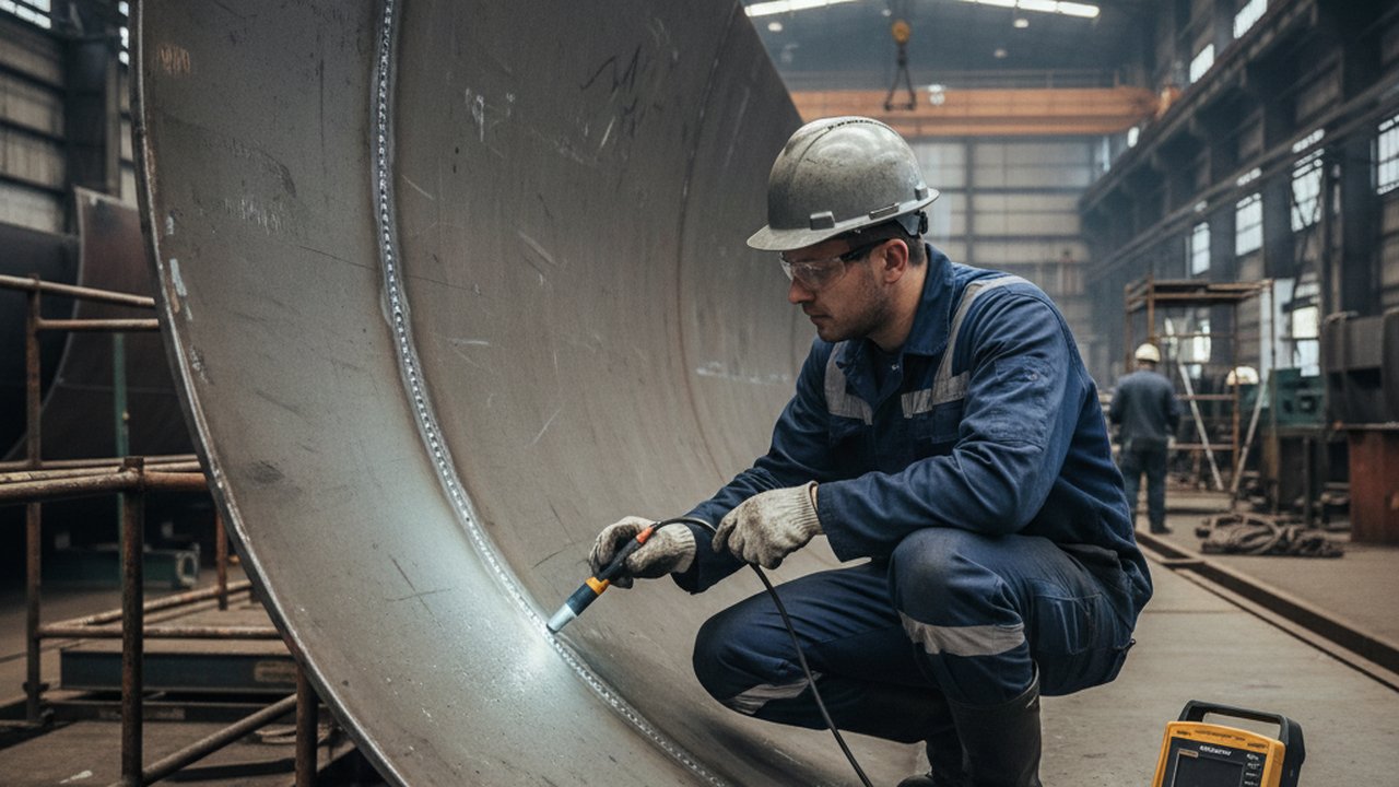
A pressure vessel weld passes visual inspection, the welder is qualified to ISO 9606, the WPS is countersigned, and the production radiograph still gets rejected at the customer’s incoming inspection. The reason almost always traces back to one document: ISO 17636. Most welding teams know it exists. Few read it cover to cover. The difference between Class A and Class B technique, between a 20 mm Selenium-75 setup and an X-ray tube at 220 kV, between an IQI at film side and source side — these are not academic distinctions. They are the line between a radiograph that gets accepted by Notified Bodies and one that costs the contract.
ISO 17636 is the international standard for radiographic testing (RT) of fusion-welded joints in metallic materials. It governs how the radiograph is produced, not how defects are judged — that boundary trips up many teams and is the first thing this guide will pin down. We will then walk the standard end to end: the two-part structure (film versus digital detectors), the Class A and Class B technique distinction, image-quality requirements, IQI selection, source-side rules, and the link to ISO 5817 and ISO 10675 acceptance criteria. We close with where real-time weld monitoring sits relative to RT — not as a replacement, but as the layer that prevents non-conformities from ever reaching the radiographic stage.
What Is ISO 17636?
| Question | Quick answer |
|---|---|
| What it governs | How the radiograph is made: source, geometry, IQI placement, technique class |
| What it does not govern | Whether an imperfection found in the image is acceptable — see ISO 10675 / ISO 5817 |
| How many parts | Two: Part 1 (film), Part 2 (digital — CR and DDA) |
| How many technique classes | Two: Class A (basic), Class B (improved sensitivity) |
| Who it certifies | Nobody — personnel certification is ISO 9712, Method RT |
ISO 17636 is split into two parts, and confusing them is the most common compliance error in audit observations.
- ISO 17636-1: Film technique. Conventional silver-halide film radiography. Still the dominant technique for one-off pressure vessels and code-stamped fabrications under ASME Section V where the inspection authority requires a tangible archival image.
- ISO 17636-2: Digital techniques. Computed Radiography (CR) using imaging plates, and Digital Detector Arrays (DDA) using flat-panel detectors. Image processing, dynamic range, basic spatial resolution, and signal-to-noise ratio replace film density and granularity.
Both parts share the same conceptual structure: source, geometry, image-quality indicator, acceptance of the image quality before the image content can be evaluated. The acceptance of defects in the weld is decided by a separate standard — typically ISO 10675-1 for general welds or the project-level standard the contract refers to (often ISO 5817 quality level B/C/D mapped to RT acceptance).
ISO 17636 governs whether the image is good enough to inspect. ISO 10675 (and ISO 5817) governs whether the welded joint is good enough to ship. A radiograph rejected under ISO 17636 cannot be evaluated under ISO 10675 — re-shoot first, judge second.
Class A vs Class B Technique — The Decision That Drives Everything
Both ISO 17636-1 and -2 define two technique classes:
| Class | Sensitivity | Typical use | Cost driver |
|---|---|---|---|
| A — Basic technique | Lower defect detectability | Statutory minimum for non-critical welds, supplementary inspection | Faster shoot, fewer constraints |
| B — Improved technique | Higher detectability of fine defects | Pressure vessels, nuclear, aerospace, critical structural welds, ASME code work | Tighter source size, longer SFD, stricter IQI requirements |
The difference is not philosophical. Class B mandates:
- A smaller effective source size (or higher source-to-film distance — SFD) so that geometric unsharpness drops.
- A higher minimum film density (in 17636-1) or higher signal-to-noise ratio and smaller basic spatial resolution (in 17636-2).
- Stricter IQI requirements — the smallest visible wire on the IQI must be at least one step finer than for Class A at the same penetrated thickness.
For fabrication shops, the cost gap between A and B is typically 40 to 80 percent more exposure time per shot once geometry constraints are honoured. That is why Class A is selected when the contract permits it — and why getting that contractual choice wrong, by accepting Class B for a project that priced Class A, is a direct margin loss.
Source Selection — X-ray vs Gamma
ISO 17636-1 Annex B and 17636-2 Annex B specify allowed sources by penetrated thickness:
- X-ray tubes — 100 to 450 kV typically. Best image quality, smallest focal spots (1 to 4 mm). Limited by infrastructure: shielded bay, three-phase power, cool-down cycles.
- Selenium-75 (Se-75) — half-life 119.8 days, energies around 100 to 400 keV equivalent. Sweet spot for steel 5 to 40 mm. Compact, field-portable, finer image than Ir-192.
- Iridium-192 (Ir-192) — half-life 73.83 days, energies up to 600 keV. Standard workhorse for steel 20 to 80 mm. Penalised on image quality versus Se-75 below 30 mm.
- Cobalt-60 (Co-60) — half-life 5.27 years, energies up to 1.33 MeV. Used for thick sections (50 to 200 mm steel). Significant geometric unsharpness penalty. Class B with Co-60 demands long SFD that often forces shooting in the open.
Choosing the source is not just about penetration. ISO 17636 imposes an upper energy limit for Class B at low thicknesses precisely because higher-energy gammas degrade contrast. A Class B radiograph of 12 mm steel shot with Ir-192 will fail IQI sensitivity even when the geometry is impeccable.
- 2–10 mm: X-ray ≤160 kV (Class B preferred; Ir-192 not allowed for B below ~10 mm)
- 10–40 mm: X-ray or Se-75 (Se-75 strongly preferred for Class B)
- 30–80 mm: Ir-192 standard; X-ray 300–450 kV for Class B critical work
- 80–200 mm: Co-60 or high-energy LINAC; expect shooting times in tens of minutes
Geometry, IQI, and the Numbers That Decide Acceptance
The image quality indicator is the heart of ISO 17636 compliance. Two IQI families dominate:
- Wire IQIs per ISO 19232-1. Six wires of stepped diameter, each set marked W1 to W19. Placed source side by default; film-side use is allowed only when source side is impossible, with stricter wire visibility requirement to compensate.
- Step/hole IQIs per ISO 19232-2. Used in jurisdictions where they are mandated by code (notably ASME-influenced supply chains).
ISO 17636-1 Tables B.4 and B.5 (for Class A and Class B respectively) map penetrated material thickness to minimum visible wire — for example, for steel at 25 mm penetrated thickness, Class B requires wire W11 (0.250 mm) visible source side. Missing W11 by one step (only W12 visible) is a non-conformity even if the radiograph looks perfectly readable.
Geometric unsharpness Ug is the second numerical gate. Defined as Ug = d × t / (SFD − t), where d is the source size, t is the object-to-film distance, and SFD is the source-to-film distance. ISO 17636-1 Table 4 caps Ug per thickness band — typical Class B at 50 mm penetrated thickness allows Ug ≤ 0.4 mm. Most non-conformities in audit come from operators leaving SFD short to save time and exceeding Ug without realising the IQI happens to still pass.
ISO 17636-1 specifies film density between 2.0 and 4.0 (Class B requires ≥2.3). ISO 17636-2 replaces this with SNRn (normalised signal-to-noise ratio) and basic spatial resolution SRb. A DDA panel shot at SNRn 130 with SRb 100 µm covers Class B at most thicknesses but fails for very thin sections — the spatial resolution requirement scales with the smallest IQI wire that must be detectable.
What Is ISO 17636-2? (Digital Radiographic Testing)
ISO 17636-2 is the digital half of the standard: it governs Computed Radiography (CR, a reusable imaging plate) and Digital Detector Arrays (DDA, a flat-panel detector), instead of silver-halide film. It keeps the same two-gate logic as Part 1 — image-quality test first, ISO 10675 / ISO 5817 defect judgment second — but swaps film density for the SNRn / SRb pair described above.
| CR (imaging plate) | DDA (flat-panel) | |
|---|---|---|
| Image ready | After a scanner readout | Immediately |
| Field portability | High — ships like film | Lower — panel and cabling |
| Typical fit | Site work replacing film, one-off shots | Shop-floor production RT, high shot count |
| Procedure qualification | Its own, not interchangeable with DDA | Its own, not interchangeable with CR |
CR and DDA are not interchangeable at the procedure level: a qualification written for one detector does not carry over to the other. For the applicability decision itself — whether a given shoot falls inside ISO 17636-2 at all — see the ISO 17636-2 scope guide.
How RT Acceptance Plugs Into ISO 5817
ISO 17636 stops at “is the radiograph evaluable.” The next document picks up: typically ISO 10675-1, which cross-references ISO 5817 quality levels B, C, and D. The flow is:
- Contract or project standard specifies ISO 5817 level (e.g. Level B for pressure vessels per PED).
- ISO 10675-1 maps that level into RT-specific acceptance limits per imperfection type — porosity area %, slag inclusion length, undercut depth, lack of fusion presence, cracks (always rejected for B and C).
- The radiograph is shot per ISO 17636 to a technique class that resolves the smallest acceptable defect for that quality level.
Each imperfection type in that chain is named and numbered in ISO 6520-1; see how two of the most common ones actually read on a radiograph in our entries on porosity and lack of fusion.
This three-layer chain is where supplier-customer disputes spawn. A Tier-2 fabricator shoots Class A, the radiograph is image-quality compliant, but the smallest porosity ISO 5817 Level B would reject is below the resolution Class A guarantees. The radiograph is accepted under ISO 17636 but the customer rightly rejects the weld because the inspection technique was insufficient for the contracted quality level.
For a side-by-side of how RT compares with VT, UT, and PAUT in a layered inspection strategy, see our welding inspection methods compared guide.
Personnel, Procedures, and the Audit Trail
ISO 17636 itself does not certify operators. That is delegated to ISO 9712 (general NDT personnel certification) — Level 1 prepares and shoots, Level 2 interprets and writes reports, Level 3 writes procedures and provides technical authority. RT-specific qualification is Method “RT” with sectoral endorsement (welds, castings, etc.).
A Class B radiograph with a perfect IQI signal is still rejected at audit if any of the following is missing:
- Written RT procedure approved by a Level 3, mapping job geometry to ISO 17636 technique parameters
- Operator certification card valid at the date of the shoot
- Calibration evidence for the source (gamma) or the X-ray tube
- Density/SNR measurement record per shot
- Traceability between the radiograph identifier, the weld ID, and the WPS used
Notified Body assessors under PED, the AD 2000-Merkblatt regime, or ASME stamp programmes will pull this trail at random. The most common gap, by a wide margin, is procedure approval not covering the actual penetrated thickness shot — Level 3s tend to write procedures for nominal thickness and miss the penetrated thickness when the joint geometry adds 20 to 40 percent.
Where Real-Time Monitoring Fits Around RT
RT is offline and after-the-fact. By the time a radiograph reveals lack of fusion in pass three of a multi-pass joint, the cap pass is on, the part has been moved, the welder has gone home. Repair is expensive precisely because RT detects defects after they are buried — watch how a defect forms mid-weld to see why catching it in-process changes the economics.
Real-time inline weld monitoring — thermal imaging, vision, acoustic — does not replace ISO 17636. It changes the economics of how often RT finds something. The argument is straightforward:
- RT remains the contractual acceptance test where the code or customer demands volumetric NDT
- Inline monitoring catches process drift (heat input, travel speed, arc length, shielding gas anomalies) that causes the defects RT later finds
- The combined effect is fewer RT rejections, less repair welding, faster cycle time, and a stronger audit narrative because every weld has process evidence even before the radiograph is shot
Therness builds inline thermal-monitoring systems specifically for this layered model. The output is not an alternative radiograph — it is a process record per pass that explains, with thermal evidence, why the radiograph is going to pass before the part reaches the RT bay.
For deeper coverage of NDT methods complementing RT, see how thermographic testing compares on welds.
ISO 17636 Implementation Checklist
Use this before signing off the next RT procedure or accepting an inbound radiograph:
- Is the technique class (A or B) explicitly stated in the contract and the RT procedure?
- Does the source choice (X-ray, Se-75, Ir-192, Co-60) match the penetrated thickness for the chosen class?
- Is the IQI type and minimum visible wire specified per ISO 19232-1, source side, with the film-side fallback rule documented?
- Is geometric unsharpness Ug calculated for the actual SFD used, not the nominal one?
- For digital (ISO 17636-2): are SNRn and SRb measured per shot and recorded in the report?
- Is the link to ISO 5817 / ISO 10675-1 quality level explicit, so the technique resolves the smallest defect that level rejects?
- Is the operator’s ISO 9712 RT Level 2 certification valid at the date of the shoot?
- Is the Level 3-approved procedure covering the actual penetrated thickness, not just the nominal plate thickness?
- Is upstream process evidence (thermal monitoring, parameter logs, welder ID) tied to the same weld ID as the radiograph?
If any answer is “no” or “unclear”, the audit risk is open regardless of how clean the radiograph looks.
Bottom Line
ISO 17636 is a precision instrument, not a checklist. The Class A vs Class B decision sets the cost and the detectability ceiling for the entire RT programme. The IQI rules and Ug limits leave little room for shortcuts: most rejected radiographs trace to source choice or geometry, not to operator skill. And the standard does not stand alone — it links to ISO 9712 for personnel, ISO 19232 for IQIs, ISO 10675-1 for acceptance, ISO 5817 for quality levels, and to whatever code (PED, ASME, EN 13445) the contract invokes.
Real-time monitoring does not replace any of this. It does shift the centre of gravity from after-the-fact detection to in-process prevention, which is where modern fabrication economics push every welding organisation that wants to stay competitive.
Bring process evidence to your RT programme
See how Therness inline thermal monitoring complements ISO 17636 radiography — fewer rejections, audit-ready process records per pass, faster cycle time. For continuous thermal monitoring on the shop floor, the HeatCam IR-C is a cylindrical thermal camera for fixed production-line installs — see how it compares to arc-visualization weld cameras.
Book a demo Explore inline weld monitoringTherness solution: Welding monitoring system — Every weld inspected in the cycle, with defect flags and the ISO 3834 / ISO 17635 evidence kept per weld.
Frequently Asked Questions
What is ISO 17636?
ISO 17636 is the ISO standard for radiographic testing (RT) of fusion-welded metallic joints. It specifies how the radiograph is produced — source, geometry, IQI placement, technique class — so the image is fit to inspect. It has two parts, film (Part 1) and digital detectors (Part 2), and it does not decide whether an imperfection is acceptable; that sits in ISO 10675 or ISO 5817.
What is ISO 17636-2 and how is it different from ISO 17636-1?
ISO 17636-2 covers radiographic testing with digital detectors — Computed Radiography (CR) and Digital Detector Arrays (DDA) — while ISO 17636-1 covers conventional film. Both parts share the same structure (source, geometry, IQI, Class A/B technique), but Part 2 replaces film density with signal-to-noise ratio (SNRn) and basic spatial resolution (SRb) as the image-quality checks.
What is the difference between Class A and Class B radiographic testing?
Class A is the basic technique: faster to shoot, fewer constraints, lower defect detectability. Class B is the improved technique: smaller source size or longer source-to-film distance and stricter IQI visibility, typically specified by the application standard for pressure vessels, nuclear, aerospace, and critical structural welds. ASME code radiography instead follows ASME Section V Article 2, which sets its own technique requirements rather than the ISO Class A/B split. Either way, the contract or the applicable code sets the class, not the operator on the day.