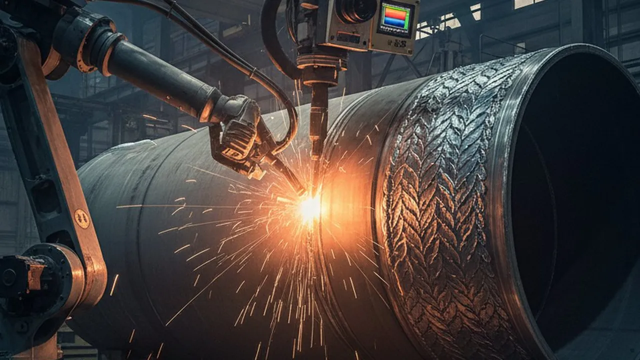
Laser welding is fast, narrow and mostly invisible from the outside. The keyhole is a fraction of a millimetre wide, the interaction zone is bright enough to saturate an ordinary camera, and a seam can be finished before an operator would notice anything. That is why laser lines are monitored by sensors rather than by eye. The harder question is which sensor.
There are four families of sensing methods, and they are not interchangeable: each measures a different physical quantity and catches a different set of faults. This article explains what each method sees, what it misses, and when a line needs more than one. It is written for process and quality engineers choosing a method, not for a specific application. The battery-module case is covered in laser welding monitoring for EV battery manufacturing.
Key takeaways
- Start from the failure mode that matters for the part, then choose the method that measures it. Choosing the sensor first usually leaves the critical defect uncovered.
- Process emission sensors are fast and compact, but they give a signal, not an image. Their thresholds must be validated per joint.
- Cameras, coaxial or off-axis, show seam position and geometry. The laser optics and the brightness of the interaction zone constrain how they are mounted and exposed.
- A thermal camera reads the heat field and cooling behaviour on and behind the seam. It does not see inside the keyhole.
- Direct depth measurement is the method for penetration. Indirect signals only correlate with depth, and that correlation has to be proven on cut sections.
Start from the failure mode
Laser welds fail in a small number of ways: insufficient or excessive penetration, lack of fusion between the sheets, seam off the joint line, porosity and spatter, humping or undercut at high speed, and cracking on sensitive alloys. Some are visible on the surface, some are not. Some develop inside the keyhole in milliseconds, others show up in how the seam cools.
Write down the two or three failure modes that actually reject parts on your line, and check which of them are detectable on the surface after welding. That list decides the method more than any sensor datasheet does.
Method 1: process emission sensors
Photodiode-based sensors read light from the interaction zone: typically the plasma or plume emission, the thermal radiation from the melt, and the laser light reflected back from the workpiece. Each band responds to changes in the process, such as a gap, contamination, a focus shift or an unstable keyhole.
Strengths: high sampling rate, compact, often integrated into the welding head, and a continuous signal per seam that is easy to trend and alarm on.
Limits: the output is a signal, not a picture. A deviation says that something changed, not where on the seam or what the defect looks like. Thresholds are joint-specific: the signal for a good weld on one material stack is not the reference for another. The method is as good as the reference set it was taught.
Method 2: cameras, coaxial or off-axis
A coaxial camera looks through the laser optics, so it always sees the interaction zone in the same place in the frame. That makes it a good fit for seam position, keyhole opening and melt pool shape. An off-axis camera sits beside the head and can see the seam before and after the laser, which suits joint finding and a surface check of the finished seam.
Strengths: geometry and position you can see and measure, and images an engineer can review when a part is rejected.
Limits: the interaction zone is extremely bright, so exposure, filtering and illumination decide what is visible. The frame rate has to match the travel speed for the event you want to catch. How to size frame rate for weld analysis covers that calculation. A coaxial camera also depends on the optical path of the welding head, so it has to be planned with the head, not added later.
Method 3: thermal camera on the heat field
A thermal camera reads temperature rather than light intensity. On a laser line it sits off-axis and looks at the seam and the parent material around it: seam width and continuity on the surface, local heat build-up at seam starts, ends and thin sections, and how the seam cools. Those are the signals linked to lack of fusion between sheets, burn-through on thin material and inconsistent energy delivery along the seam.
Strengths: a radiometric picture of where the heat went, recorded as an image per seam, which fits a per-part record and a comparison against a good-weld reference.
Limits: it does not see inside the keyhole, and it measures after the laser has passed, not at the instant of the event. Emissivity of bright metals such as copper and aluminium affects absolute readings, so the method usually compares each seam with a validated reference rather than relying on an absolute temperature. The choice of infrared band matters too; see SWIR, MWIR and LWIR for welding thermography.
Method 4: direct keyhole depth measurement
Optical depth measurement, typically interferometric and aligned through the laser optics, measures the distance to the bottom of the keyhole during welding. It is the only method in this list that reads penetration depth directly instead of inferring it.
Strengths: a direct depth trace along the seam, the closest inline signal to a cut section.
Limits: it needs to be integrated with the welding head optics, it measures along a line rather than across the seam, and it says little about surface defects, seam position or cooling. It is a specialised sensor class for lines where penetration is the critical failure mode.
When to combine methods
| Critical failure mode | Primary method | Useful second method |
|---|---|---|
| Insufficient or excessive penetration | Keyhole depth measurement | Process emission as a fast trend |
| Seam off the joint line | Camera (coaxial or off-axis) | Thermal camera for seam position after welding |
| Lack of fusion between sheets, burn-through | Thermal camera | Process emission |
| Porosity, spatter, keyhole instability | Process emission | Coaxial camera |
| Heat build-up at starts, ends, thin sections | Thermal camera | – |
Two methods are worth combining when they cover different failure modes, not when they measure the same thing twice. Every added sensor also adds a reference set to maintain and a threshold to validate.
Validate before you trust it
Whatever the method, the thresholds come from the line, not from the datasheet. A pilot on the actual joint, with deliberately produced good and bad welds confirmed by cut sections or the inspection method the contract requires, sets the thresholds and measures false alarms and missed defects. Only then should an alarm stop a part.
Where Therness fits
Therness works on the thermal and visual side of this list. HeatCam IR-S is a compact thermal camera built for integration on robot heads and machine frames, and PoolDrop is a high-speed visual camera, up to 480 frames per second, with Class 1 laser-safe illumination. Both work with the HeatCore platform, where each seam can be recorded and compared against a reference built from good welds. Therness does not make process emission sensors or keyhole depth sensors. Where a line needs those, the question is how their signals and the thermal record end up in the same per-part record. The welding camera guide compares the camera options in more detail.
Pick the method from the failure mode
Therness can help list the failure modes that reject parts on your laser line and check which of them a thermal or visual record can cover in a pilot.
Discuss your laser lineTherness solution: Welding camera — Thermal and high-speed imaging that watches the arc, the pool and the cooling seam while the weld is made.
Frequently Asked Questions
What sensing methods are used to monitor laser welding?
Four families: photodiode-based process emission sensors reading light from the interaction zone, cameras looking through the laser optics (coaxial) or from the side, thermal cameras reading the heat field on and behind the seam, and optical depth measurement of the keyhole. Each reads a different physical quantity, so they answer different questions.
Can a single sensor cover every laser welding defect?
No. Emission sensors react fast to changes in the interaction zone but give a signal, not an image. A camera shows geometry and position. A thermal camera shows how heat spread and how the seam cooled. Depth measurement shows penetration directly. Which one is enough depends on which failure mode matters most for the part.
When does penetration depth have to be measured directly?
When lack of penetration or over-penetration is the critical failure mode and it cannot be inferred reliably from surface signals, for example on joints where the underside is not accessible for inspection. Indirect methods can correlate with depth, but that correlation has to be validated on cut sections for the specific joint.
What does a thermal camera add on a laser welding line?
A read of the heat field around and behind the seam: seam width and continuity on the surface, cooling behaviour, and local heat build-up at the start, end or on thin sections. It is placed off-axis, outside the laser optics, and it records after the fact rather than inside the keyhole.
How should a sensing method be validated before production?
On a pilot with deliberately produced good and bad welds for the joint in question, confirmed by cut sections or the inspection method the contract requires. The pilot sets the alarm thresholds and measures false alarms and missed defects before the method is trusted on the line.