Infrared wavelength bands are the first specification that decides whether a welding thermography system produces a number you can defend or a picture you can only admire. Emissivity handling, filtering, frame rate and how close the sensor can sit to the arc all follow from the band the detector works in. Choose it last and the rest of the installation spends its life compensating. This guide covers what the band changes, how each band behaves next to an arc, and how to prove the choice on your own parts.
Key takeaways
- The band sets how steeply detected signal rises with temperature. Short bands make that slope steep, which suppresses emissivity error.
- The arc dominates short wavelengths and contributes far less at long ones, so band choice is the primary defence against arc interference.
- Long wave suits preheat, interpass and cool down; short wave suits molten metal and fast transients.
- Metals are the hard case in every band: emissivity is low, varies with surface state, and changes again as the surface oxidises.
- A band choice not verified against a contact reference on your own material is an assumption, not a specification.
- One camera almost never covers the full welding temperature range. Splitting the job is normal engineering, not a compromise.
What the wavelength band actually changes
An infrared camera does not measure temperature. It measures radiance inside a band of wavelengths its optics, filter and detector jointly accept, then converts that radiance using an assumed emissivity and an assumed reflected background. The band decides how forgiving that conversion is.
Why short bands tolerate emissivity error
Spectral radiance rises with temperature far more steeply at short wavelengths than at long ones. If the emissivity assumption is wrong by a given fraction, the temperature error is therefore smaller in a short band, because a smaller temperature change accounts for the same signal change. That is why high temperature process pyrometry has always lived there. The steepness has a cost: a short band device saturates quickly as temperature climbs and loses signal quickly as it falls, so its usable range per calibration is narrower.
Where the bands sit
The common industrial divisions are near and short wave infrared (NIR and SWIR), from the edge of visible light to about 1.7 micrometres; mid wave infrared (MWIR), roughly 3 to 5 micrometres; and long wave infrared (LWIR), roughly 8 to 14 micrometres. The vocabulary is standardised — ISO 10878 defines the terminology used across infrared thermographic testing — which matters when a specification, a datasheet and an inspection report must mean the same thing by “spectral range”.
Detector technology follows the band. LWIR instruments are usually uncooled microbolometers responding over milliseconds; SWIR and MWIR instruments are usually cooled photon detectors responding over microseconds. That decides whether you see an arc start or only its aftermath.
How each band behaves next to a welding arc
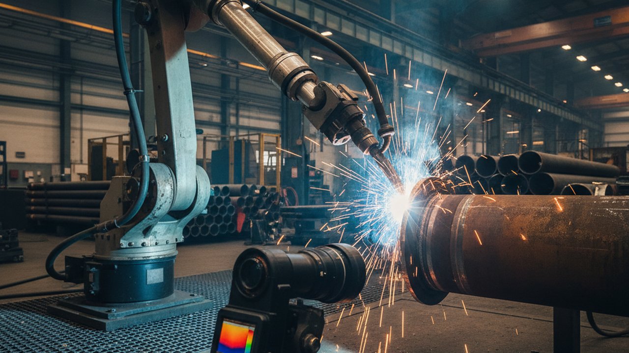
A welding arc is a plasma radiating intensely across the ultraviolet, visible and near infrared, with strong line emission from the shielding gas and the consumable. This is why a thermal camera and a process camera are not interchangeable instruments, and why band selection cannot be separated from arc management. The welding camera hub sets out the wider comparison before you narrow to a band.
Near infrared and short wave
SWIR sensors sit closest to the arc’s own emission, so they see it directly and saturate without aggressive filtering. Filtered to a narrow slice where the arc contributes little, a cooled short wave radiometer is the strongest option for a true molten-metal temperature: high signal, steep response, small emissivity penalty, and integration short enough to freeze droplet transfer. Below roughly 500 °C the signal collapses, which is why a device that images a weld pool beautifully reports nothing useful about the plate two minutes later. The visible-band route to the same droplet-transfer question is a high-speed weld pool camera with matched illumination, which answers pool geometry and stability without a radiometric band at all.
Mid wave
MWIR is the classic compromise for hot metal that is no longer molten: useful sensitivity down to a few hundred degrees while keeping part of the emissivity advantage of shorter wavelengths. Its complication is atmospheric. Water vapour and carbon dioxide absorb strongly in specific regions of this band, and the plume above a weld is rich in both, so instruments for this work are filtered to avoid those regions.
Long wave
LWIR is where most industrial thermography is done, and where preheat, interpass and cool down monitoring belong. Signal is available from below ambient upward, uncooled detectors keep cost and maintenance low, and fume scattering is weakest here, so the image survives imperfect extraction.
Its weakness mirrors SWIR’s strength: metal emissivity is low and variable, reflected radiation from hot surroundings is proportionally larger, and the shallow response slope turns an emissivity error into a larger temperature error. Long wave work on metals therefore lives or dies on emissivity handling for steel and aluminium.
A useful shorthand: short wave asks “how hot is this glowing metal, accurately”. Long wave asks “what is the thermal state of this assembly”. Most welding quality questions are the second kind, which is why long wave dominates production installations even though it is the harder band for absolute metal temperature.
Decision table: matching the band to the question
| Measurement question | Practical band | Why the band fits | Main watch-out |
|---|---|---|---|
| Preheat and interpass state of a fabrication | LWIR | Sensitive near ambient, uncooled, tolerant of fume | Emissivity and reflected background on bright steel |
| Heat affected zone extent and cooling behaviour | LWIR | Wide field, whole assembly in one frame | Needs a stable emissivity model across the scan |
| Molten pool geometry and stability | SWIR, narrow filter | High signal, freezes fast transients | Saturates without filtering, useless when cold |
| Droplet transfer and arc start events | SWIR, cooled detector | Microsecond integration | Very narrow usable temperature window |
| Hot metal above roughly 600 °C, arc off | MWIR or SWIR | Steep response reduces emissivity penalty | Gas absorption regions must be filtered out |
| Interlayer temperature on an additive build | LWIR | Target sits a few hundred degrees above ambient | Bead surface condition changes every layer |
| Post weld heat treatment soak | LWIR | Long dwell, moderate temperature, large area | Reflections inside enclosed furnaces and tents |
The table starts a specification; it does not replace the acceptance criteria in your own procedure. Where a temperature is recorded against a qualified range, the method is governed: ISO 13916 sets requirements for measuring preheating, interpass and preheat maintenance temperatures, and a camera-based method has to satisfy them rather than sidestep them.
Failure modes and fixes
The frame is white wherever the arc is visible
The detector is saturating on direct arc radiation. Filtering to a narrow band away from the arc’s strong emission is the real fix; cutting integration time alone trades saturation for an image too dark elsewhere. Shrouds, off-axis viewing and an aperture that excludes the arc column help, and are covered in the guide to arc glare and illumination in weld camera imaging.
Readings drift upward through a multi-pass weld with no real heat gain
Almost always oxidation. As the surface scales, emissivity rises, so the same true temperature yields more signal and the camera reports a climb. The fix is a fixed emissivity reference on the part, not a fixed number in the software.
Two cameras on one joint disagree by tens of degrees
Check the bands before the calibration. Two instruments in different bands applying the same emissivity value to the same low emissivity metal will legitimately disagree, because emissivity is a function of wavelength. That is evidence at least one emissivity model is wrong, not that a camera is faulty.
Numbers look right at the joint and impossible at the fixture
Reflected radiation. Polished clamps, jigs and torch bodies act as mirrors for the arc and the hot part. The compensation procedure for reflected apparent temperature appears in ISO 18434-1, which also covers emissivity and attenuating media, and is worth following formally rather than by eye.
Step by step: selecting and proving a band
- Write the measurement question first. Not “we want thermal monitoring” but “we need the interpass temperature of this joint, before each pass, to a stated uncertainty”.
- Fix the temperature window. State the coldest and hottest surface the instrument must report. A window spanning preheat and molten metal is a two instrument problem, and deciding that early is cheaper than discovering it at commissioning.
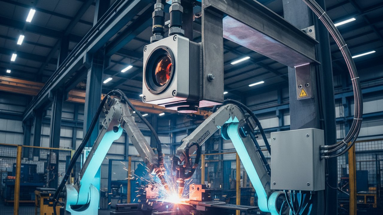
- Decide whether the arc is on during measurement. Arc-on forces narrow band filtering and usually a cooled short wave detector; arc-off opens the long wave option and cuts cost sharply.
- Characterise the surface and the optical path. Record the production surface condition, the standoff distance, the fume load and any protective window. A window transparent in one band can be effectively opaque in another.
- Match response speed to the event. Cooling curves lasting seconds suit an uncooled detector; events lasting milliseconds do not.
- Specify the instrument and its filter as one item, then run the paired trial below on your own material before the purchase order rather than after installation.
Selection checklist. Measurement question written down. Temperature window stated at both ends. Arc on or arc off decided. Production surface condition recorded. Path length and window material known. Required response time stated. Filter specified with the camera. Paired verification trial planned against a calibrated contact reference.
Where the question is heat input rather than temperature, the arithmetic side of the same problem is separate: the heat input calculator covers the parameter route while thermography covers the thermal result.
Verification: proving the choice on your own parts
A band choice is verified when the camera and an independent reference agree on your material, in your surface condition, over your temperature range, repeatably. It takes an afternoon.
The paired reading trial
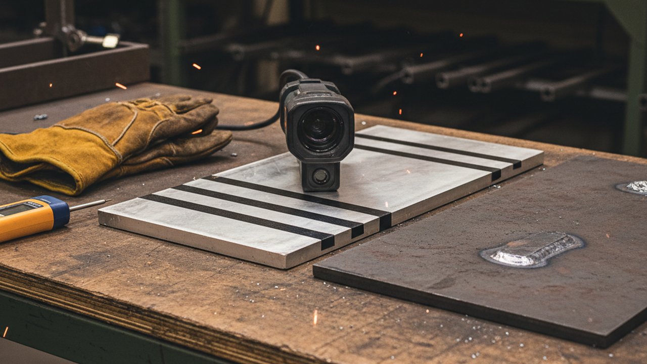
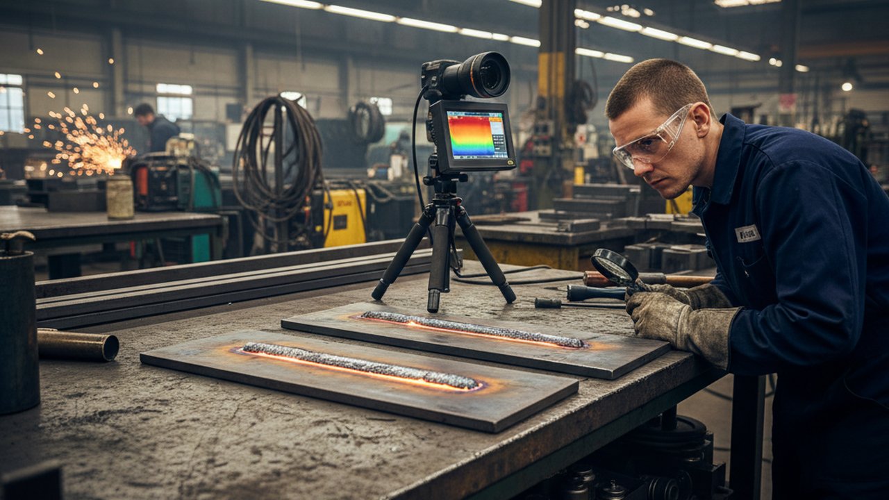
Prepare two coupons in the production surface condition, one per material. Heat one to the low end of the stated window and one toward the high end. Record the camera reading and, immediately after, a calibrated contact reading at the same marked spot. Repeat at least five times per coupon and keep every pair, including the ones that disagree.
A systematic offset that scales with temperature points at emissivity. Random scatter points at the optical path, the spot size or the operator. An offset appearing only on the bright coupon points at reflected background. None of this is visible from a single measurement, which is why single-point demonstrations prove little.
What to document
Record the band and filter fitted, the emissivity value and its justification, the reflected background value, the distance and any window in the path, the reference instrument and its calibration status, and the raw pairs — the evidence structure used across thermographic non-destructive testing work. Competence sits alongside the equipment: the schemes run by ASNT and BINDT exist because an infrared reading is an interpretation. Repeat the trial when the material or surface preparation changes, when the window is replaced, when the camera is moved, and on a fixed interval regardless.
Where band choice meets the standards
No welding code specifies a wavelength band, and none should. Codes state what must be controlled and recorded and leave the instrument to the fabricator, so a thermography installation has to satisfy the same method and competence requirements a contact thermometer does. Reference points when writing that part of a procedure: AWS and ASME for the qualification framework; CEN and CENELEC for European product standards; applied guidance from TWI and the International Institute of Welding; the radiation thermometry work at NIST a calibration certificate traces back to; and the literature indexed at NDT.net.
Two Therness instruments show the split. HeatCam IR-C is the cylindrical long wave device for cell-mounted interpass monitoring; HeatCam IR-S is the compact variant for embedded and additive installations. Neither is a high-speed droplet-transfer instrument: freezing transfer needs a cooled short wave detector, a different band and a different class of hardware. For interpass control, the interpass temperature monitoring guide covers the workflow once the band is settled.
FAQ
Why does the infrared band matter more than detector resolution in welding thermography? Resolution decides how small a feature you can resolve; the band decides whether the number attached to that feature means anything. A high resolution camera in the wrong band still reports a surface dominated by reflected arc light, and no amount of pixels recovers the true temperature.
Does a shorter infrared band reduce emissivity error on metals? Yes, for two reasons. Radiance rises far more steeply with temperature at short wavelengths, so a given emissivity error moves the reported temperature less. Most metals also radiate more efficiently at short wavelengths, so the correction being applied is smaller to begin with.
Can one thermal camera cover both preheat and molten weld pool temperatures? Rarely with one band and one integration setting. Preheat sits a few hundred degrees above ambient and needs long wave sensitivity; a molten pool is more than a thousand degrees hotter and saturates that same setting. Production cells normally split the job across two devices or two calibrated ranges.
How does arc radiation reach the detector in each infrared band? The arc radiates intensely in the ultraviolet, visible and near infrared, so short band sensors see it directly and can saturate. Longer bands receive far less arc emission, but they still pick up arc energy that has bounced off fixtures, torch bodies and the part itself as reflected radiation.
Do welding fume and shielding gas change infrared readings differently by band? Fume particles scatter short wavelengths much more strongly than long ones, so a short band image loses contrast first when extraction is poor. Gas and vapour absorb in narrow spectral regions rather than uniformly, which is why serious instruments avoid those regions by filter design.
Can a band choice be validated without a laboratory blackbody source? Partly. A calibrated contact measurement on the same spot immediately after the arc is off gives a usable cross check against the camera, and repeating it on a second material exposes a band or emissivity problem quickly. A traceable source is what turns that check into a documented calibration.
Not sure which band your application needs?
Send us the joint, the material and the temperature you actually have to record. We will tell you whether a long wave instrument answers it, and say so plainly when it does not.
Discuss your measurement caseTherness solution: Welding camera — Thermal and high-speed imaging that watches the arc, the pool and the cooling seam while the weld is made.
Frequently Asked Questions
Why does the infrared band matter more than detector resolution in welding thermography?
Resolution decides how small a feature you can resolve; the band decides whether the number attached to that feature means anything. A high resolution camera in the wrong band still reports a surface dominated by reflected arc light, and no amount of pixels recovers the true temperature.
Does a shorter infrared band reduce emissivity error on metals?
Yes, for two reasons. Radiance rises far more steeply with temperature at short wavelengths, so a given emissivity error moves the reported temperature less. Most metals also radiate more efficiently at short wavelengths, so the correction being applied is smaller to begin with.
Can one thermal camera cover both preheat and molten weld pool temperatures?
Rarely with one band and one integration setting. Preheat sits a few hundred degrees above ambient and needs long wave sensitivity; a molten pool is more than a thousand degrees hotter and saturates that same setting. Production cells normally split the job across two devices or two calibrated ranges.
How does arc radiation reach the detector in each infrared band?
The arc radiates intensely in the ultraviolet, visible and near infrared, so short band sensors see it directly and can saturate. Longer bands receive far less arc emission, but they still pick up arc energy that has bounced off fixtures, torch bodies and the part itself as reflected radiation.
Do welding fume and shielding gas change infrared readings differently by band?
Fume particles scatter short wavelengths much more strongly than long ones, so a short band image loses contrast first when extraction is poor. Gas and vapour absorb in narrow spectral regions rather than uniformly, which is why serious instruments avoid those regions by filter design.
Can a band choice be validated without a laboratory blackbody source?
Partly. A calibrated contact measurement on the same spot immediately after the arc is off gives a usable cross check against the camera, and repeating it on a second material exposes a band or emissivity problem quickly. A traceable source is what turns that check into a documented calibration.