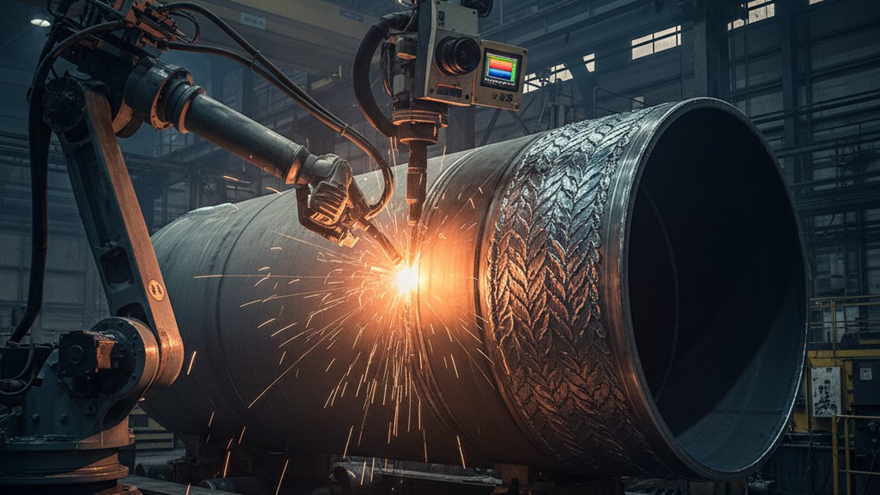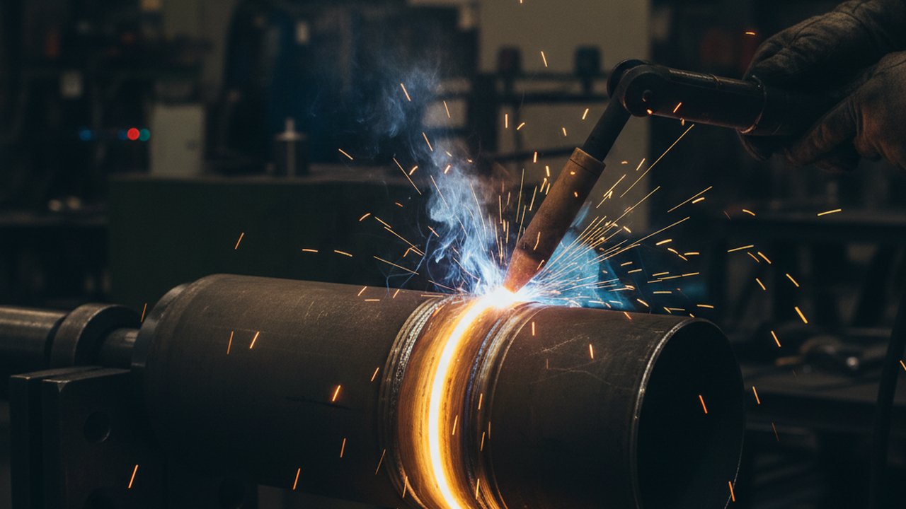
A circumferential weld does not heat the way a straight seam does. The torch travels a full 360° around a pipe, flange, or tubular joint and has to come back and fuse into the very metal it started on. By the time it gets there, the joint has changed: gravity pulls on the pool differently at each clock position, and the parent metal keeps absorbing arc heat the longer the revolution runs. That closing length — the tie-in — is where the geometry stacks the risk, because it is the one place on the joint where a cold start has to fuse into hot, already-welded metal instead of into cold parent material.
Thermal tracking around the joint turns that risk from a guess into a measurement: angular position feedback paired with a thermal reading shows whether the closing length actually reheated the way the rest of the circumference did, or came in cooler and shorter than it should have.
Key takeaways
- A circumferential weld’s start and its tie-in sit on thermally different parent metal, even though they are the same joint.
- The tie-in — where the closing pass fuses back into its own start — concentrates crater crack, lack-of-fusion, and overlap risk into a few centimetres.
- Gravity changes pool behaviour at different clock positions on the same revolution, and a tie-in landing overhead compounds two risks at once.
- Angular-position thermal tracking measures heat by sector, so the tie-in can be compared directly against the rest of the circumference instead of judged by eye.
- A cooler or shorter reheat at the tie-in is a precursor a monitoring system can flag before NDT, not proof of a defect on its own.
Why a circumferential weld heats unevenly around its own circumference
On a straight seam, the torch crosses each point once and moves on. A circumferential weld is a closed loop, and closing the loop changes the physics along the way.
The start lands on parent metal untouched by this pass — cold, or as cold as the preheat and interpass condition allow. As the arc keeps moving, the base metal keeps absorbing heat, so material further along the revolution is already warmer before the torch reaches it. By the time the arc completes the loop and arrives back at the tie-in, it is welding onto metal shaped by two heat histories at once: the residual heat of its own pass, and the crater left by the original start.
Gravity adds a second variable, but only in one of the two ways a circumferential weld gets made. When the torch orbits a fixed joint, the pool sees the flat, vertical, and overhead positions of a clock face in sequence, and it behaves differently at each. When the joint itself rotates under a fixed torch instead, the torch stays at one clock position and the pool stays flat for the whole revolution — that is the reason roll welding is chosen, and it removes the gravity variable without removing the heat-accumulation one. A tie-in on an orbiting-torch joint has no choice about which clock position it falls on; wherever the revolution closes is where the highest-risk metallurgy meets whatever gravity is doing at that point.
The tie-in: where the loop closes on itself
The tie-in is not a generic “end of the weld.” It is a short length where the bead does two things a straight seam never asks of one point: remelt the crater the pass started from, and carry enough heat into that crater to fuse it, not just lay fresh filler alongside it. Cut the overlap too short, or extinguish the arc too abruptly, and the closing length behaves like an arc stopped mid-pass — because for that stretch, it effectively is one.
ISO 6520-1 classifies three of the tie-in’s characteristic failure modes without needing a special category for “closure”: 104 — crater crack, 401 — lack of fusion, and 506 — overlap. Acceptance limits for each sit in ISO 5817, indexed by the same reference numbers — this article states that the rule exists, not what the numbers are.
Crater crack is the tightest fit: it forms when an arc is extinguished without the crater filled or tapered out, and the concave, thin-walled shape of an unfilled crater concentrates solidification shrinkage exactly there. A tie-in is, by definition, a crater the arc has to stop in — whether it fills it properly is the whole question the closing length has to answer.
What thermal tracking around the joint actually shows

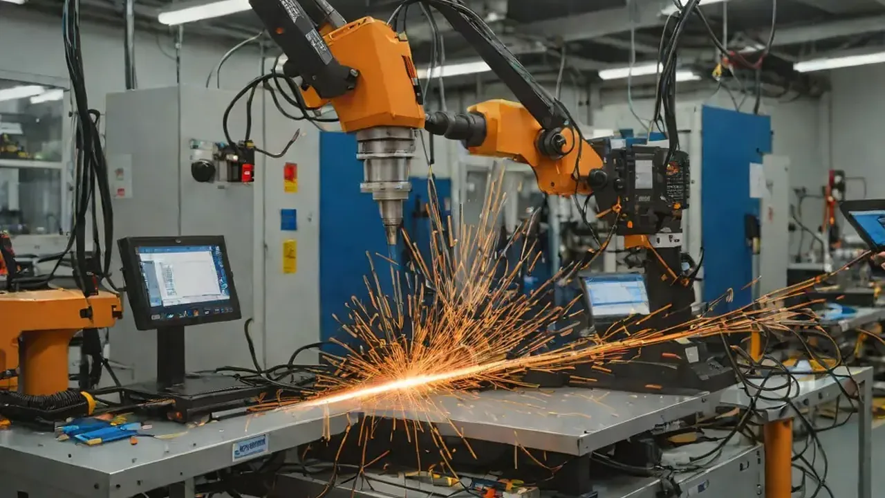
The clip above is the Tracking panel of HeatCore AI on one lab weld: frame by frame it reads the seam angle, the seam width and the offset of the seam from a reference line in millimetres, and plots that offset against an accepted range. It is a straight seam, not a circumferential joint — what carries over is the method. Read every frame of a circumferential pass against its position around the joint instead of a stopwatch, and the closing length can be judged against what every other sector of the same joint actually did. A tie-in that reheats to the same peak temperature and holds it for a comparable interval has done the metallurgical work a proper closure needs; one that reads cooler, or holds it for a shorter interval, has not — regardless of how the bead looks once the arc goes out.
| Where on the revolution | What changes | What a thermal record should show |
|---|---|---|
| Start | Cold parent metal, first heat of the pass | A clean initial ramp with no prior thermal history to compare against |
| Mid-revolution, flat/vertical sectors | Base metal already warmed by the pass so far | A gradually rising baseline temperature between passes, not a sign of a problem on its own |
| Overhead sector (fixed-joint / orbital setups) | Gravity works against pool support | Pool geometry and cooling uniformity worth checking against the joint’s other sectors |
| Tie-in / closure | Cold-start crater meets a hot, nearly-finished loop | A reheat that matches the peak temperature and dwell seen elsewhere on the same joint |
Reading by clock position rather than by time is the point of angular tracking: two joints welded at different speeds still line up sector by sector, which a plain time-based trace cannot do once revolution speed changes between parts or diameters.
Reading the tie-in on thermal data: the signals that matter
A monitoring system does not need to see a crack — it needs the signatures that correlate with one forming:
- A shorter reheat than the rest of the circumference. If peak temperature or dwell time at the closing length is measurably below the pattern the rest of the joint set, the arc likely left the crater before it was properly remelted.
- A cooling curve that does not match its neighbours. The tie-in sits between two sectors of the same weld; its cooling behaviour should resemble theirs. A curve that drops faster or slower is the same signature t8/5 cooling-rate measurement uses on straight seams, applied to the sector where the joint is most likely to fail.
- Interpass condition outside range at the moment the closing pass starts. A joint that has run hot for most of its revolution can put the tie-in above the qualified interpass temperature even though the pass started well within range — the interpass temperature timer tracks this the same way on a straight multi-pass joint.
None of these is a verdict alone. Together, flagged on the sector that matters, they turn “the tie-in looked fine” into a checkable claim.
Failure modes and fixes
- The tie-in is judged only by how the surface looks once the arc is out. By the time a crater is visible, the crack it may have started is buried. Fix: compare the closing length’s thermal signature against the rest of the circumference while the joint is still in the fixture.
- Thermal tracking runs against elapsed time, not angular position. A time-based trace cannot line two joints up sector by sector once travel speed or diameter changes. Fix: index the thermal record by position around the joint, not only by time.
- The overlap length is set once and never verified. A WPS-qualified overlap distance says nothing about whether it actually achieved fusion on this joint. Fix: use the thermal record, not the programmed distance, to confirm it.
- Interpass condition is tracked as one number for the whole pass. A joint that runs hot can exceed the qualified maximum at its own tie-in even while the pass average looks fine. Fix: check interpass condition specifically at the tie-in.
- Gravity-position risk and closure risk are tracked separately, if at all. A tie-in that falls in an overhead sector carries both risks at once. Fix: flag the clock position alongside the thermal reading, not the temperature alone.
Step-by-step: setting up angular thermal tracking on a circumferential weld cell
- Confirm the camera can resolve rotation into degrees, not just seconds. A trace that samples time evenly but rotation unevenly will misplace the tie-in.
- Mark the intended tie-in location on the WPS or fixture setup, so the system knows which sector gets the closure comparison, not the mid-revolution baseline.
- Capture a full baseline revolution on a joint you trust is sound, recording peak temperature and dwell by sector — a suspect tie-in gets compared against this, not a generic default.
- Log interpass condition at the moment the closing pass begins, not only as a running average for the whole weld.
- Set the alert threshold from the gap between a known-good tie-in and its own circumference, not an absolute temperature, and route the flag to where it is still actionable — before the part is unclamped.
Standards that classify and govern acceptance
ISO 6520-1 — classification
ISO 6520-1 gives crater crack, lack of fusion, and overlap their own reference numbers, in its groups for cracks, fusion imperfections, and shape imperfections — the same three categories a tie-in concentrates. The ISO 6520-1 reference card covers its scope and groups.
ISO 5817 — acceptance levels
ISO 5817 sets quality levels for fusion-welded joints in steel, nickel, titanium and their alloys, indexed by the ISO 6520-1 reference numbers above — this article does not restate what those levels require, that belongs in the standard and the governing WPS. The ISO 5817 reference card covers where it applies.
API 1104 — pipeline welding
API 1104 governs welding of pipelines in oil and gas service, including the circumferential girth welds this article’s geometry applies to. Its own tie-in term, for joining separately laid pipe strings, is distinct from the within-pass closure discussed above — the API 1104 acceptance criteria guide covers that standard’s structure in full.
Beyond the standards: TWI Job Knowledge, the International Institute of Welding, and the NDT Resource Center for inspection.
From watching the revolution to catching the tie-in live
Reviewing a full-revolution thermal trace after the fact tells you what the joint did. Catching a short reheat at the tie-in while the fixture still holds the part is what an in-process system is for: HeatCam IR-C is the fixed-mount thermal camera for that view of the joint, and HeatCore AI records the thermal image and the seam reading frame by frame, against time or position along the weld, so the closing length can be compared with the rest of its own joint, not with a generic threshold. A welding monitoring system built around that comparison flags a short tie-in reheat before the part reaches NDT.
For the cooling-rate side of the same joint away from the tie-in, see orbital tube welding cooling rate monitoring and why measure t8/5 cooling time on every production weld. For the seam-tracking clip shown above, with what it reads frame by frame, see HeatCore AI — seam tracking on a replayed lab weld.
FAQ
What is the tie-in on a circumferential weld? The tie-in is the short overlap where a circumferential weld pass closes the loop and fuses back into its own starting point. The torch travels a full revolution and the closing length of the bead has to remelt the crater it started from, not just lay new metal next to it.
Why does a circumferential weld heat unevenly around its own circumference? Because the joint is not a straight line the torch crosses once. The start of the revolution sits on parent metal at or near ambient temperature, while the closing length arrives on a joint that has been soaking up arc heat for the whole trip around, so the two ends of the same pass are welded onto thermally different material.
What defect is most associated with the tie-in of a circumferential weld? Crater crack, ISO 6520-1 reference 104, forms specifically where an arc is extinguished without the crater being filled or tapered out, which is exactly the geometry at a tie-in. Lack of fusion and overlap at the restart are the other two failure modes concentrated at the same few centimetres.
How much overlap should the closing pass of a circumferential weld have? That is a procedure-specific number set by the qualified WPS for the joint, thickness, and process in front of you, not a fixed figure. What a monitoring system can verify independently of that number is whether the actual overlap achieved fusion, by comparing the thermal signature of the closing length against the rest of the circumference.
Can thermal imaging catch a tie-in defect before the weld is finished? It can catch the precursor condition, not the crack itself. A thermal camera tracking angular position sees whether the closing length reached the peak temperature and dwell time the rest of the pass reached; a cooler or shorter-than-expected reheat at the tie-in is the signal to flag before the part goes to NDT, not proof a crack exists.
Does gravity change where defects form around a circumferential weld? Yes, but only when the torch orbits a fixed pipe or vessel. In that setup the weld pool sees the overhead, vertical, and flat positions of the same revolution because gravity pulls on it differently at each. On a rotated joint welded under a fixed torch, the torch stays at one clock position and the pool stays flat for the whole revolution, so gravity is not the variable there — heat accumulation still is. A tie-in landing in an overhead sector on an orbiting-torch joint compounds two separate risks in the same few centimetres.
Is a circumferential weld tie-in the same thing as a pipeline tie-in weld? No, though the two share a name because both describe a joint that connects something back to itself or to another piece under restraint. A pipeline tie-in weld joins two separately laid pipe strings; the tie-in discussed here is the closing overlap within one circumferential pass on a single joint, which is what this article covers.
What frame rate does angular-position thermal tracking need on a circumferential weld? It needs to resolve degrees of rotation, not just elapsed time, so the required rate scales with revolution speed: a fast-rotating small-diameter pipe needs more frames per degree than a slow orbital head on a large vessel. The practical test is whether consecutive frames show a smooth angular progression around the joint rather than gaps between sampled sectors.
See the tie-in before it becomes a crack
In a pilot, Therness records the closing length of the weld frame by frame next to the rest of the same joint, so it is compared with its own weld, not judged by eye after the arc goes out.
Talk to an engineerTherness solution: Welding parameter monitoring — Current, voltage, wire feed and gas recorded per weld, as WPS/PQR and heat-input evidence.
Frequently Asked Questions
What is the tie-in on a circumferential weld?
The tie-in is the short overlap where a circumferential weld pass closes the loop and fuses back into its own starting point. The torch travels a full revolution and the closing length of the bead has to remelt the crater it started from, not just lay new metal next to it.
Why does a circumferential weld heat unevenly around its own circumference?
Because the joint is not a straight line the torch crosses once. The start of the revolution sits on parent metal at or near ambient temperature, while the closing length arrives on a joint that has been soaking up arc heat for the whole trip around, so the two ends of the same pass are welded onto thermally different material.
What defect is most associated with the tie-in of a circumferential weld?
Crater crack, ISO 6520-1 reference 104, forms specifically where an arc is extinguished without the crater being filled or tapered out, which is exactly the geometry at a tie-in. Lack of fusion and overlap at the restart are the other two failure modes concentrated at the same few centimetres.
How much overlap should the closing pass of a circumferential weld have?
That is a procedure-specific number set by the qualified WPS for the joint, thickness, and process in front of you, not a fixed figure. What a monitoring system can verify independently of that number is whether the actual overlap achieved fusion, by comparing the thermal signature of the closing length against the rest of the circumference.
Can thermal imaging catch a tie-in defect before the weld is finished?
It can catch the precursor condition, not the crack itself. A thermal camera tracking angular position sees whether the closing length reached the peak temperature and dwell time the rest of the pass reached; a cooler or shorter-than-expected reheat at the tie-in is the signal to flag before the part goes to NDT, not proof a crack exists.
Does gravity change where defects form around a circumferential weld?
Yes, but only when the torch orbits a fixed pipe or vessel. In that setup the weld pool sees the overhead, vertical, and flat positions of the same revolution because gravity pulls on it differently at each. On a rotated joint welded under a fixed torch, the torch stays at one clock position and the pool stays flat for the whole revolution, so gravity is not the variable there — heat accumulation still is. A tie-in landing in an overhead sector on an orbiting-torch joint compounds two separate risks in the same few centimetres.
Is a circumferential weld tie-in the same thing as a pipeline tie-in weld?
No, though the two share a name because both describe a joint that connects something back to itself or to another piece under restraint. A pipeline tie-in weld joins two separately laid pipe strings; the tie-in discussed here is the closing overlap within one circumferential pass on a single joint, which is what this article covers.
What frame rate does angular-position thermal tracking need on a circumferential weld?
It needs to resolve degrees of rotation, not just elapsed time, so the required rate scales with revolution speed: a fast-rotating small-diameter pipe needs more frames per degree than a slow orbital head on a large vessel. The practical test is whether consecutive frames show a smooth angular progression around the joint rather than gaps between sampled sectors.