Weld splatter remains one of the most visible and costly quality issues in both manual and robotic welding operations. Those tiny molten metal droplets that eject from the weld pool don’t just create extra cleanup work—they signal underlying process instabilities that can lead to lack of fusion, porosity, and costly rework. What if you could detect splatter formation as it happens and correct welding parameters before a single droplet escapes?
Why Splatter Detection Matters Beyond Cleanup
Traditional approaches treat weld splatter as a post-process nuisance—grinding it off, blaming operator technique, or accepting it as “part of the process.” This mindset misses the critical insight: splatter is a leading indicator of weld pool instability.
When splatter increases, it often precedes:
- Lack of fusion due to excessive heat input variation
- Porosity from disrupted gas shielding
- Undercut from arc wandering
- Inconsistent bead geometry affecting fatigue strength
Each splatter event represents wasted energy, consumed filler metal, and potential defect initiation sites. In automotive manufacturing, where a single welded body-in-white contains 5,000+ welds, even a 1% increase in splatter-related rework can add hundreds of dollars per vehicle in avoidable costs.
How Thermal Imaging Detects Splatter Formation
Thermal cameras don’t just see hot spots—they capture the dynamic temperature evolution of the weld pool with microsecond resolution. This enables splatter detection through three complementary mechanisms:
1. Precursors in Weld Pool Oscillation
Before splatter detaches, the weld pool exhibits characteristic oscillation patterns. Thermal cameras operating at 100-1000 fps capture these surface tension-driven oscillations. Changes in oscillation frequency and amplitude correlate directly with impending splatter events.
2. Thermal Signature of Ligament Formation
As splatter prepares to detach, a thin molten ligament forms between the droplet and the weld pool. This ligament creates a distinct thermal fingerprint—a rapidly cooling, high-surface-area-to-volume structure that appears as a fast-decaying hot spot in thermal imagery.
3. Post-Detachment Cooling Trajectory
Once detached, splatter droplets follow predictable cooling curves based on their size, initial temperature, and ambient conditions (watch high-speed weld-pool droplet transfer frame by frame). Tracking these trajectories confirms splatter events and enables measurement of droplet size distribution—a key parameter for predicting downstream defects.
Real-Time Feedback Loop: From Detection to Correction
Detection alone has limited value. The power comes from connecting thermal splatter detection to immediate welding parameter adjustments through Therness’s real-time weld monitoring platform:
Thermal Camera → Real-time Splatter Detection Algorithm → Process Deviation Alert → Automatic Parameter Adjustment Suggestion → Welder/Robot Controller → Corrected Welding Parameters → Reduced Splatter in Next Weld Cycle
This closed-loop system typically responds within 100-200 milliseconds—fast enough to influence the current weld or the very next one in a robotic sequence.
Case Study: Automotive Tier Supplier Results
A Tier 1 automotive supplier manufacturing electric vehicle battery trays implemented Therness thermal monitoring focused on splatter reduction:
Baseline:
- Average splatter events: 8.2 per meter of weld
- Post-weld grinding time: 4.2 minutes per part
- Visual rework rate: 12% (splatter-related)
After 90 Days of Thermal Monitoring:
- Splatter events reduced to 3.1 per meter (-62%)
- Grinding time reduced to 1.8 minutes per part (-57%)
- Visual rework rate dropped to 4% (-67%)
- Estimated annual savings: €240,000 across 3 robotic cells
The system didn’t just detect splatter—it identified that splatter spikes correlated with minor fluctuations in wire feed speed (±2.5%) that were invisible to traditional electrical monitoring. Correcting these micro-variations eliminated the root cause.
Integration with Existing Welding Systems
Integration of the full Therness monitoring lineup is scoped against the cell you already run. Check these points before a pilot:
Integration Checks:
- Robotic welding cell: which alarm or stop signal the robot controller can accept from the monitoring system, and where it acts in the cycle
- Welding power source: which process signals (current, voltage, wire feed speed) are available to correlate with the thermal data
- Communication: Ethernet/IP, Profibus, Profinet, Modbus TCP, discrete I/O
Data Outputs:
- Real-time splatter event counters (configurable sensitivity)
- Splatter size distribution metrics
- Weld pool stability indices
- Alarm outputs for immediate operator notification
- Historical trend analysis for process optimization
Beyond Splatter: Comprehensive Weld Pool Monitoring
While splatter detection delivers immediate ROI, the same HeatCore AI defect-scoring engine provides additional quality assurance capabilities:
Early Defect Prediction
- Lack of fusion detection through abnormal pool temperature gradients
- Porosity warning from rapid cooling events disrupting gas entrapment
- Undercut prediction from excessive weld pool oscillations near plate edges
Process Optimization
- Heat input control via actual weld pool temperature measurements
- Travel speed verification through pool length tracking
- Wire stickout monitoring from pre-heat patterns ahead of the arc
Documentation & Traceability
- Automatic generation of ISO 17635-compliant thermal records
- Correlation of splatter events with welding parameter logs
- Digital twins of thermal behavior for each weld joint specification
Implementation Strategy for Maximum Impact
To achieve the fastest return on your thermal monitoring investment:
Phase 1: Baseline Assessment (Week 1)
- Map current splatter-related costs (grinding labor, rework, consumables)
- Identify highest-volume, highest-splatter weld joints
- Establish baseline splatter frequency using existing vision systems or manual observation
Phase 2: Shadow Mode Validation (Weeks 2-3)
- Run thermal monitoring in parallel with current processes
- Correlate thermal splatter alerts with actual splatter observations
- Fine-tune detection sensitivity for your specific welding process and materials
Phase 3: Closed-Loop Activation (Week 4)
- Enable automatic parameter adjustment suggestions
- Train operators and supervisors on interpreting thermal feedback
- Begin tracking reduction in splatter-related rework
Phase 4: Scale & Optimize (Ongoing)
- Expand to additional weld joints and robotic cells
- Use splatter reduction data to negotiate decreased NDT sampling rates
- Implement predictive maintenance based on thermal drift analysis
Frequently Asked Questions
Q: Can thermal cameras distinguish splatter from other hot objects like sparks or debris?
A: Yes. Splatter detection algorithms analyze not just temperature but also size, shape, trajectory, and temporal behavior—distinguishing true weld splatter from environmental false positives with >95% accuracy.
Q: What’s the minimum detectable splatter size?
A: With proper lens selection and camera placement, systems can detect splatter formation as small as 0.2mm diameter—well before it becomes visible to the naked eye or standard vision systems.
Q: Does this require changing our welding parameters or procedures?
A: No. The system works within your existing welding window, providing feedback to optimize within those parameters. Procedure changes only occur if you choose to expand your operating window based on improved process understanding.
Q: How does this compare to acoustic or vision-based splatter detection?
A: Thermal detection offers advantages in harsh environments (immune to ambient light, less sensitive to acoustic noise), provides direct temperature metrics for process understanding, and detects splatter formation earlier than vision systems that require complete droplet detachment.
Taking the Next Step
Weld splatter isn’t inevitable—it’s a solvable process control problem. Manufacturers using real-time thermal monitoring typically see:
- 30-50% reduction in splatter-related grinding and rework
- Improved first-pass yield in downstream machining and painting
- Extended consumable life (contact tips, nozzles) from more stable arcs
- Data-driven justification for reduced NDT sampling based on demonstrated process stability
Ready to see how thermal splatter detection works in your specific welding application? Book a demo to discuss your splatter challenges and see sample data from similar materials and processes.
Therness helps manufacturers achieve zero-defect welding through real-time thermal monitoring, intelligent quality software, and agentic workflows that turn thermal data into immediate process improvements.
See spatter flagged live on your line
Real-time thermal monitoring detects splatter as it forms and feeds parameter corrections back within milliseconds — cutting grinding and rework 30–50%. Book a demo to see sample data from a process like yours.
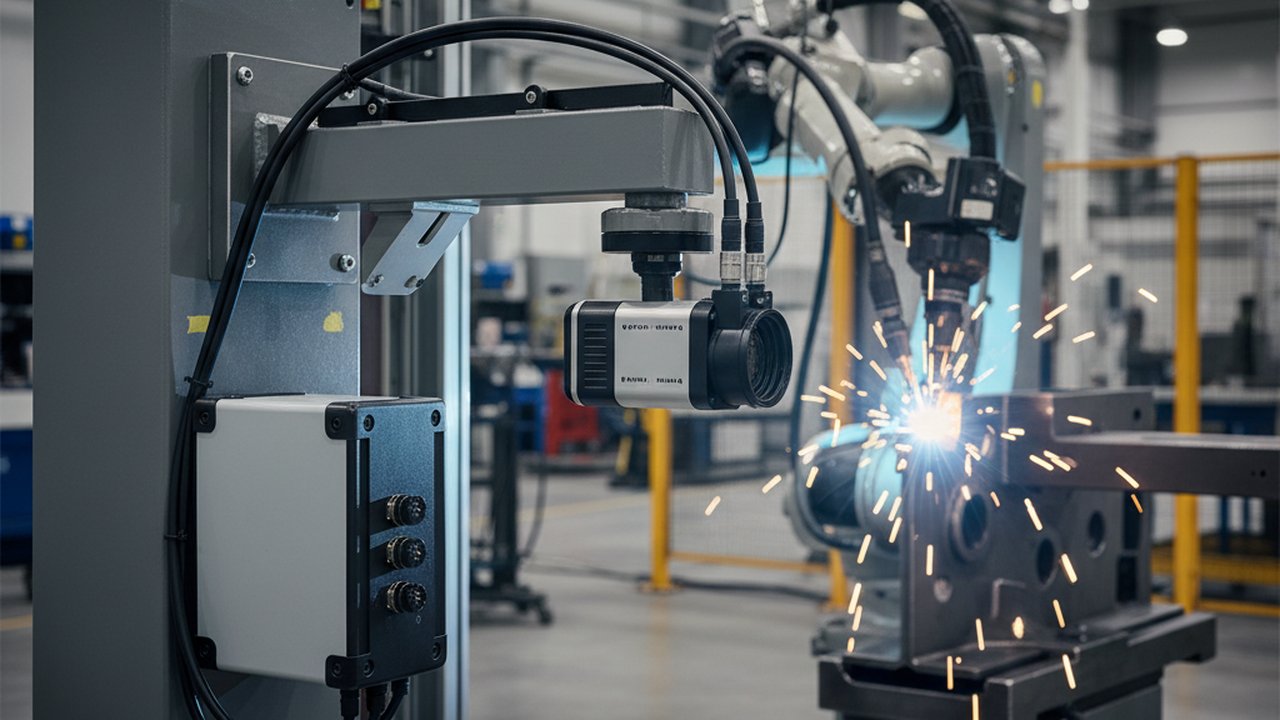
Book a demo See the real-time weld monitoring platformTherness solution: Welding camera — Thermal and high-speed imaging that watches the arc, the pool and the cooling seam while the weld is made.