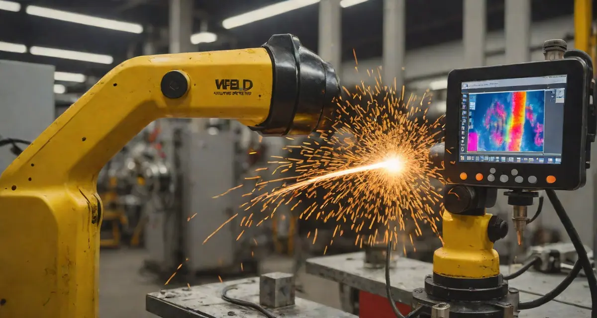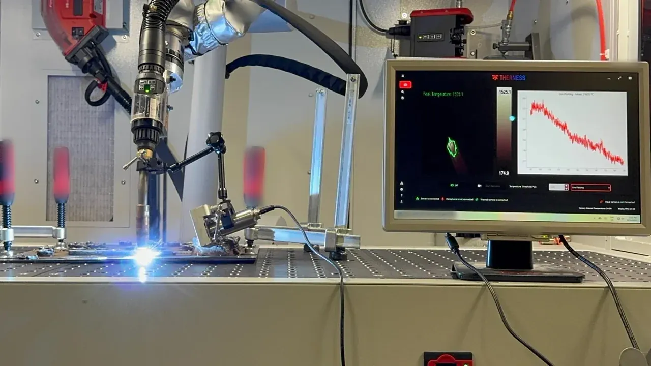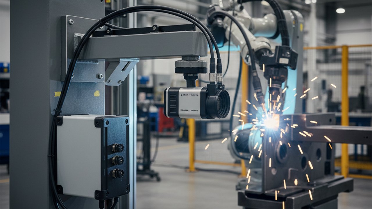
Inline thermal inspection setup is where most weld-monitoring programs are won or lost — not in the choice of camera, but in where it points, when it captures, and how its readings tie back to a control limit that means something. A thermal sensor bolted onto a welding station without a deliberate field of view, trigger logic, and calibration plan produces a data stream nobody trusts, which is functionally the same as having no sensor at all. Getting the setup right the first time is cheaper than fixing it after a quality audit asks where the evidence came from.
This guide walks through the mechanics of putting a thermal camera to work on a live welding line: physical placement, the trigger signals that define what gets recorded, the calibration discipline that keeps readings meaningful over time, and the verification loop that proves the setup still works six months after commissioning.
Key takeaways
- Camera placement has to hold the weld pool and trailing heat-affected zone in frame across the joint’s full range of motion, not just at a single fixed point.
- Trigger logic — usually a PLC or robot arc-on/arc-off signal — determines whether the system captures the actual weld or a mix of weld and idle frames.
- Emissivity and reference-target calibration drift over time; a setup verified only once at commissioning will silently lose accuracy.
- Inline thermal inspection screens the process in real time; it is not a substitute for volumetric NDT methods that confirm subsurface defects.
- A setup that is not wired into the same SPC control limits and PFMEA detection scoring as the rest of the quality system operates as an isolated add-on, not evidence.
- Pilot on one station before rolling the setup out across a line, and re-verify after any lens, mounting, or filter change.
Table of Contents
- What Inline Thermal Inspection Setup Actually Involves
- Planning Camera Placement, Field of View, and Trigger Points
- Step-by-Step: Commissioning an Inline Thermal Inspection Setup
- Common Setup Failure Modes — and How to Fix Them
- Validating and Verifying the Setup After Go-Live
- Connecting Inline Thermal Inspection to SPC, PFMEA, and Standards
- Frequently Asked Questions
Most inline thermal inspection failures are not sensor failures — they are setup failures: a field of view that loses the pool mid-weld, a trigger that captures idle frames, or a calibration that was never repeated after commissioning.
What Inline Thermal Inspection Setup Actually Involves
Inline thermal inspection setup covers everything that turns a thermal camera into a working monitoring point on a welding line: mechanical mounting, optical alignment, the electrical or software trigger that defines the capture window, emissivity and reference calibration, and the data path that carries readings into a threshold or alarm system. It is distinct from selecting a camera — two identical cameras can produce completely different quality outcomes depending entirely on how the setup around them was done.
The setup sits inside a broader live weld camera and thermal monitoring architecture, but it deserves its own attention because it is where a program most often stalls after the hardware has already been purchased and installed. A camera pointed slightly off-axis, or triggered on the wrong signal, still produces a live video feed that looks correct on a monitor — the failure is invisible until someone tries to use the data for a decision and finds it does not correspond to what actually happened at the arc.
Planning Camera Placement, Field of View, and Trigger Points
Placement starts with the joint geometry, not the camera. Map the full range of motion the weld pool travels through — a straight fillet weld has a simple, fixed path, while a robotic cell running multiple joint types on one fixture needs a field of view wide enough to hold the pool across every program, or a camera that repositions between programs. A field of view that only works for one joint type on a multi-product line is a setup that will silently stop capturing correctly the moment the line changes over.
| Placement factor | Typical range | Why it matters |
|---|---|---|
| Standoff distance from arc | 200-400mm | Closer risks lens fouling and heat damage; farther loses spatial resolution on small defects |
| Viewing angle off the weld axis | 15-45 degrees | Reduces direct arc glare and specular reflection while keeping the pool geometry readable |
| Field of view margin beyond joint travel | 15-20% | Compensates for fixture tolerance and part-to-part variation without losing the pool at the edges |
| Frame rate | 30-60 FPS for pool geometry, higher for spatter/transfer analysis | Matched to travel speed and the fastest event the setup needs to resolve |
Trigger logic determines what is actually in the recorded data, and it is the single most under-specified part of most inline setups. Two approaches dominate. The first ties capture to a PLC or robot digital I/O signal — arc-on opens the window, arc-off closes it — which is the most reliable option on automated or robotic cells because the signal already exists in the weld controller. The second, used on manual stations without a clean digital signal, triggers on current sensing or motion detection at the torch; it is less precise but avoids new wiring into an existing manual cell.
Some setups trigger on physical proximity alone — the camera records whenever something is in frame — which captures idle dwell time, tack welds, and fixture movement alongside the actual weld pass. That noise dilutes the dataset and makes threshold-setting far harder than it needs to be.
Step-by-Step: Commissioning an Inline Thermal Inspection Setup
- Map the joint geometry and travel path. Document every joint type and program the station runs, and identify the field of view that holds the pool across all of them.
- Select standoff, angle, and lens. Choose the mounting geometry from the table above, and confirm line-of-sight is not blocked by the torch, wire feeder, fume extraction, or fixturing at any point in the weld cycle.
- Wire the trigger signal. Connect to the existing arc-on/arc-off PLC or robot I/O where available; fall back to current or motion sensing only where no digital signal exists.
- Set emissivity and run reference-target calibration. Calibrate against a known-temperature reference appropriate to the base material and surface condition, not a generic factory default.
- Capture a baseline dataset on known-good welds. Run a representative sample of parts that have already passed final inspection, and record the thermal signature as the reference distribution.
- Set initial thresholds from the baseline, not from a vendor default. A limit copied from a different material, thickness, or joint type will either fire constantly or never fire.
- Pilot on one station for two to four weeks. Compare alerts against real dispositions before expanding the setup to additional stations or lines.
- Document the setup as a controlled record. Standoff distance, angle, emissivity setting, trigger source, and calibration date should be recorded and version-controlled, not left as tribal knowledge.
- Schedule the recalibration cadence. Fix a periodic interval — commonly quarterly — and assign an owner before the setup goes into full production use.
Common Setup Failure Modes — and How to Fix Them
| Setup failure | Why it happens | Fix |
|---|---|---|
| Pool drifts out of frame mid-weld | Field of view sized for one joint type only | Widen the field of view or add a repositioning routine for multi-product lines |
| Trigger captures idle and tack-weld frames | Proximity-based trigger instead of arc-on/arc-off signal | Wire the capture window to the weld controller’s digital I/O |
| Readings drift after a few weeks | Calibration checked only at commissioning | Add a fixed recalibration cadence with an assigned owner |
| Thresholds fire constantly or never | Limits copied from a different process or vendor default | Derive thresholds from a baseline dataset of known-good welds on this joint |
| Lens fouled by spatter or fume | Standoff distance too short for the process | Increase standoff, add a protective window, or schedule cleaning intervals |
| Setup details exist only as tribal knowledge | No commissioning record kept | Document standoff, angle, emissivity, trigger source, and calibration date as a controlled record |
Guidance on avoiding common infrared-imaging setup errors, including emissivity and reflection pitfalls, is covered in depth in the SPIE Thermosense conference proceedings, which remains one of the most consistent technical venues for infrared thermography practice across industrial applications.
Validating and Verifying the Setup After Go-Live
A setup is not verified because it was configured correctly once — it is verified because someone continues to check that it still behaves correctly. Three checks belong on a recurring schedule, not just at commissioning.
First, confirm the field of view still holds the pool after any fixture change, tooling swap, or robot program edit. A setup that was correct on day one can silently lose coverage after an unrelated change elsewhere on the cell.
Second, re-run the reference-target calibration on the cadence set during commissioning, and immediately after any lens, filter, or mounting change. Emissivity drift and small mechanical shifts are the most common source of a thermal setup that looks fine on screen but reads consistently high or low. Independent technical resources such as TWI’s technical knowledge base and published work in Infrared Physics & Technology are useful cross-checks when evaluating calibration methodology against current practice.
Third, cross-reference alerts against real dispositions and final inspection. Pull every threshold crossing over a defined period and confirm what fraction corresponded to an actual scrapped, reworked, or flagged part, and separately confirm that parts rejected downstream had a corresponding inline reading. A gap in either direction means the setup — not necessarily the camera — needs attention. Personnel performing thermographic testing as a qualified NDT method should hold certification consistent with ISO 9712, which is the reference most quality systems already use for other NDT personnel qualification.
Connecting Inline Thermal Inspection to SPC, PFMEA, and Standards
An inline thermal inspection setup that runs in isolation from the rest of the quality system produces a video feed, not evidence. The same baseline data used to set thresholds during commissioning should feed the control limits in SPC charts for welding, and the failure modes the setup is meant to catch should trace back to detection controls named in the process PFMEA — maintaining two disconnected definitions of “normal” for the same process is a common and avoidable source of conflicting signals.
On the standards side, ISO 3834-2 requires documented process control appropriate to its comprehensive quality level, and a commissioned, calibrated, and periodically re-verified inline thermal setup is one of the more concrete ways to demonstrate that requirement with evidence rather than a procedure that exists only on paper. ISO 17635 sets the general rules non-destructive testing methods for welded joints are expected to follow, which is useful context for where inline thermal screening fits alongside volumetric methods like radiographic and ultrasonic testing rather than replacing them — see this site’s guide to passive vs. active thermographic inspection and industrial applications of active thermography for how the two approaches divide the inspection workload. For broader codes-and-standards context, see ASME’s codes and standards program, NIST’s manufacturing resources on process control and Industry 4.0 data practices, and the American Welding Society’s guidance on weld defects for the failure modes an inline setup is typically configured to catch.
Recurring calibration and verification of the underlying camera and mounting is its own discipline, covered in more depth in this site’s guide to thermal monitoring calibration, verification, and validation. For teams standing up a first inline station, HeatCore Basic is built specifically for this entry point — thermal monitoring that mounts on a fixture or workstation without a cloud or IT dependency, with the SPC analytics needed to turn the setup work above into usable control limits from day one — and scales into the broader welding monitoring system as coverage expands across a line. Teams evaluating inline thermal inspection alongside other thermography and NDT testing methods, or wanting the resulting data connected directly into quality records, often pair the setup with AI-assisted QMS tooling so alert history, calibration records, and disposition data stay in one system instead of drifting apart across spreadsheets.
Frequently Asked Questions
What is inline thermal inspection?
Inline thermal inspection mounts a thermal (infrared) camera directly on or beside a welding station so it captures the weld pool or joint temperature signature as the weld is made, rather than inspecting a finished part afterward. The feed is processed in real time against thresholds tied to known defect signatures.
Where should a thermal camera be mounted for inline weld inspection?
Mount the camera so the weld pool and trailing heat-affected zone stay in frame across the full range of joint motion, typically 200-400mm from the arc at an angle that avoids direct arc glare while keeping the optical path unobstructed by the torch, wire feeder, or fixturing.
What triggers an inline thermal inspection reading?
Most setups use a PLC or robot digital I/O signal (arc-on, weld-start) to open the capture window and a corresponding arc-off signal to close it, so the system records only the active weld rather than idle frames. Some manual-station setups instead use a motion or current-sensing trigger.
How often does an inline thermal camera need calibration?
Emissivity and reference-target calibration should be checked at commissioning, after any lens, filter, or mounting change, and on a fixed periodic cadence, commonly quarterly, consistent with the verification interval used for other inline monitoring equipment on the line.
Does inline thermal inspection replace post-weld NDT?
No. Inline thermal inspection screens for process excursions and surface-visible thermal anomalies in real time; it does not replace volumetric NDT methods such as radiographic or ultrasonic testing for defects like subsurface porosity or lack of fusion that require a different inspection method to confirm.
What standards apply to inline thermal weld inspection?
ISO 3834-2 requires documented process control appropriate to its comprehensive quality level, which inline monitoring evidence supports. ISO 17635 sets general rules for non-destructive testing of welded joints, and personnel qualification for thermographic testing as an NDT method follows ISO 9712.
What is the difference between passive and active thermal inspection on a weld line?
Passive inline inspection reads the heat already generated by the welding process itself, such as the pool and cooling signature. Active thermography instead applies an external heat stimulus to the finished joint to reveal subsurface features, and is typically run as a separate post-weld station rather than inline during welding.
Why do inline thermal inspection setups fail after go-live?
The most common causes are thresholds copied from a different process without local process-capability data, camera drift from mounting vibration or thermal cycling that was never re-verified, and alert data that stays isolated from SPC and PFMEA records instead of feeding the same quality system.
Setting up inline thermal inspection on a welding line?
We help welding and quality teams plan camera placement, trigger logic, and calibration for inline thermal inspection tied to SPC and PFMEA evidence.
Book a setup consultationTherness solution: Welding monitoring system — Every weld inspected in the cycle, with defect flags and the ISO 3834 / ISO 17635 evidence kept per weld.
Frequently Asked Questions
What is inline thermal inspection?
Inline thermal inspection mounts a thermal (infrared) camera directly on or beside a welding station so it captures the weld pool or joint temperature signature as the weld is made, rather than inspecting a finished part afterward. The feed is processed in real time against thresholds tied to known defect signatures.
Where should a thermal camera be mounted for inline weld inspection?
Mount the camera so the weld pool and trailing heat-affected zone stay in frame across the full range of joint motion, typically 200-400mm from the arc at an angle that avoids direct arc glare while keeping the optical path unobstructed by the torch, wire feeder, or fixturing.
What triggers an inline thermal inspection reading?
Most setups use a PLC or robot digital I/O signal (arc-on, weld-start) to open the capture window and a corresponding arc-off signal to close it, so the system records only the active weld rather than idle frames. Some manual-station setups instead use a motion or current-sensing trigger.
How often does an inline thermal camera need calibration?
Emissivity and reference-target calibration should be checked at commissioning, after any lens, filter, or mounting change, and on a fixed periodic cadence, commonly quarterly, consistent with the verification interval used for other inline monitoring equipment on the line.
Does inline thermal inspection replace post-weld NDT?
No. Inline thermal inspection screens for process excursions and surface-visible thermal anomalies in real time; it does not replace volumetric NDT methods such as radiographic or ultrasonic testing for defects like subsurface porosity or lack of fusion that require a different inspection method to confirm.
What standards apply to inline thermal weld inspection?
ISO 3834-2 requires documented process control appropriate to its comprehensive quality level, which inline monitoring evidence supports. ISO 17635 sets general rules for non-destructive testing of welded joints, and personnel qualification for thermographic testing as an NDT method follows ISO 9712.
What is the difference between passive and active thermal inspection on a weld line?
Passive inline inspection reads the heat already generated by the welding process itself, such as the pool and cooling signature. Active thermography instead applies an external heat stimulus to the finished joint to reveal subsurface features, and is typically run as a separate post-weld station rather than inline during welding.
Why do inline thermal inspection setups fail after go-live?
The most common causes are thresholds copied from a different process without local process-capability data, camera drift from mounting vibration or thermal cycling that was never re-verified, and alert data that stays isolated from SPC and PFMEA records instead of feeding the same quality system.