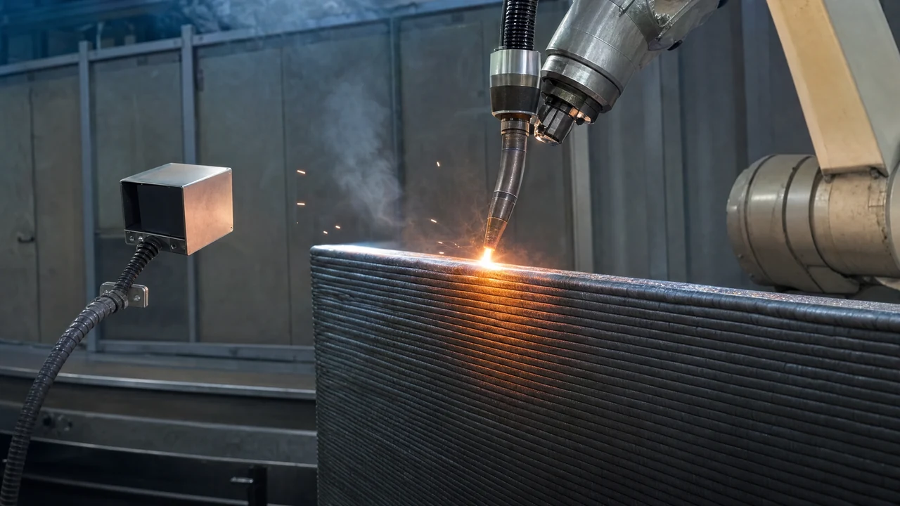
Interlayer temperature control is the single process parameter that determines whether a wire arc additive manufacturing (WAAM) build holds its geometry, its microstructure, and its mechanical properties from the first layer to the last. Deposit too fast without letting heat dissipate and a thin wall slumps or loses dimensional control; over-cool between layers and cycle time collapses along with any case for WAAM’s speed advantage over machining from billet. This guide covers how interlayer temperature affects a build, what limits published research and standards actually support, how to measure it in production, and how to build a closed-loop control strategy that does not rely on an operator’s stopwatch.
Key Takeaways
- Interlayer temperature — the substrate/layer temperature measured before the next bead — sets cooling rate, which sets microstructure, residual stress, and bead geometry through a WAAM build.
- There is no single universal interlayer temperature limit: published values for high-strength steel peak near 350°C before mechanical properties degrade, while titanium and aluminium alloys have different, alloy-specific windows.
- Contact thermocouples give a single accurate reading; non-contact pyrometers and thermal imaging cameras cover the full layer and can feed a robot controller for closed-loop dwell decisions.
- A dwell-time-only strategy (fixed wait between layers) wastes cycle time early in a build and under-cools late in a build as thermal mass accumulates — temperature feedback fixes both.
- The most common WAAM defects traced to interlayer temperature are bead slumping, inconsistent layer height, porosity, and microstructure that varies with build height.
- AWS D20.1, ASTM F3187, and ISO/ASTM 52900 frame documentation and terminology requirements; the qualified interlayer temperature limit itself must come from your own procedure qualification record, not a generic published number.
Table of Contents
- Why Interlayer Temperature Drives Bead Geometry, Microstructure, and Distortion
- Recommended Interlayer Temperature Limits by Material
- Standards and Terminology: AWS D20.1, ASTM F3187, and ISO/ASTM 52900
- Measuring Interlayer Temperature: Contact vs Non-Contact Methods
- Building a Closed-Loop Interlayer Temperature Control Strategy
- Common Failure Modes and How to Fix Them
- Validating and Documenting Interlayer Temperature for Audit
- Frequently Asked Questions
Why Interlayer Temperature Drives Bead Geometry, Microstructure, and Distortion
Every WAAM layer is a weld bead deposited on top of an already-hot part. As build height increases, the accumulated thermal mass changes the cooling conditions for every subsequent layer — a bead deposited on layer 3 sees a cold substrate and cools fast; the same programmed parameters on layer 40 land on a part that has been retaining heat for hours and cools far more slowly. Interlayer temperature is the measurement that captures this changing thermal state before it becomes a defect.
Three downstream effects trace directly back to interlayer temperature:
- Bead geometry. A hotter substrate means a wider, flatter, less predictable bead — weld pool viscosity drops and surface tension no longer holds the deposited profile. Beyond a material-specific threshold, walls slump sideways instead of building upward, and geometric accuracy is lost for the rest of the feature.
- Microstructure and mechanical properties. Cooling rate through the relevant transformation range sets grain size and phase fraction. In titanium alloys, faster cooling (lower interlayer temperature) produces finer alpha-lath structure and generally higher strength; in some high-strength steels, mechanical properties peak at a specific interlayer temperature and degrade on either side of it, not just above it.
- Residual stress and distortion. Layer-by-layer thermal cycling accumulates residual stress through the build. Controlling interlayer temperature — rather than letting it drift upward through the build — is one of the few in-process levers available to manage that stress before it shows up as distortion or, in low-transformation-temperature alloys, is deliberately used to induce compressive stress at the surface.
None of these effects are unique to exotic alloys. Even mild and low-alloy steel WAAM shows measurable strength variation across an interlayer temperature range of a few hundred degrees — the effect is smaller than in titanium, but it is not zero, and it is the reason coupon tests taken from the top and bottom of the same build can disagree.
Recommended Interlayer Temperature Limits by Material
There is no single interlayer temperature that applies across alloys, wire diameters, and deposition strategies — the number that matters is the one established in your own procedure qualification. Published research does, however, give usable starting windows and — more importantly — shows how differently each material family behaves.
| Material family | Reported behaviour | Practical implication |
|---|---|---|
| High-strength low-alloy steel | Mechanical properties peaked near 350°C in a published metal-cored-wire study; bead collapse observed near 600°C | Do not treat “as hot as tolerable” as the goal — there is an optimum, not just a ceiling |
| Titanium (Ti-6Al-4V) | Lower interlayer temperature and arc oscillation together improved geometric uniformity and mechanical consistency without a closed chamber | Titanium is the most cooling-rate-sensitive common WAAM alloy; tightest control pays off most here |
| Aluminium alloys (e.g. 5A06) | Higher interlayer temperature reduced porosity in one study by over 10% versus a lower-temperature bake | Aluminium’s porosity risk can run opposite to the “cooler is safer” intuition from steel |
| Low-transformation-temperature (LTT) steel cladding | Interlayer temperature strategy relative to the martensite transformation range determined whether residual stress was tensile or compressive | Here interlayer temperature is not a limit to respect — it is the active control variable for the desired outcome |
Do not import a number from a paper into a production WPS without qualification. Wire chemistry, shielding gas, deposition strategy (CMT, pulsed, cold-wire-assisted), and part geometry all shift where the real limit sits. Use published ranges to set your qualification test matrix, not your final production limit.
Standards and Terminology: AWS D20.1, ASTM F3187, and ISO/ASTM 52900
Wire arc additive manufacturing sits at the intersection of two standards traditions — fusion welding codes and additive manufacturing standards — and interlayer temperature documentation draws from both.
- AWS D20.1/D20.1M (Specification for Fabrication of Metal Components using Additive Manufacturing) covers design, procedure qualification, machine and operator qualification, fabrication requirements, and inspection for metal AM processes, including wire-fed arc systems. Interlayer/interpass temperature limits belong in the qualified procedure record under this specification, the same way interpass temperature belongs in a WPS under AWS D1.1 for conventional welding.
- ASTM F3187 (Standard Guide for Directed Energy Deposition of Metals) frames general DED process, setup, work practice, and — directly relevant here — system and process monitoring documentation expectations, applicable to arc-, laser-, and electron-beam-based DED.
- ISO/ASTM 52900 establishes the vocabulary — including the formal distinction between directed energy deposition processes and other AM process families — that the other two standards, and most WAAM research, now reference.
Because WAAM deposition is fusion arc welding, procedures qualified under an AM-specific standard commonly still sit inside a broader ISO 3834 welding quality management system for personnel qualification, equipment calibration, and non-conformance handling — WAAM does not exempt a fabricator from welding QMS obligations, it adds AM-specific requirements on top.
Measuring Interlayer Temperature: Contact vs Non-Contact Methods
| Method | Coverage | Robot integration | Typical use |
|---|---|---|---|
| Contact thermocouple (K-type, spot-welded) | Single point | Manual read or logged, not real-time feedback | Procedure qualification, baseline data capture |
| Handheld contact probe | Single point, operator-dependent | None | Manual spot checks between layers |
| Single-point infrared pyrometer | Single point, fixed or head-mounted | Can trigger a start/stop signal at one location | Simple pass/fail gating on repeatable geometry |
| Thermal imaging camera | Full layer surface | Feeds temperature-field data directly to the robot/PLC controller | Closed-loop dwell control, hot-spot detection on complex geometry |
Contact thermocouples remain the reference method for procedure qualification because their accuracy is well understood and traceable to a calibration standard — use them to establish the baseline interlayer temperature-versus-property relationship for a new WPS. They do not scale to production, though: a thermocouple measures one point, and a moving deposition head building a non-trivial geometry needs to know whether the hottest point on the layer — not an arbitrarily chosen point — is within limits.
This is where thermal imaging earns its place in a production cell. A camera reads the entire layer surface, flags the actual peak temperature location (which moves as geometry changes — overhangs, corners, and thin sections all retain heat differently from a straight wall), and outputs that reading directly to the robot or PLC as a control signal rather than a number an operator has to interpret and act on. HeatCam IR-S is built for exactly this embedded, always-on role inside a WAAM or DED cell, where a handheld pyrometer physically cannot keep pace with the deposition cycle.
A single-point pyrometer aimed at the wrong location on a complex geometry will read “cool enough” while a hidden hot spot elsewhere on the layer is well outside the qualified limit. If your build includes overhangs, corners, or varying wall thickness, single-point measurement is not sufficient — verify against a full-field thermal image before trusting a fixed pyrometer position.
Building a Closed-Loop Interlayer Temperature Control Strategy
- Establish the qualified window. Run procedure qualification coupons across a range of interlayer temperatures bracketing the values reported for your alloy family (see the table above), and test mechanical properties and defect rate at each. Record the accepted minimum and maximum, not just a single target value.
- Instrument the cell for full-layer measurement. Mount a thermal imaging camera with a clear view of the deposition zone, positioned to track the actual weld/layer surface through the build height, not a fixed distance that goes out of focus as the part grows.
- Set the control logic to gate on peak temperature, not average. Average layer temperature can mask a localised hot spot at a corner or overhang that is the actual defect risk. The robot’s next-layer trigger should wait for the peak reading to fall within the qualified window.
- Use active cooling to shorten — not eliminate — dwell. Forced air or shielding-gas-assisted cooling between layers reduces the wait time without a full process stop; for single-feature geometries, a dwell period after cooling assistance is still normal and expected, not a sign the process is failing.
- Log every layer’s interlayer temperature against the WPS window. This record is what closes the loop between the procedure qualification (step 1) and production evidence — see the documentation section below.
- Re-qualify when deposition strategy changes. A change in wire diameter, shielding gas, travel speed, or the addition of cold-wire assistance shifts the heat balance and invalidates the previous interlayer temperature window; treat it as a new procedure variable, not a tuning tweak.
Common Failure Modes and How to Fix Them
| Failure mode | Root cause | Fix |
|---|---|---|
| Wall slumping / loss of geometry | Interlayer temperature exceeded the material’s upper limit; weld pool loses surface tension control | Add active cooling or extend dwell before the next layer; re-verify against the qualified window, not a fixed timer |
| Inconsistent layer height requiring excess machining allowance | Interlayer temperature drifting upward uncontrolled through the build, changing bead width layer to layer | Move from fixed-dwell to temperature-triggered layer start; track the trend, not just pass/fail at each layer |
| Porosity increasing partway through a build | For some alloys, porosity risk rises as interlayer temperature drops below the alloy’s optimum — the opposite failure mode from slumping | Do not default to “cooler is always safer” — verify the alloy-specific direction of the effect during qualification |
| Mechanical test results vary by coupon height | Interlayer temperature was not held inside the qualified window through the full build, so cooling rate — and therefore microstructure — varied with height | Full-build temperature logging (not spot checks) so a failed coupon can be traced to the actual layer conditions that produced it |
| False confidence from a single-point sensor | Pyrometer or thermocouple was reading a location that was not the layer’s actual peak temperature | Move to full-field thermal imaging, or verify single-point sensor placement against a thermal image for each new geometry |
Validating and Documenting Interlayer Temperature for Audit
An AWS D20.1 or ASTM F3187 audit — or an ISO 3834 surveillance visit for a fusion-arc-based AM process — will ask for the same category of evidence a welding QMS auditor asks for on a conventional WPS: proof that the qualified parameter window was actually followed on the parts that were built, not just documented as a target. For interlayer temperature specifically, that means:
- The procedure qualification record showing the tested range and the accepted window, tied to the specific alloy, wire, and deposition strategy.
- A per-layer (or per-build, at minimum) temperature log demonstrating the qualified window was respected, with excursions flagged and dispositioned.
- Traceability from the temperature record to the specific build and, ideally, to the coupon or NDT result for that build — the same weld-map-style traceability expected for any structural welding record, adapted to a layer-indexed build instead of a joint-indexed structure.
Paper dwell-time logs (“waited 90 seconds between layers”) are not equivalent to interlayer temperature records for audit purposes — dwell time is a proxy, not the qualified parameter itself, and a fixed dwell does not account for the thermal mass changes described earlier in this guide.
Frequently Asked Questions
What is interlayer temperature in WAAM?
Interlayer temperature (also called interpass temperature) is the substrate or previously deposited layer temperature measured immediately before the next weld bead is deposited in wire arc additive manufacturing. It governs how heat accumulates through a build and directly affects bead geometry, cooling rate, microstructure, and residual stress.
What is the maximum interlayer temperature for WAAM steel builds?
Published research on high-strength low-alloy steel WAAM found mechanical properties peaked near 350°C interlayer temperature, with bead collapse and loss of geometric control observed near 600°C. Most production WAAM procedures for structural steel hold interlayer temperature between 100°C and 250°C, but the qualified limit must come from your own procedure qualification, not a generic figure.
Does interlayer temperature affect WAAM part strength?
Yes. Interlayer temperature controls cooling rate between passes, which sets grain size, phase fraction, and residual stress. In titanium WAAM, higher interlayer temperature promotes coarser alpha-lath microstructure and lower yield strength; in some steels it changes which transformation products form. Uncontrolled interlayer temperature is one of the main reasons two WAAM builds run on the same program produce different tensile results.
What is the difference between interlayer temperature and interpass temperature?
The terms are used interchangeably in WAAM literature. “Interpass temperature” originates in fusion welding codes such as AWS D1.1 and describes the temperature before the next weld pass on a joint. “Interlayer temperature” is the additive manufacturing-specific term for the same measurement applied at each deposited layer of a build. WAAM procedure documentation increasingly uses “interlayer” to align with ISO/ASTM 52900 terminology.
How do you measure interlayer temperature during a WAAM build?
Contact methods (K-type thermocouples spot-welded to the substrate, or handheld contact probes) give a single accurate point reading but cannot follow a moving deposition head or scale to full-layer coverage. Non-contact methods — single-point pyrometers or thermal imaging cameras — read the full layer surface and can trigger the robot controller directly, which is what closed-loop dwell control requires.
Can interlayer temperature be controlled without stopping the build?
Partially. Forced-air or CO2 cooling between layers reduces dwell time without a full stop, and some cells sequence deposition across multiple features so one cools while another is built. But for single-wall or single-feature geometries, a dwell (idle) period is usually still required once interlayer temperature exceeds the qualified limit — the goal of monitoring is to make that dwell as short as it needs to be, not to eliminate it.
What defects result from uncontrolled interlayer temperature in WAAM?
The most common are bead slumping and loss of wall geometry (excess heat accumulation), inconsistent layer height requiring downstream machining allowance, porosity from insufficient time for gas evolution, and inconsistent microstructure through the build height that produces inconsistent mechanical test results from coupons cut at different layers.
Which standards apply to WAAM interlayer temperature control?
AWS D20.1/D20.1M covers fabrication, qualification, and inspection requirements for metal additive manufacturing including wire-fed arc processes. ASTM F3187 provides a general guide for the directed energy deposition process and its monitoring documentation. ISO/ASTM 52900 defines the terminology used across both. Because WAAM is fusion-welding-based, an ISO 3834 quality management system is often layered on top for procedure and personnel qualification.
Further reading on the underlying research: ORNL’s work on thermal process monitoring for wire-arc additive manufacturing using IR cameras, NIST IR 8538 on in-process monitoring for additive manufacturing, TWI’s overview of arc-based additive manufacturing, ASME’s additive manufacturing resource hub, a ScienceDirect review of WAAM hardware, monitoring, and process control, and peer-reviewed interlayer temperature studies on high-strength metal-cored wire steel and Inconel 718.
Related on Therness: Wire Arc Additive Manufacturing (WAAM) in titanium aerospace applications, WAAM monitoring camera setup, field of view, and data integration, interpass temperature measurement and control in conventional welding, and welding heat input calculation for quality control.
Bring Full-Field Thermal Feedback to Your WAAM Cell
Therness HeatCam IR-S reads the entire layer surface in real time and feeds interlayer temperature directly to your robot controller — so dwell time is driven by data, not a fixed timer.
Talk to an Engineer See WAAM monitoring on ThernessTherness solution: Welding monitoring system — Every weld inspected in the cycle, with defect flags and the ISO 3834 / ISO 17635 evidence kept per weld.
Frequently Asked Questions
What is interlayer temperature in WAAM?
Interlayer temperature (also called interpass temperature) is the substrate or previously deposited layer temperature measured immediately before the next weld bead is deposited in wire arc additive manufacturing. It governs how heat accumulates through a build and directly affects bead geometry, cooling rate, microstructure, and residual stress.
What is the maximum interlayer temperature for WAAM steel builds?
Published research on high-strength low-alloy steel WAAM found mechanical properties peaked near 350°C interlayer temperature, with bead collapse and loss of geometric control observed near 600°C. Most production WAAM procedures for structural steel hold interlayer temperature between 100°C and 250°C, but the qualified limit must come from your own procedure qualification, not a generic figure.
Does interlayer temperature affect WAAM part strength?
Yes. Interlayer temperature controls cooling rate between passes, which sets grain size, phase fraction, and residual stress. In titanium WAAM, higher interlayer temperature promotes coarser alpha-lath microstructure and lower yield strength; in some steels it changes which transformation products form. Uncontrolled interlayer temperature is one of the main reasons two WAAM builds run on the same program produce different tensile results.
What is the difference between interlayer temperature and interpass temperature?
The terms are used interchangeably in WAAM literature. "Interpass temperature" originates in fusion welding codes such as AWS D1.1 and describes the temperature before the next weld pass on a joint. "Interlayer temperature" is the additive manufacturing-specific term for the same measurement applied at each deposited layer of a build. WAAM procedure documentation increasingly uses "interlayer" to align with ISO/ASTM 52900 terminology.
How do you measure interlayer temperature during a WAAM build?
Contact methods (K-type thermocouples spot-welded to the substrate, or handheld contact probes) give a single accurate point reading but cannot follow a moving deposition head or scale to full-layer coverage. Non-contact methods — single-point pyrometers or thermal imaging cameras — read the full layer surface and can trigger the robot controller directly, which is what closed-loop dwell control requires.
Can interlayer temperature be controlled without stopping the build?
Partially. Forced-air or CO2 cooling between layers reduces dwell time without a full stop, and some cells sequence deposition across multiple features so one cools while another is built. But for single-wall or single-feature geometries, a dwell (idle) period is usually still required once interlayer temperature exceeds the qualified limit — the goal of monitoring is to make that dwell as short as it needs to be, not to eliminate it.
What defects result from uncontrolled interlayer temperature in WAAM?
The most common are bead slumping and loss of wall geometry (excess heat accumulation), inconsistent layer height requiring downstream machining allowance, porosity from insufficient time for gas evolution, and inconsistent microstructure through the build height that produces inconsistent mechanical test results from coupons cut at different layers.
Which standards apply to WAAM interlayer temperature control?
AWS D20.1/D20.1M covers fabrication, qualification, and inspection requirements for metal additive manufacturing including wire-fed arc processes. ASTM F3187 provides a general guide for directed energy deposition process and monitoring documentation. ISO/ASTM 52900 defines the terminology used across both. Because WAAM is fusion-welding-based, an ISO 3834 quality management system is often layered on top for procedure and personnel qualification.