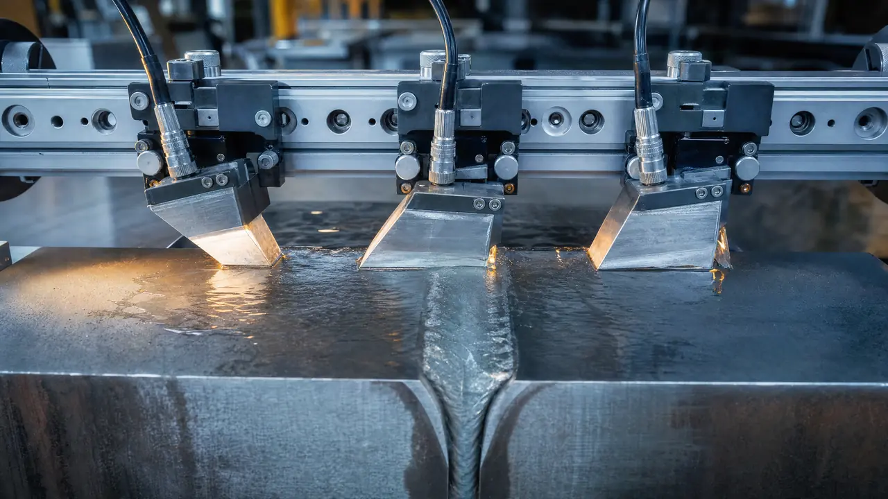
Acoustic emission testing finds active weld defects by listening for the transient elastic stress waves a discontinuity releases the moment it forms or grows — a crack extending, a hydrogen-induced flaw initiating in the heat-affected zone, or slag breaking loose — rather than mapping static flaws after the fact the way radiographic or ultrasonic testing does. For welding engineers and quality managers running continuous or high-value fabrication, that real-time signal is the appeal: AE can flag a growing discontinuity while the joint is still being welded or while a finished vessel is under a pressure test, well before a scheduled volumetric inspection would ever see it.
This guide covers what acoustic emission (AE) actually measures in a weld, the standards that govern in-process and pressure-test AE examination, how to set up sensors and run a procedure correctly, the failure modes that produce bad calls in the field, and where AE fits alongside volumetric NDT and in-process thermal monitoring on a real fabrication line.
Key takeaways
- AE detects the stress waves released by an active discontinuity — a crack extending or a flaw initiating — not a static, already-formed defect sitting quietly under no load.
- ASTM E749/E749M governs AE monitoring during continuous welding; ASME BPVC Section V, Article 12 governs AE examination of metal pressure vessels during a pressure test — two different applications of the same physics.
- The Kaiser and Felicity effects are the interpretive backbone of AE: emission returning below a material’s prior stress maximum is the signature of a genuinely growing flaw.
- Sensor spacing is set by attenuation and triangulation geometry, verified with a Hsu-Nielsen pencil-lead break before monitoring starts, not by convenience.
- AE is a screening and location method, not a sizing method — any location it flags still needs RT, UT, MT, or PT to characterize and accept or reject the indication.
- Background noise (arc interference, mechanical rattle, fluid flow) is the dominant source of false AE calls; filtering, guard sensors, and calibration control it.
- AE and in-process thermal monitoring answer different questions on the same weld — one reads the defect forming, the other reads the process conditions that produced it — and pairing them gives redundant, independent evidence for the same joint.
Table of contents
- What acoustic emission testing measures in a weld
- When to choose AE over RT, UT, MT, or PT
- Standards governing weld acoustic emission examination
- Equipment and sensor array setup
- Step-by-step AE procedure for welds
- Common failure modes and how to fix them
- Where AE fits in a broader weld quality program
What acoustic emission testing measures in a weld
Every other NDT method used on welds — radiographic, ultrasonic, magnetic particle, penetrant, eddy current — interrogates a joint that has already stopped changing. A technician sends energy in (X-rays, sound, a magnetic field) and reads what comes back. Acoustic emission works the opposite way: the part itself generates the signal, and the sensor only listens. When a discontinuity forms or grows — a crack tip advancing, a hydrogen-induced flaw initiating in the heat-affected zone, an inclusion debonding from the matrix — the sudden local release of strain energy sends an ultrasonic stress wave through the material, and a piezoelectric sensor coupled to the surface converts that wave into an electronic signal.
That distinction — active versus static — is what defines both AE’s value and its limits. AE can catch a discontinuity in the act of forming, during welding or during a post-weld load application, which no volumetric method can do without stopping and re-scanning repeatedly. But AE has nothing to say about a discontinuity that formed earlier and is now sitting quietly under no load: a crack that produced emission last week during welding but is dormant today will not emit again unless it is reloaded past its previous stress state.
That reload behavior has a name: the Kaiser effect. A material stays acoustically quiet when stress is reapplied below the highest level it has previously experienced, and only emits again once that prior maximum is exceeded. The inverse — emission returning at a lower stress than the previous cycle — is called the Felicity effect, expressed as the Felicity ratio (the stress at which emission resumes, divided by the previous maximum stress). A Felicity ratio below 1.0 is the classic signature analysts look for to flag a discontinuity that is actively growing rather than stable, which is why AE data is interpreted through loading history, not through a single snapshot.
When to choose AE over RT, UT, MT, or PT
AE is not a substitute for radiographic, ultrasonic, magnetic particle, or penetrant testing — it answers a different question. RT and UT size and characterize a flaw once welding is done; MT and PT find surface-breaking indications on a finished, static joint. AE instead tells you where and roughly when something is actively happening, in real time, across an area that would otherwise require repeated static scans to cover.
That makes AE the right tool in two specific situations. First, in-process monitoring during continuous welding (submerged arc, electroslag, and similar processes covered by ASTM E749/E749M), where thermal stress from the weld itself can drive cracking while the joint is still hot and where stopping to run a volumetric scan mid-weld is impractical. Second, pressure-test screening of finished vessels and piping (ASME BPVC Section V, Article 12), where reapplying load during a hydrostatic or pneumatic test reveals which welds — out of dozens on a large vessel — are still acoustically active and therefore deserve a focused follow-up scan, instead of blanket re-inspecting every joint.
Outside those two windows, AE adds little. A finished, unloaded weld that has already passed its pressure test gives AE nothing to listen to, which is exactly why fabrication codes that call for AE still require a conventional NDT method to close out the acceptance decision.
Standards governing weld acoustic emission examination
| Standard | Scope | Where it applies |
|---|---|---|
| ASTM E749/E749M | Acoustic emission monitoring during continuous welding | In-process monitoring of weldments and the heat-affected zone while fusion and solidification are still occurring |
| ASME BPVC Section V, Article 12 | Acoustic emission examination of metallic pressure vessels during pressure testing | Post-weld hydrostatic/pneumatic testing of ASME-code pressure vessels and piping |
| EN 13554 | General principles of acoustic emission testing | European application documents and procedure development for AE across industries |
| ISO 9712 personnel certification | Qualification and certification of NDT personnel, including the AE method | Level I-III competency requirements for AE operators on code-governed work |
These four cover the load-bearing decisions in any AE program: E749/E749M sets the in-process procedure, Article 12 sets the pressure-test procedure, EN 13554 sets the general methodology European fabricators build application documents against, and ISO 9712 (alongside the ASNT SNT-TC-1A recommended practice) sets who is qualified to run and sign off on the test.
Equipment and sensor array setup
An AE system has three functional layers: sensors, signal conditioning, and location/analysis software.
Sensors are piezoelectric transducers, typically resonant in the 100 kHz-1 MHz range for metal weld applications — high enough to reject low-frequency mechanical noise, low enough to avoid the attenuation that kills high-frequency signals over any real travel distance. Where the mounting surface is too hot for direct sensor contact (common during in-process monitoring per E749/E749M), a waveguide — a metal rod acoustically coupled between the hot surface and a sensor mounted further away — carries the signal out to where the transducer can survive.
Sensor spacing is set by two competing constraints: wide enough spacing to cover the area of interest with the fewest sensors, tight enough that attenuation does not drop a genuine event below the detection threshold before it reaches at least three sensors — the minimum needed to triangulate a source location from arrival-time differences. Attenuation is material- and geometry-dependent, so spacing is verified empirically with a Hsu-Nielsen source (a 0.5 mm pencil lead broken against the surface at a fixed angle), not assumed from a table.
Signal conditioning — preamplification close to the sensor, followed by bandpass filtering — separates genuine stress-wave events from the two dominant noise sources on a fabrication floor: low-frequency mechanical noise (rattle, friction, fluid flow) and electromagnetic interference from the welding arc itself, which is a serious problem specifically for in-process AE monitoring and is one reason E749/E749M procedures specify shielding and grounding practice alongside sensor placement.
Step-by-step AE procedure for welds
- Define the zone and select the standard. In-process monitoring during welding follows ASTM E749/E749M; post-weld pressure-test screening follows ASME BPVC Section V, Article 12. The zone of interest — the weld and heat-affected zone, or the full pressure boundary — determines sensor count and layout.
- Mount sensors and waveguides. Couple sensors (directly or via waveguide) around the zone at spacing set by prior attenuation testing, with guard sensors placed to reject noise arriving from outside the zone of interest.
- Verify with a Hsu-Nielsen source. Break a pencil lead at known reference points and confirm the system locates the simulated source within the procedure’s specified accuracy before monitoring begins.
- Set the detection threshold. Establish a threshold above the ambient background noise floor recorded on the actual part, in the actual environment — not a generic default — so genuine low-amplitude events are not lost in noise.
- Monitor through the load or process event. Record continuously through the weld pass (E749/E749M) or through the pressure-test hold and any pressure increments (Article 12), capturing hit count, amplitude, arrival time, and location for every threshold-crossing event.
- Evaluate against the Kaiser/Felicity framework. Compare emission onset against prior load history; a Felicity ratio below the procedure’s specified limit is the trigger for follow-up.
- Dispatch a volumetric or surface method to flagged locations. Send RT, UT, MT, or PT to every AE-flagged source location to characterize, size, and make the accept/reject decision the code requires — AE data alone is not an acceptance basis.
- Report. Document sensor layout, calibration source results, threshold settings, all located events with amplitude and Felicity ratio, and the disposition of each flagged location, per the governing standard’s reporting requirements.
Common failure modes and how to fix them
Background noise masking or mimicking real events. Arc interference during in-process monitoring, plus mechanical rattle, fluid flow, or rubbing contact anywhere near the sensors, is the single largest source of false AE calls. Fix: bandpass filtering tuned to the application, guard sensors that reject signals originating outside the zone of interest, and a noise floor measured on the actual setup before every job — not carried over from a different part or procedure.
Sensor spacing exceeding the effective attenuation range. A sensor array laid out by convenience rather than by measured attenuation will miss events between sensors or fail to triangulate a location accurately. Fix: run attenuation testing with a Hsu-Nielsen source on the actual part geometry and material before finalizing spacing, not after.
Treating any recorded hit as a defect. Raw hit count includes benign sources — friction, minor surface rubbing, electrical interference that leaks past filtering — alongside genuine discontinuity growth. Fix: apply the Kaiser/Felicity framework and amplitude/location clustering before calling any indication a defect; a single unqualified hit is not an acceptance criterion.
Skipping the follow-up volumetric scan. AE gives location and timing, not size or classification, and a location flagged by AE with no RT/UT/MT/PT follow-up leaves the actual accept/reject decision unmade. Fix: build the follow-up scan into the procedure as a mandatory step, not an optional one.
Poor coupling or waveguide contact. A loose sensor or a poorly coupled waveguide attenuates or completely blocks a genuine signal before it ever reaches the transducer, producing false negatives rather than false positives. Fix: verify coupling with the Hsu-Nielsen calibration source at every sensor position, not just at the array level, before monitoring starts.
Where AE fits in a broader weld quality program
AE, volumetric/surface NDT, and in-process thermal monitoring answer three different questions about the same weld, and a mature quality program uses all three rather than picking one. Radiographic, ultrasonic, magnetic particle, and penetrant testing confirm what the finished joint looks like. AE confirms when and where a discontinuity was actively forming or growing, during welding or during a pressure test. In-process thermal monitoring confirms the process conditions — heat input, cooling rate, parameter drift — that produced (or avoided) the defect in the first place.
That third layer is where real-time thermal weld monitoring does work AE cannot: AE tells you a crack is forming, but only thermal data tells you why — an out-of-window cooling rate, an arc parameter drift, an interpass temperature excursion — which is the information that lets a welding engineer correct the process before the next joint repeats the same failure. Fabricators running both AE and thermal monitoring on high-value welds get two independent, physically distinct signals on the same joint: a stress-wave record of defect activity and a thermal record of the process that caused it, feeding the same traceability file. For teams building out a broader thermography-based NDT program alongside acoustic or volumetric methods, that pairing is also where AI-assisted defect classification on systems like Therness HeatCore AI adds the most value — correlating thermal signatures against known defect classes in the same window AE or post-weld NDT would otherwise flag in isolation.
For fabricators evaluating which methods belong in a given procedure, related guides cover the volumetric and surface methods AE is typically paired with: radiographic testing acceptance criteria, phased array ultrasonic testing, magnetic particle testing, liquid penetrant testing, and eddy current testing — plus welding process consulting for fabricators building an AE or multi-method NDT procedure from scratch.
Frequently asked questions
What is acoustic emission testing used for in welding? AE detects the transient elastic stress waves released when a discontinuity grows — a crack extending, slag breaking loose, or hydrogen-induced cracking initiating in the heat-affected zone. Sensors mounted on the part pick up these waves as they happen, so AE catches active, growing flaws during welding or during a post-weld pressure test rather than mapping static defects after the fact.
Can acoustic emission testing detect defects during welding, or only after? Both, depending on the procedure. ASTM E749/E749M covers AE monitoring in-process, while the weld is still being deposited and cooling, to catch cracking driven by thermal stress. ASME BPVC Section V, Article 12 instead applies AE during a post-weld hydrostatic or pneumatic pressure test, when stress reapplied to the finished joint reveals discontinuities that are still active.
What is the Kaiser effect and why does it matter for acoustic emission testing? The Kaiser effect is the observation that a material stays acoustically quiet when reloaded below a stress level it has already experienced, and only emits again once that prior maximum is exceeded. The inverse — emission returning at a lower stress, called the Felicity effect — signals a discontinuity that is actively growing and worth flagging.
What standards govern acoustic emission testing of welds? ASTM E749/E749M covers AE monitoring during continuous welding. ASME BPVC Section V, Article 12 covers AE examination of metal pressure vessels during pressure testing. EN 13554 sets the general principles for AE testing in Europe. ISO 9712 and ASNT SNT-TC-1A both define acoustic emission as a certifiable NDT method with Level I-III personnel qualification.
How is an acoustic emission sensor array set up on a weldment? Piezoelectric sensors are coupled to the part around the zone of interest, spaced so arrival-time differences can triangulate a source location, then verified with a Hsu-Nielsen pencil-lead break at known points before monitoring starts. Waveguides carry signal off hot surfaces near the weld, and a preamplifier plus bandpass filter separate genuine stress-wave signals from mechanical and electrical noise.
What are the main limitations of acoustic emission testing for welds? AE only detects discontinuities that are actively growing at the moment of the test — a static crack producing no stress-wave activity under load is invisible to it. Attenuation limits sensor spacing on long or complex welds, and background noise from arc interference, mechanical rattle, or fluid flow can mask or mimic genuine defect signals without careful filtering and calibration.
Does acoustic emission testing replace radiographic or ultrasonic testing of welds? No. AE flags where and roughly when a discontinuity is active during welding or a pressure test, but it does not size, classify, or characterize the flaw the way radiographic or ultrasonic testing does. Codes that require AE monitoring still call for a volumetric or surface method to confirm and evaluate any location AE identifies.
Where does acoustic emission testing fit alongside in-process thermal weld monitoring? The two verify different physics and normally run alongside each other. Thermal monitoring tracks heat input, cooling rate, and process parameters as the weld is made — the conditions that produce a defect. AE tracks the stress-wave signature of a discontinuity actually forming or growing, giving a second, independent confirmation channel on the same weld.
Further reading on acoustic emission fundamentals is available from TWI’s acoustic emission testing guide, the Center for NDE acoustic emission introduction at Iowa State University, the NDE-ED acoustic emission applications reference, the National Board of Boiler and Pressure Vessel Inspectors’ AE examination overview, ASNT’s Level III certification requirements for acoustic emission testing, and a peer-reviewed study on real-time weld monitoring using air-coupled ultrasonics and acoustic emission published in the International Journal of Advanced Manufacturing Technology.
Pair active-defect detection with real-time process visibility
AE tells you a discontinuity is forming. Therness tells you why — real-time thermal monitoring that tracks heat input, cooling rate, and parameter drift while the joint is being welded, feeding the same traceability record as your AE and NDT program.
Talk to ThernessTherness solution: Welding monitoring system — Every weld inspected in the cycle, with defect flags and the ISO 3834 / ISO 17635 evidence kept per weld.
Frequently Asked Questions
What is acoustic emission testing used for in welding?
Acoustic emission (AE) testing detects the transient elastic stress waves released when a discontinuity grows — a crack extending, slag breaking loose, or hydrogen-induced cracking initiating in the heat-affected zone. Sensors mounted on the part pick up these waves as they happen, so AE is used to catch active, growing flaws during welding or during a post-weld pressure test rather than mapping static defects after the fact.
Can acoustic emission testing detect defects during welding, or only after?
Both, depending on the procedure. ASTM E749/E749M covers AE monitoring in-process, while the weld is still being deposited and cooling, to catch cracking driven by thermal stress. ASME BPVC Section V, Article 12 instead applies AE during a post-weld hydrostatic or pneumatic pressure test, when stress reapplied to the finished joint reveals discontinuities that are still active.
What is the Kaiser effect and why does it matter for acoustic emission testing?
The Kaiser effect is the observation that a material stays acoustically quiet when reloaded below a stress level it has already experienced, and only emits again once that prior maximum is exceeded. It is the basis for interpreting AE data: emission that returns at a lower stress than the last cycle (the opposite behavior, called the Felicity effect) signals a discontinuity that is actively growing and worth flagging.
What standards govern acoustic emission testing of welds?
ASTM E749/E749M covers AE monitoring during continuous welding. ASME BPVC Section V, Article 12 covers AE examination of metal pressure vessels during pressure testing. EN 13554 sets the general principles for acoustic emission testing in Europe. ISO 9712 and ASNT SNT-TC-1A both define acoustic emission as a certifiable NDT method with Level I-III personnel qualification.
How is an acoustic emission sensor array set up on a weldment?
Piezoelectric sensors are coupled to the part around the zone of interest, spaced so that the arrival-time difference between sensors can triangulate a source location, then verified with a Hsu-Nielsen pencil-lead break at known points before monitoring starts. Waveguides carry the signal off hot surfaces near the weld, and a preamplifier and bandpass filter separate genuine stress-wave signals from mechanical and electrical noise on the line.
What are the main limitations of acoustic emission testing for welds?
AE only detects discontinuities that are actively growing at the moment of the test — a static crack that produces no stress-wave activity under the applied load is invisible to it. Attenuation limits sensor spacing on long or geometrically complex welds, and background noise from arc interference, mechanical rattle, or fluid flow can mask or mimic genuine defect signals if filtering and calibration are not done carefully.
Does acoustic emission testing replace radiographic or ultrasonic testing of welds?
No. AE flags where and roughly when a discontinuity is active during welding or a pressure test, but it does not size, classify, or characterize the flaw the way radiographic or ultrasonic testing does. Fabrication codes that require AE monitoring still call for a volumetric or surface method — RT, UT, MT, or PT — to confirm and evaluate any location AE identifies.
Where does acoustic emission testing fit alongside in-process thermal weld monitoring?
The two methods verify different physics and normally run alongside each other rather than replacing one another. Thermal monitoring tracks heat input, cooling rate, and process parameters as the weld is made — the conditions that produce a defect. AE tracks the stress-wave signature of a discontinuity actually forming or growing, giving a second, independent confirmation channel on the same weld.