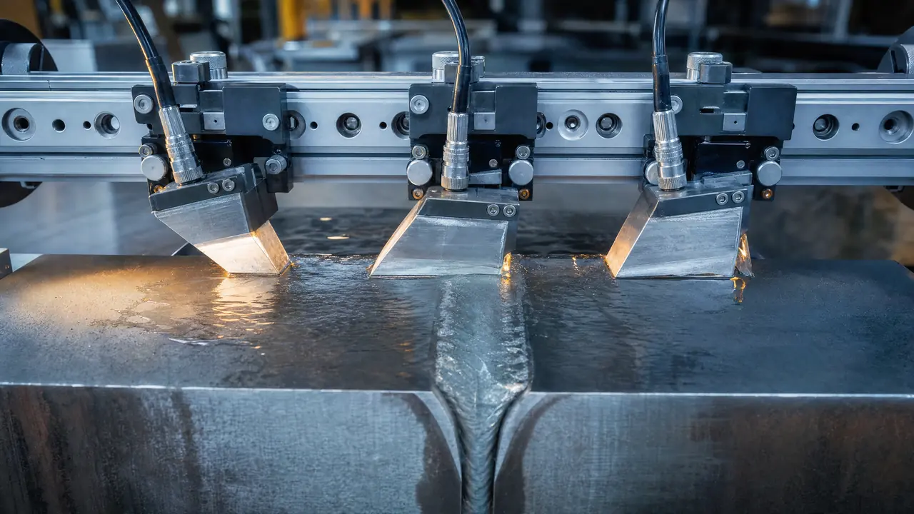
Eddy current testing (ECT) finds surface and near-surface weld defects by reading how the joint distorts an induced electromagnetic field — no couplant, no radiation permit, and no particle cleanup, which is why it shows up on tube mills, pipeline tie-in crews, and in-service inspection contracts where speed and repeatability matter as much as sensitivity. For welding engineers and quality managers deciding between eddy current, magnetic particle, and penetrant methods, the choice usually comes down to base-metal conductivity, surface condition, and whether the inspection has to run inline without stopping production.
This guide covers what ECT actually measures in a weld, the standards that govern it, how to select probes and set up a procedure, the failure modes that produce bad calls in the field, and how ECT fits alongside other NDT and in-process monitoring methods on a welded fabrication line.
Key takeaways
- ECT induces eddy currents in a conductive part and reads impedance changes caused by surface and near-surface discontinuities — it does not need the part to be magnetic, unlike MT.
- Sensitivity is governed by skin depth, which is set by probe frequency and the material’s conductivity and permeability — higher frequency means shallower, more surface-sensitive detection.
- ISO 17643 and ASME Section V, Article 8 are the two standards fabricators most often work to for weld eddy current examination.
- Lift-off variation is the dominant source of false calls; procedures control it with fixed probe geometry, calibration blocks, and phase-analysis instrumentation.
- ECT is the only common surface NDT method that works equally well on ferromagnetic and non-ferromagnetic metals, making it the default choice for stainless and aluminum welds where MT cannot be used at all.
- Reference standards with EDM notches of known depth are what make an ECT “pass” defensible in an audit, the same role a calibration block plays in ultrasonic testing.
- ECT complements, not replaces, in-process thermal weld monitoring — one verifies the finished joint’s surface integrity, the other verifies the process that produced it.
Table of contents
- What eddy current testing verifies in a weld
- When to choose ECT over MT, PT, or UT
- Standards governing weld eddy current examination
- Equipment and probe selection
- Step-by-step ECT procedure for welds
- Common failure modes and how to fix them
- Validating and verifying ECT results
- Where ECT fits in a broader weld quality program
What eddy current testing verifies in a weld
ECT works by driving an alternating current through a coil in the probe, which induces circulating “eddy” currents in the conductive metal underneath it. Those eddy currents generate their own opposing magnetic field, which feeds back into the probe coil and changes its impedance. A surface-breaking or near-surface crack, porosity cluster, or lack-of-fusion line interrupts the eddy current flow, and the probe reads that interruption as a change in impedance — plotted on an instrument screen as a signal that moves in amplitude and phase.
Two properties define what a given setup can and cannot see. The first is skin depth — the eddy currents concentrate near the surface and decay exponentially with depth, so a discontinuity buried below the effective penetration depth produces little or no signal. The second is material response: because the technique depends only on electrical conductivity, not magnetism, it works identically on carbon steel, stainless steel, aluminum, and copper alloys, unlike magnetic particle testing, which needs a ferromagnetic part to hold a field at all.
In a welded joint, ECT is applied to the weld cap, toe, and adjacent heat-affected zone to catch surface-breaking cracks (hydrogen cracking, toe cracks, crater cracks), and to detect near-surface porosity or lack-of-fusion close enough to the surface to fall inside the skin-depth window. It is routinely run on the as-welded surface without grinding, though very rough as-deposited surfaces reduce signal reliability and may require light dressing first.
When to choose ECT over MT, PT, or UT
No single surface method is correct for every joint. The decision usually turns on four variables: base-metal magnetism, surface accessibility and condition, coating presence, and whether the inspection needs to run at production speed.
| Factor | Favors ECT | Favors MT | Favors PT |
|---|---|---|---|
| Base metal | Any conductive metal, including stainless/aluminum | Ferromagnetic only (carbon/low-alloy steel) | Any non-porous solid |
| Surface coating | Works through thin, non-conductive coatings | Requires bare or thinly coated ferromagnetic surface | Requires bare, clean surface |
| Speed / automation | Fast, automatable, no consumables or cleanup | Moderate — magnetizing + media application/removal | Slow — dwell time for penetrant + developer |
| Result type | Quantitative electronic signal, permanent digital record | Visual indication, judgment-dependent | Visual indication, judgment-dependent |
| Depth sensitivity | Surface and near-surface only (skin-depth limited) | Surface and shallow subsurface | Surface-breaking only |
| Best on | Tube/pipe welds, stainless and aluminum fabrication, in-service inspection | Carbon steel fillet and groove welds, structural steel | Castings, non-magnetic alloys, leak-path detection |
If the joint is on austenitic stainless or aluminum, ECT and PT are the realistic surface-method choices since MT is off the table entirely — see the magnetic particle testing (MT) of welds procedure for where MT does apply. Where speed and a permanent digital trace matter more than raw sensitivity to fine surface-breaking cracks, ECT usually wins over liquid penetrant testing (PT) of welds, which needs dwell time and produces only a visual, non-quantitative call. For volumetric coverage of the weld interior, ECT is not a substitute at all — that is the job of radiography or phased array ultrasonic testing (PAUT).
ECT and MT are frequently specified together on carbon-steel pressure piping: MT for its established sensitivity to fine surface cracks on ferromagnetic steel, ECT for the near-surface coverage MT can miss and for the parts of the fabrication (stainless fittings, dissimilar-metal transitions) where MT cannot be used.
Standards governing weld eddy current examination
Three documents cover most of the procedures a welding or quality engineer will encounter:
| Standard | Scope | Applies to |
|---|---|---|
| ISO 17643 | Eddy current testing of welds by complex-plane analysis | General weld examination, primarily ferritic materials, extendable to non-ferritic by application standard |
| ASME BPVC Section V, Article 8 | Eddy current examination requirements for ASME-code pressure equipment | Boiler and pressure vessel welds fabricated under the ASME code |
| ASTM E309 | Eddy current examination of ferromagnetic steel tubular products using magnetic saturation | Welded and seamless ferromagnetic tube/pipe, common on tube-mill welds |
| ASTM E243 | Electromagnetic examination of copper and copper-alloy tubes | Non-ferrous welded and drawn tube |
ISO 17643 is the direct successor to the earlier European EN 1711 complex-plane-analysis standard, which it has superseded; specifications still referencing EN 1711 on older drawings should be treated as equivalent to the current ISO 17643 scope. Personnel performing code-governed ECT need to hold a current qualification — see the ISO 9712 NDT personnel certification overview for how the eddy current method fits into the broader NDT personnel certification scheme, alongside the ASNT SNT-TC-1A route used on many US contracts.
Equipment and probe selection
Probe type is the first decision. Absolute probes read the total impedance at a point and are simple to interpret but sensitive to slow material variations (like general conductivity drift); differential probes compare two adjacent coils and cancel out that slow drift, making them better at picking a sharp, localized crack signal out of background noise. Pencil probes suit manual scanning of accessible weld caps and toes; array probes, which pack multiple coil elements into a single scan head, cover a wider swath per pass and are standard on automated tube-mill and pipeline girth-weld inspection.
Frequency selection sets skin depth, and therefore sets what the probe can and cannot see. Higher frequency concentrates sensitivity closer to the surface — good for fine surface-breaking cracks, poor for anything slightly subsurface. Lower frequency penetrates deeper but loses resolution on small, tight defects. Procedures typically specify a primary test frequency plus a secondary frequency for mixed-mode analysis, so the operator can separate a lift-off signal from a genuine near-surface flaw by comparing how each behaves at the two frequencies.
Reference (calibration) standards carry electro-discharge-machined (EDM) notches of a defined depth, length, and width, cut into a block of the same or a metallurgically similar material to the production weld. The instrument is calibrated against these notches before scanning and re-verified at defined intervals during the shift; a signal from the production weld is judged against the calibrated notch response, not against an operator’s subjective read of the trace.
Step-by-step ECT procedure for welds
- Confirm the written procedure and personnel qualification against the governing code (ISO 17643 or ASME Section V, Article 8) before starting — probe type, frequency, scan pattern, and acceptance criteria all have to be specified in advance, not decided on the shop floor.
- Prepare the surface. Remove spatter, heavy scale, and loose slag from the weld cap, toes, and adjacent HAZ. Light, adherent mill scale or thin coatings are usually acceptable if the procedure’s lift-off tolerance accounts for them; heavy or uneven coating is not.
- Calibrate against the reference standard, setting probe frequency, gain, and phase rotation so the EDM notch signal reaches a defined screen height and phase angle, per the procedure.
- Set and hold scan speed and probe orientation as specified — differential probes especially are sensitive to scan direction relative to a linear defect, so procedures typically require at least two scan passes at different orientations across a weld toe.
- Scan the weld cap, toes, and HAZ in overlapping passes covering 100% of the required examination volume, maintaining probe contact and consistent lift-off throughout.
- Flag and re-verify any indication exceeding the recording threshold — re-scan at a different angle or frequency to confirm it is a real discontinuity signal and not lift-off, edge effect, or an artifact from surface condition.
- Size and disposition confirmed indications against the acceptance criteria in the governing code or contract, and record instrument settings, calibration data, indication location, and disposition in the examination report.
Common failure modes and how to fix them
Lift-off masking a real defect. A probe riding unevenly over a weld toe, or scanning across a coating-thickness step, produces a lift-off signal that can bury a genuine crack indication. Fix: hold consistent probe-to-surface contact with a fixture or guide where possible, and use phase-analysis instrumentation that separates lift-off phase from defect phase rather than relying on amplitude alone.
Edge effect at the weld toe. The abrupt geometry change at a weld toe or plate edge produces a strong signal that can look like — or hide — a real crack. Fix: procedures should define a standoff distance from geometric edges and specify how edge-effect signals are distinguished from crack indications, typically through phase-angle comparison against the calibration notch.
Permeability variation in the heat-affected zone masking real signals. On carbon steel, the HAZ’s magnetic permeability can vary from the base metal enough to produce a background signal that swamps a small defect indication. Fix: run a permeability-variation check as part of setup, and consider a lower test frequency or a probe design less sensitive to permeability noise when HAZ variation is significant.
Calibration block material mismatch. A reference standard cut from a different alloy than the production part gives a miscalibrated response — conductivity varies enough between alloys to shift the baseline signal. Fix: match the reference block material to the production part’s alloy and heat-treatment condition, not just its nominal grade.
Frequency chosen without checking skin depth against defect depth. A frequency set too high for the material can completely miss a near-surface defect that the specification intended to catch. Fix: calculate or verify skin depth for the actual test frequency and material conductivity before finalizing the procedure, not after a missed defect surfaces downstream.
Validating and verifying ECT results
An ECT “pass” is only as defensible as the calibration behind it. Verification should run at three levels:
- Pre-scan and periodic calibration against the EDM-notched reference standard, re-checked at defined intervals through the shift and whenever probe, cable, or instrument settings change.
- Independent confirmation of borderline or ambiguous indications, either with a second scan at a different frequency/orientation or with a complementary method (MT or PT where applicable) before an indication is accepted or rejected.
- Correlation studies where feasible — cutting out and sectioning a sample of flagged and unflagged locations periodically to confirm the procedure’s detection and false-call rates match what the acceptance criteria assume.
Programs that skip periodic re-calibration and rely on a single start-of-shift check are the ones that discover, after an audit or a field failure, that drift partway through a long scan run invalidated a block of results — the corrective action becomes re-scanning the whole run instead of a calibration check that would have caught the drift in minutes.
Where ECT fits in a broader weld quality program
ECT answers “does the finished weld surface and near-surface zone contain a detectable discontinuity?” It does not answer “was this weld made with the right parameters?” — that is a process-control question, and a joint can pass ECT cleanly while still having been welded with drifted heat input, an unstable arc, or an out-of-window cooling rate that shows up as a defect only later, in service.
That is why finished-weld NDT and in-process monitoring are complementary rather than substitutable. Real-time welding monitoring system coverage — tracking thermal signature, arc stability, and travel speed as the weld is deposited — closes the process-control gap that ECT, run after the fact, cannot see. Where the concern is specifically the thermal history of the joint, a thermographic inspection plan provides a complementary subsurface look that ECT’s skin-depth limits cannot reach, and can combine methods for programs that need both surface and volumetric coverage in one inspection plan. For a full comparison of where ECT sits against the other mainstream methods, see welding inspection methods compared: VT, RT, UT, PAUT, and monitoring.
On production lines, converging the ECT report with the same traceability record that captures in-process thermal weld monitoring data means a quality manager can answer an auditor’s question about a joint’s material integrity and its welding process from one record set, instead of reconciling two separate paper trails after the fact. A program that only inspects the finished surface has solved half the traceability problem; a program with no finished-surface NDT at all has solved the other half. Neither is complete on its own.
FAQ
What is eddy current testing (ECT) used for in welding? ECT detects surface and near-surface discontinuities in a weld and its heat-affected zone by measuring how the joint disturbs an induced electromagnetic field. It needs no couplant or consumables and works through thin coatings, which makes it common for in-process and in-service scanning of tube, pipe, and structural welds.
Can eddy current testing detect subsurface weld defects, or only surface ones? It is reliable for surface-breaking and near-surface discontinuities, within the skin-depth range set by probe frequency — typically a few tenths of a millimeter to a few millimeters in steel. For defects buried deeper, radiographic or ultrasonic testing is required instead.
Does eddy current testing work on stainless steel and aluminum welds? Yes. It works on any electrically conductive material regardless of magnetic permeability, which makes it the practical surface method on austenitic stainless and aluminum, where magnetic particle testing cannot be used at all.
What is the difference between eddy current testing and magnetic particle testing for welds? MT only works on ferromagnetic materials and needs a magnetizing field plus particle media; ECT works on any conductive metal, needs no consumables, and produces a quantitative electronic signal instead of a visual indication, though it demands more operator skill to interpret.
What standards govern eddy current testing of welds? ISO 17643 is the primary international standard for eddy current examination of welds by complex-plane analysis. ASME Section V, Article 8 covers ECT for ASME-code pressure equipment, and ASTM E309/E243 cover eddy current examination of ferromagnetic and copper-alloy tubing.
What is “lift-off” in eddy current testing and why does it matter? Lift-off is signal change caused by variation in probe-to-surface distance, from coating thickness, surface roughness, or unsteady scanning. It is the largest source of false or masked indications, which is why calibration and phase-analysis instrumentation both work to control or separate it from real defect signals.
Do eddy current operators need certification to test welds? For code-governed work, yes. ISO 9712 and the ASNT SNT-TC-1A recommended practice both define eddy current as a certifiable method with Level I–III tiers, and most contracts require the report to be signed off by a certified Level II or higher operator.
Further reading on eddy current fundamentals and standards is available from TWI’s eddy current testing guide, the Center for NDE eddy current resource at Iowa State University, the ASNT NDT library, ISO’s standard catalog for ISO 9712 personnel certification, and general standards guidance from CEN.
Pair surface NDT with real-time weld process visibility
ECT confirms the finished surface. Therness confirms the process that produced it — real-time thermal monitoring that catches heat input, cooling rate, and parameter drift while the joint is being welded, feeding the same traceability record as your NDT program.
Talk to ThernessTherness solution: Welding monitoring system — Every weld inspected in the cycle, with defect flags and the ISO 3834 / ISO 17635 evidence kept per weld.
Frequently Asked Questions
What is eddy current testing (ECT) used for in welding?
ECT detects surface and near-surface discontinuities in a weld and its heat-affected zone — cracks, porosity clusters, and lack-of-fusion breaking the surface — by measuring how the joint disturbs an induced electromagnetic field. It is fast, needs no couplant or consumables, and works through thin coatings, which makes it common for in-process and in-service scanning of tube, pipe, and structural welds.
Can eddy current testing detect subsurface weld defects, or only surface ones?
Standard eddy current testing is reliable for surface-breaking and near-surface discontinuities, within the skin-depth range set by probe frequency — typically a few tenths of a millimeter to a few millimeters in steel. It is not a volumetric method: for defects buried deeper in the weld, radiographic or ultrasonic testing is required instead.
Does eddy current testing work on stainless steel and aluminum welds?
Yes, and it is often the preferred surface method on non-ferromagnetic base metals. Austenitic stainless steel and aluminum do not hold a magnetic field, so magnetic particle testing cannot be used on them at all, while eddy current testing works on any electrically conductive material regardless of magnetic permeability.
What is the difference between eddy current testing and magnetic particle testing for welds?
Magnetic particle testing only works on ferromagnetic materials and needs surface prep, a magnetizing field, and either wet or dry particle media. Eddy current testing works on any conductive metal, needs no consumables or particle cleanup, and produces a quantitative electronic signal instead of a visual indication — but it is more sensitive to surface roughness and requires more operator skill to interpret correctly.
What standards govern eddy current testing of welds?
ISO 17643 is the primary international standard for eddy current examination of welds by complex-plane analysis. ASME Boiler and Pressure Vessel Code Section V, Article 8 covers eddy current examination for pressure equipment fabricated to the ASME code. ASTM E309 and E243 cover eddy current examination of ferromagnetic and copper-alloy tubing respectively, relevant where welded tube and pipe are involved.
What is "lift-off" in eddy current testing and why does it matter?
Lift-off is the change in probe signal caused by variation in the distance between the probe coil and the metal surface — from coating thickness, surface roughness, or an unsteady hand-scan. It is the largest single source of false or masked indications in eddy current testing, which is why calibration and scanning technique both have to hold lift-off constant, or use phase analysis to separate it from real defect signals.
Do eddy current operators need certification to test welds?
For any code-governed application, yes. ISO 9712 and the ASNT SNT-TC-1A recommended practice both define eddy current as a certifiable NDT method with Level I, II, and III competency tiers, and most fabrication and inspection contracts require an eddy current report to be signed by a certified Level II or higher operator.