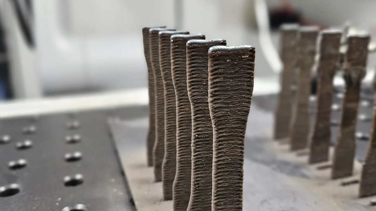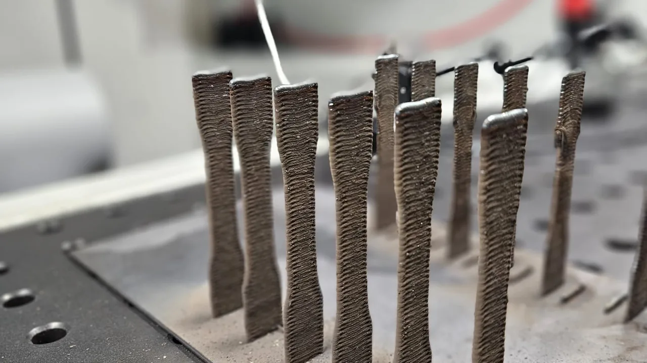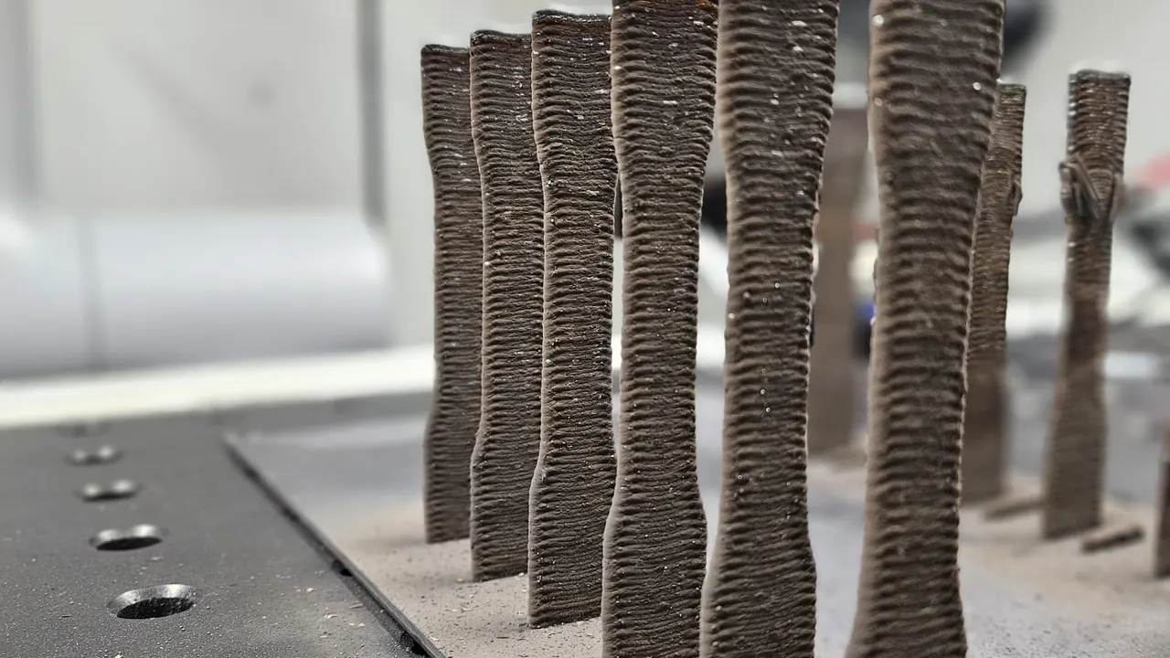
Excess weld metal (ISO 6520-1 reference 502) is reinforcement built up above the joint face. Unlike a volumetric or planar discontinuity, it is not a gap in the weld — it is more metal than the joint needed, sitting on the surface where it can be measured directly.
That makes it easy to under-rate. On a statically loaded structure a proud cap often reads as harmless: more metal, more strength. This article covers why that reading does not hold everywhere, what drives the excess, and what a process record can add before the cap is finished. It does not set acceptance limits or replace the inspection method a contract requires.
Key takeaways
- Excess weld metal is a parameter problem: travel speed, current and wire feed speed relative to each other.
- On cyclically loaded work, a steep transition from cap to parent surface behaves like a stress concentration, not like extra strength.
- The usual correction — grinding or gouging a proud cap flush — carries its own risk if it removes sound parent material.
- Visual inspection is the primary detection route because the imperfection is a measurable surface profile, not a hidden discontinuity.
- A per-pass process record can flag a drifting parameter before the final cap is ground and re-qualified.
What drives the excess
The defects reference entry for excess weld metal sets out the cause matrix in full; in short, it comes down to how much filler is deposited per unit length or time relative to what the joint geometry needs:
- Travel speed slower than the qualified procedure deposits more filler per unit length than the joint needs, and the excess sits on top rather than tying into the sidewalls.
- Wire feed speed or current above the qualified range delivers more filler per unit time than the arc can spread into a flat profile.
- Repeated passes with no dressing between them each add height without removing the crown left by the previous pass, particularly on a wide multi-pass groove.
- A joint gap or bevel angle wider than designed needs more filler to fill flush, which leaves more metal above the surface than a narrower joint would.
None of these are material defects in the metallurgical sense — they are a procedure or fit-up drifting from what was qualified.
Why the correction is the real risk
An aggressive grind or gouging pass used to bring a proud cap flush can cut into sound parent material, and the re-weld needed to repair that gouge adds a heat cycle the original joint never required. The corrective action can end up doing more metallurgical harm than the excess metal itself.
On cyclically loaded work the calculus is different again: a steep transition from the reinforcement down to the parent surface behaves like a shallow notch — a stress concentration — rather than like extra load-bearing metal. This is why fatigue-governed codes profile the cap shape, not only its height above the plate.
[Assumption / ipotesi] Whether a given joint is treated as statically or cyclically loaded, and which acceptance criterion therefore applies, is a design and code decision. Confirm it against the governing specification before setting a disposition rule.
What a process record can show
Excess weld metal does not require a hidden-defect detection method — it is a surface profile, directly measurable once the pass is complete. What a continuous process record adds is earlier warning, before the cap is finished and has to be ground back:
- Travel speed logged against the qualified procedure, rather than judged by eye once the run is finished — travel speed is the parameter most likely to drift on manual work as a welder chases a full-looking bead.
- Wire feed speed and current logged per pass against the qualified window, not the panel dial setting.
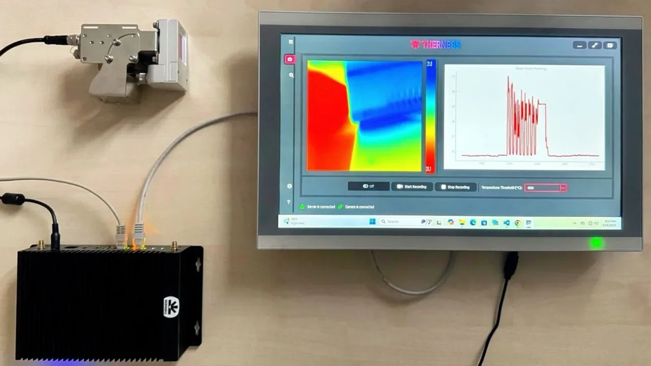
- Thermal footprint per pass. A growing bead width and height changes the cooling footprint pass to pass; a drifting thermal signature can flag the parameter before the cap is finished, in support of — not instead of — the profile measurement itself. The welding monitoring system overview and HeatCam IR-S describe how thermal and process channels are combined into a per-weld record; HeatCore AI is the analysis layer.
This is a supporting signal, not the detection method. The defects reference entry is explicit that visual testing to ISO 17637, with weld profile gauges, is the primary route, and that radiographic and ultrasonic methods are of limited use here because they target volumetric or planar discontinuities, not a shape imperfection.
[Assumption / ipotesi] The correlation between cooling-footprint drift and cap growth needs to be validated on the target joint geometry and process before it is trusted as an early-warning signal; treat it as a candidate for pilot validation, not a proven detector.
Where acceptance is set
The permitted reinforcement profile depends on the selected quality level and the governing code — ISO 5817 for steel, ISO 10042 for aluminium alloys, or a code-specific criterion such as AWS D1.1 for structural steel or API 1104 for pipeline girth welds. This article does not reproduce those limits; check the current edition and the applicable clause for the contract in question. Related surface-profile defects are covered in the undercut guide and the porosity guide.
Building the evidence pack
A defensible record for a joint at risk of excess weld metal links the qualified WPS parameters, the per-pass log of travel speed, current and wire feed speed against that procedure, the thermal footprint where available, and the final visual profile measurement against the applicable standard. The every-weld coverage guide explains how to reconcile monitoring records against the full population of welds so a gap is caught rather than assumed clean.
The value of that record is catching a drifting parameter early — before a full pass has to be ground back and re-qualified — not replacing the visual inspection the imperfection is designed to be caught by.
Sources
- Therness excess weld metal reference (ISO 6520-1, code 502) — cause matrix, detection methods and acceptance pointers.
- Undercut in welding: causes, prevention — related surface-profile defect.
- Therness welding monitoring system — system workflow and sensing context.
- Therness HeatCore AI — monitoring and analysis layer context.
- ISO 6520-1 — classification of geometric imperfections in fusion-welded metallic materials; verify the applicable edition.
- ISO 5817 — quality-level context for weld imperfections in steel, nickel and titanium alloys; check applicability and the current edition. ISO 10042 covers the equivalent levels for aluminium.
Catch a drifting cap before it needs grinding back
Therness can help define which travel-speed, current and thermal parameters to log per pass, so a drift is flagged before the final visual check.
Discuss your processTherness solution: Welding monitoring system — Every weld inspected in the cycle, with defect flags and the ISO 3834 / ISO 17635 evidence kept per weld.