Inline weld inspection vs manual visual inspection is one of the highest-stakes decisions in production welding quality planning. Choose wrong and you either overspend on capital equipment that adds no value at low volume, or you accept defect escape rates that drive rework costs across your entire line. The right answer depends on volume, joint geometry, code requirements, and the actual cost of a defect reaching downstream — not on technology preference or vendor positioning.
This guide compares both methods across cost per weld, detection capability, throughput impact, and failure modes, and provides a structured decision framework to help quality engineers and plant managers choose the right inspection architecture for their specific production context.
Key takeaways
- Manual visual testing (VT) per EN ISO 17637 detects surface discontinuities only, requires certified inspector time per weld, and operates as a serial constraint on production flow.
- Inline inspection provides 100% coverage with zero added cycle time, captures subsurface thermal signatures invisible to VT, and enables intervention before a defect fully forms.
- At high volume (500+ welds/week on repeatable geometry), inline inspection ROI break-even is typically 6-18 months. Below 50 welds/week on varying geometry, manual VT is more cost-effective.
- Common inline failure modes — false-positive drift, fixture creep, grade-swap model mismatch — are preventable with structured commissioning and calibration protocols.
- EN ISO 3834-2 and sector codes (ASME Section IX, EN 15085) may require certified inspector hold-point witness regardless of inline system capability.
- The decision is not inline OR manual — it is inline PLUS manual for code hold points, versus manual-only for low-volume or high-complexity production.
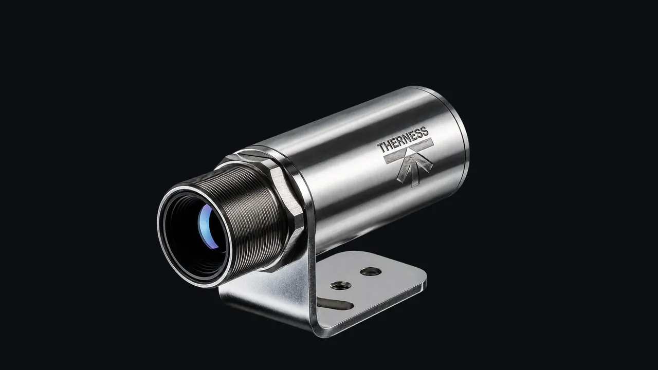
- A welding inspection camera integrated at the torch position captures real-time data without post-weld delay, forming the sensor backbone of any inline inspection architecture.
Table of Contents
- What Manual Visual Inspection Requires (EN ISO 17637)
- What Inline Weld Inspection Delivers
- Cost Comparison: Per-Weld Economics
- Speed and Throughput: Where Each Method Wins
- Detection Reliability and Capability
- Common Failure Modes and How to Fix Them
- Decision Framework: Which to Choose
- Frequently Asked Questions
What Manual Visual Inspection Requires (EN ISO 17637)
Manual visual testing of fusion welds is governed by EN ISO 17637:2016, the international standard that defines minimum conditions for visual examination of welds in metallic materials. It specifies lighting (500 lux minimum at the weld surface, 50 lux ambient), viewing angle (minimum 30 degrees), viewing distance (maximum 600 mm), and inspector qualification under EN ISO 9712.
What a Qualified VT Inspection Involves
A certified VT inspector examines the weld bead visually, uses calibrated gauges to verify dimensional conformance, and classifies discontinuities against the applicable acceptance standard — typically ISO 5817 weld acceptance criteria for structural and general welding applications, or ASME B31.3 for process piping.
Standard inspection sequence per weld under EN ISO 17637:
- Surface preparation check — weld clear of spatter, flux residue, or contamination blocking view
- Bead geometry assessment — convexity, concavity, width consistency across weld length
- Dimensional measurement — throat size and leg length for fillet welds, cap width for butt welds
- Surface discontinuity classification — cracks, surface porosity, undercut, overlap, excessive convexity
- Acceptance/rejection decision against applicable quality level (ISO 5817 level B, C, or D)
- Documentation of findings with weld ID and inspector signature
The TWI — The Welding Institute provides comprehensive reference data on VT technique requirements and inspector proficiency benchmarks.
Capability Limits
Manual VT detects surface discontinuities only. Subsurface lack of fusion, incomplete penetration, and internal porosity are invisible to visual inspection regardless of inspector skill level. Detecting those defects requires volumetric NDT methods — radiographic testing (RT) or ultrasonic testing (UT) per EN ISO 17636 or EN ISO 17640.
Inspector performance also varies with fatigue, lighting quality, and experience. Research by the International Institute of Welding (IIW) has documented inter-inspector variability on borderline discontinuity classifications of 15-30% on identical weld samples. This is not a failure of the method — it reflects the fundamental limit of human perception applied to defined acceptance boundaries.
Where Manual VT is the Right Choice
- Low volume, high geometric complexity: variable joint types, 3D weld paths, or access-constrained configurations where sensor placement is impractical
- Regulatory hold-point witness: EN ISO 3834-2 and ASME Section IX require certified inspector witness at defined hold points — an inline system cannot substitute
- First-off and qualification welds: new procedure qualifications per AWS D1.1 or EN ISO 15614-1 require documented human VT
- R&D and prototype work: novel geometries and material combinations where sensor calibration data does not yet exist
What Inline Weld Inspection Delivers
Inline inspection integrates measurement directly into the welding cell, capturing data from every weld pass in real time — during or immediately after welding, before the part is released from the fixture. Sensor types differ by monitoring objective.
Thermal / infrared sensors capture weld pool temperature distribution and heat-affected zone extent during and after welding. They detect heat input anomalies that correlate with lack of fusion, excessive HAZ, root penetration defects, and improper preheat. A real-time weld monitoring system based on infrared imaging provides quantitative thermal data at every millimetre of weld length.
Vision-based sensors capture bead geometry, surface profile, and weld pool shape during arc-on time. They detect bead width deviation, surface porosity, crown height anomaly, start/stop quality, and undercut on the finished surface.
Arc signal monitors capture welding current, voltage, and wire feed rate at millisecond resolution. They detect parameter drift, short-circuit events, and arc instability that precede visible defect formation — flagging the process before the defect is deposited.
The Therness HeatCam IR-C and PoolDrop cameras are designed for inline integration in MIG/MAG and TIG production cells, providing thermal and weld pool data streams within the production cycle.
The Core Advantage: Intervention Before Defect Formation
Manual VT occurs after welding is complete and the part has cooled. Inline monitoring captures process data as each millimetre of weld is deposited. A heat input excursion at weld position 130 mm triggers an alert at position 130 mm — not when the part arrives at the inspection station 40 minutes later. This is the fundamental economic difference: inline inspection shifts defect control from detection-after-loss to prevention-within-cycle.
100% Coverage Without Cycle Time Cost
Inline inspection runs in parallel with welding. The inspection result is available as the arc extinguishes. No additional cycle time is added. Manual VT adds 2-8 minutes per weld at EN ISO 17637 dwell requirements, plus queue time in high-volume environments, and typically achieves 10-30% sampling coverage when full 100% VT would be cost-prohibitive.
Cost Comparison: Per-Weld Economics
| Cost Category | Manual VT | Inline Inspection |
|---|---|---|
| Per-weld inspection cost (labour) | €3-15 per weld (inspector rate × dwell time) | <€0.02 after commissioning (amortisation + power) |
| Capital cost | Low (gauges, lighting: €2k-10k) | €20k-150k (sensor, software, integration) |
| Integration / commissioning | Days (procedure, training) | 4-12 weeks (mechanical fit, software validation) |
| Coverage rate at high volume | 10-30% sampling (unless staffed for 100%) | 100% every weld |
| Defect escape cost | High at sampling rates below 100% | Low (early detection, 100% coverage) |
| Documentation | Manual entry, inspector signature | Automated per-weld records, timestamp, weld ID |
| Regulatory hold-point cost | Included (inspector = compliance) | Additional (inspector still needed at hold points) |
Break-even illustration: at 200 welds/day at €6 average VT cost (inspector + overhead), inspection cost is €1,200/day. A €60k inline system with 6-week commissioning breaks even in approximately 50 production days — before accounting for rework cost reduction from 100% coverage replacing 20% sampling.
The NIST Engineering Laboratory and ASME codes and standards provide framework references for manufacturing cost models and quality cost quantification applicable to this calculation.
Speed and Throughput: Where Each Method Wins
Manual VT as a Serial Constraint
Manual VT is a sequential gate. Parts queue for inspection; inspectors work through the queue; rework loops run back to the welding station. In a typical structural steel or automotive subframe line, inspection scheduling accounts for 15-25% of total part cycle time. That overhead exists regardless of defect rate.
The throughput ceiling for manual VT is inspector headcount. For a three-shift line producing 1,500 welds per day, full EN ISO 17637 VT coverage requires approximately 4-6 dedicated inspectors per shift. Every inspector absence creates a backlog.
Inline Inspection Throughput Characteristics
Inline inspection adds zero cycle time to the welding sequence. Throughput scales with the welding line — adding a second robotic station adds one sensor, not one inspector. Documentation is automated; no end-of-shift paperwork backlog exists.
The throughput advantage is most visible in high-volume, high-mix environments where manual VT would require either significant inspector headcount or acceptance of low sampling rates.
Where Manual VT Is Faster in Practice
Manual VT has a speed advantage in rework assessment and repair approval. Determining the nature, extent, and preferred repair method for a discovered defect requires contextual judgment that no current inline system replicates. Experienced inspectors assess the weld, specify the repair, and approve the rework result in a single site visit. Inline systems generate alerts; humans still make repair disposition decisions.
Detection Reliability and Capability
Defect Coverage by Method
| Defect Type | Thermal Inline | Arc-Signal Inline | Manual VT (EN ISO 17637) |
|---|---|---|---|
| Surface porosity | Partial (thermal surface effect) | Indirect (arc instability signature) | Yes — visible pore exits |
| Subsurface porosity | No | No | No |
| Lack of fusion | Yes (cold zone in thermal map) | Yes (short-circuit signature) | No (internal defect) |
| Undercut | Vision-based only | No | Yes |
| Bead geometry deviation | Yes (thermal + vision) | Indirect | Yes |
| Incomplete root penetration | Yes (root-side thermal) | Yes (parameter excursion) | No |
| HAZ overheating | Yes (direct measurement) | Yes (heat input excursion) | No |
| Crater cracks | Partial (thermal + vision) | Partial | Yes |
Reliability of Human Inspection
The European Welding Federation (EWF) has published data showing inter-inspector variability on borderline discontinuity classifications of 15-30% on identical samples under controlled conditions. The IIW has documented false-negative rates for manual VT on complex fillet welds of 8-22% depending on inspector experience and fatigue state. Neither figure represents inspector incompetence — they reflect the limits of human sensory resolution applied to defined numerical acceptance thresholds.
Inline systems produce consistent results independent of fatigue, shift time, or operator attention. A calibrated threshold at commissioning produces the same classification at midnight on day 180 as it did at 08:00 on day 1. The trade-off is that the system does not improve with production experience the way a skilled inspector does — and it fails in novel scenarios where its calibration data does not apply.
Common Failure Modes and How to Fix Them
Inline Inspection Failure Modes
False-positive rate drift after consumable changeover Threshold calibrated on one wire specification; new batch shifts arc signature. Fix: re-calibrate threshold on 50 production welds after every consumable batch change. Include in changeover SOP.
Fixture creep (sensor field-of-view shift) Vibration from robotic motion loosens mounting hardware over weeks. Fix: add weekly field-of-view verification step (target board check, centroid position vs reference). Tolerance: 2 mm before re-tighten and recalibrate.
Training data mismatch on material grade swap AI classifier trained on S235 underperforms on S355 or duplex stainless. Fix: build grade-specific model variants with minimum 200 validated training welds per grade. Document grade scope in the system validation report and never re-use a model across grades without re-validation.
Weld ID dropout (traceability gap) Barcode scanner misread or robot PLC fails to push weld ID to the inspection system. Fix: implement hard-coded fallback ID (timestamp + cell ID) and flag the record for manual review. Never log a weld record with null weld ID in a traceability-required system.
Manual VT Failure Modes
Insufficient lighting at the inspection point Portable lamp degraded, reflective glare on root pass, or inspector using inadequate light source. Fix: calibrate lux meter quarterly; add a 500 lux verification check at weld surface as a mandatory pre-inspection step.
Missed borderline undercut Visual depth judgment on 0.5 mm undercut (ISO 5817 Level C limit) is below reliable human sensory resolution. Fix: require calibrated undercut depth gauge for every weld where undercut is suspected. Never allow naked-eye depth assessment for an acceptance decision.
Documentation completed from memory Inspector completes a batch and fills records retrospectively. Fix: require per-weld immediate entry; audit timestamps against weld completion records. Discrepancy >15 minutes triggers documentation review.
Decision Framework: Which to Choose
Step 1 — Volume and Repeatability Screen
| Weekly weld count | Joint geometry | Recommended inspection approach |
|---|---|---|
| Above 500 welds/week | Identical joint type | Inline inspection primary — ROI typically under 12 months |
| 100-500 welds/week | Mostly repeatable | Hybrid: inline primary, manual VT for hold points |
| Below 100 welds/week | Variable geometry | Manual VT |
| Any volume | R&D, first-off, custom | Manual VT + volumetric NDT |
Step 2 — Code Requirement Check
Review your applicable code before deciding. Key requirements:
- EN ISO 3834-2: requires documented in-process controls — satisfiable by either inline monitoring with a validated procedure or manual VT under a documented inspection plan
- ASME Section IX / EN 13480: hold points require certified inspector witness; inline system satisfies monitoring but not witness requirement
- EN 15085 (railway CL1): requires 100% volumetric NDT on CL1 joints; inline thermal monitoring is complementary, not substitutive for RT/UT
Check the American Welding Society (AWS) and CEN standards catalogue for current code revision requirements applicable to your product category.
Step 3 — Cost-Per-Escaped-Defect Calculation
Quantify the decision using four variables:
R— average rework cost per escaped defect (materials, labour, downtime)E%— current defect escape rate at your VT sampling levelV— weekly production volume (welds)C— inspector cost per weld (labour rate × dwell time)
Manual VT annual cost = V × 52 × C + V × 52 × E% × R
Inline system annual cost = (CAPEX / 5-year amortisation) + (commissioning cost / 3 years) + residual manual VT for hold points
If inline system annual cost is below manual VT annual cost at your volume and defect rate, the investment is justified. The ASM International quality cost reference data and NIST manufacturing benchmarks provide industry baseline values for E% and R by production sector.
Decision Checklist
- Weekly weld volume and joint repeatability assessed
- Code-required hold points and witness requirements identified from applicable standard
- Cost-per-escaped-defect calculated with real rework data (not estimates)
- Sensor mounting feasibility confirmed on production fixture
- Integration scope defined (PLC interface, weld ID input, network, data storage)
- Commissioning validation plan drafted — minimum 200 parallel inspection welds
- Downtime fallback procedure documented (default to full manual VT during system outage)
For a deeper evaluation of weld defect detection software that integrates with inline hardware — including AI detection capabilities, integration architecture, and the parallel validation protocol — see the full buyer’s guide.
Hybrid architecture is the most common outcome for mid-volume production: inline inspection as the primary 100% coverage method for routine welds, manual VT reserved for code-required hold-point witness and complex joint types where sensor coverage is impractical. Neither method needs to handle everything alone.
Where the inspection design needs controlled excitation rather than passive monitoring, an excitation-based thermographic setup can be assessed alongside the inline options.
Frequently Asked Questions
What is inline weld inspection?
Inline weld inspection is automated quality monitoring performed in real time during or immediately after welding, integrated into the production cell. Sensors — typically thermal, vision, or arc-signal-based — capture weld data for every pass, providing 100% coverage without interrupting production throughput.
How does inline weld inspection compare to manual visual inspection for cost?
Manual VT cost is dominated by inspector labour at EN ISO 17637 dwell times (typically 2-8 minutes per weld), rework from late defect detection, and scheduling overhead. Inline inspection trades a capital investment for near-zero per-weld cost after commissioning. ROI break-even ranges from 6 to 18 months depending on volume, defect rate, and rework cost per unit.
Can inline weld inspection replace manual visual inspection entirely?
For high-volume, repeatable weld geometries on known materials, inline systems can replace routine manual VT as the primary in-process check. However, codes including EN ISO 3834-2, ASME Section IX, and sector standards may still require certified inspector witness at defined hold points. Inline inspection replaces the routine check, not the code-required witness.
What defects can inline weld inspection detect that manual VT misses?
Thermal-based inline systems detect heat input anomalies that correlate with lack of fusion, incomplete penetration, and HAZ overheating — invisible on a cooled weld surface. They also flag parameter drift before a visually detectable defect forms, enabling correction before the defect fully develops, which manual VT cannot do.
How does manual visual inspection comply with EN ISO 17637?
EN ISO 17637 specifies 500 lux minimum lighting, 600 mm maximum viewing distance, and 30 degree minimum viewing angle. Inspector qualification under EN ISO 9712 is required. Calibrated gauges must be used wherever dimensional acceptance criteria apply. These requirements create a documentable, auditable inspection process — not informal eyeballing.
What is the false-positive rate for inline weld inspection systems?
Production-validated inline systems achieve false-positive rates of 2-8% in steady-state operation. Rates increase after consumable changeovers, material grade swaps, or fixture drift. Commissioning calibration on representative production welds is essential to establish the baseline rate before production start.
What standards govern automated inline weld inspection?
Applicable frameworks include ISO 3834-2 for quality requirements in fusion welding processes, EN 15085 for railway applications, AWS D1.1 for structural steel, and ASME quality codes for pressure equipment. Validation against known defect samples before production use is required regardless of the applicable code.
How do I choose between inline and manual inspection?
Above 500 identical welds per week on the same geometry, inline inspection economics are almost always favourable. Below 50 welds per week on variable geometry, manual VT is more cost-effective. Between those thresholds, calculate cost-per-defect-missed using real rework cost data, inspection cycle time, and actual defect escape rate — the decision framework above provides the full calculation structure.
Evaluate Inline Weld Inspection for Your Production Line
Therness builds thermal and vision-based inline inspection systems for MIG/MAG and TIG production cells. Talk to our engineering team about sensor integration, commissioning scope, and validation protocol for your specific weld geometry and volume.
Contact our teamTherness solution: Welding monitoring system — Every weld inspected in the cycle, with defect flags and the ISO 3834 / ISO 17635 evidence kept per weld.
Frequently Asked Questions
What is inline weld inspection?
Inline weld inspection is automated quality monitoring performed in real time during or immediately after welding, integrated into the production cell. Sensors — thermal, vision, or arc-signal-based — capture weld data for every pass, eliminating post-weld sampling delays and providing 100% coverage without interrupting production throughput.
How does inline weld inspection compare to manual visual inspection for cost?
Manual VT cost is dominated by inspector labour (2-8 minutes per weld at EN ISO 17637 dwell times), rework from late defect detection, and scheduling overhead. Inline inspection trades a capital investment and integration effort for near-zero per-weld inspection cost after commissioning. ROI break-even typically ranges from 6 to 18 months depending on volume, defect rate, and rework cost.
Can inline weld inspection replace manual visual inspection entirely?
For high-volume, repeatable geometries on known materials, inline systems can replace routine manual VT as the primary in-process check. However, codes including EN ISO 3834-2 and ASME Section IX may still require certified inspector witness at defined hold points. Inline inspection replaces the routine check, not the code-required witness.
What defects can inline weld inspection detect that manual VT misses?
Thermal-based inline systems detect heat input anomalies that correlate with lack of fusion, incomplete penetration, and HAZ overheating — all invisible to the naked eye on a cooled weld surface. They also flag parameter drift before a visually detectable defect forms, enabling correction before the defect exists, which manual VT cannot do.
How does manual visual inspection comply with EN ISO 17637?
EN ISO 17637 specifies minimum lighting (500 lux at the weld surface), viewing angle (minimum 30 degrees), viewing distance (maximum 600 mm), and inspector qualification under EN ISO 9712. Calibrated gauges must be used wherever dimensional acceptance criteria apply. These requirements make VT a defined, documentable process with auditable evidence.
What is the false-positive rate for inline weld inspection systems?
Production-validated inline systems achieve false-positive rates of 2-8% in steady-state operation. Rates increase during consumable changeovers, material grade swaps, or fixture drift. Threshold calibration on representative production welds at commissioning is essential to establish the baseline rate before production start.
What standards govern automated inline weld inspection?
No single standard directly governs inline monitoring systems. Applicable frameworks include ISO 3834-2 (quality requirements for fusion welding processes, including monitoring and testing), EN 15085 for railway applications, and sector codes such as AWS D1.1. Validation against known defect samples before production use is required regardless of the applicable code.
How do I choose between inline and manual inspection for my production line?
Above 500 identical welds per week on the same joint geometry, inline inspection economics are almost always favourable. Below 50 welds per week on varying geometry, manual VT is typically more cost-effective. Between those thresholds, calculate cost-per-defect-missed using your rework cost, inspection cycle time, and defect escape rate.