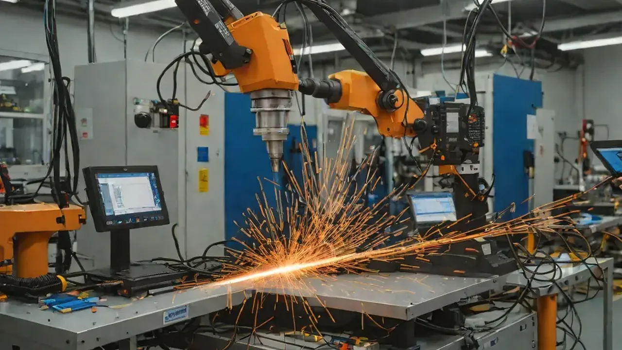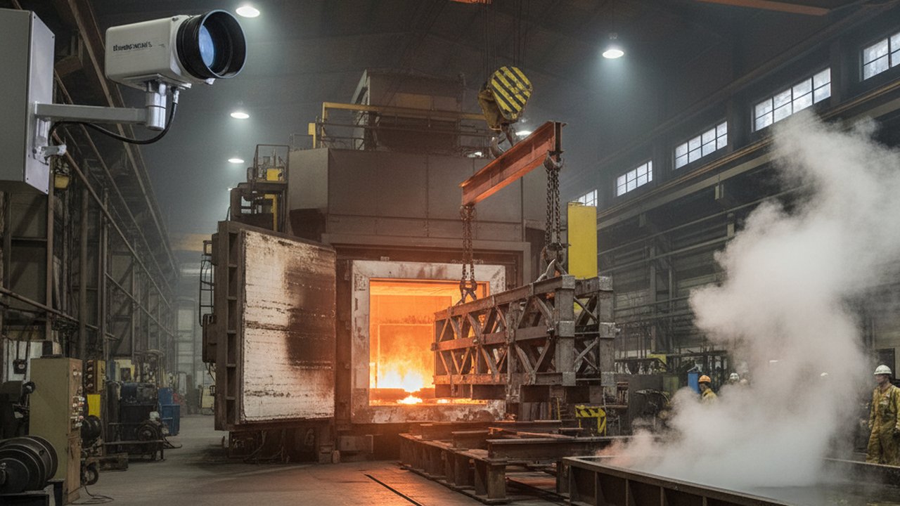
Weld overlay cladding quality monitoring has become essential for industries deploying corrosion-resistant overlays on pressure vessels, pipe flanges, and critical components. As oil & gas, petrochemical, and power generation sectors face increasing demands for equipment longevity, real-time thermal imaging offers a transformative approach to controlling dilution rates, detecting defects, and ensuring overlay integrity during deposition.
Traditional inspection methods—visual testing, ultrasonic testing, and destructive sampling—remain vital but occur post-weld. Thermal imaging enables in-process quality control, catching deviations before they become costly repairs or field failures.
Understanding Weld Overlay Cladding
Weld overlay cladding deposits a corrosion-resistant or wear-resistant alloy layer onto a base metal substrate. Common applications include:
- Pressure vessel internals in refineries and chemical plants
- Pipe flanges and valve bodies exposed to aggressive media
- Boiler tubes requiring erosion and corrosion protection
- Offshore subsea components facing seawater and H₂S environments
- Nuclear component surfaces demanding precise metallurgical control
The overlay material—typically nickel alloys (Alloy 625, Alloy 825), stainless steels, or cobalt-based hardfacing alloys—must bond metallurgically with the base metal while maintaining its corrosion resistance properties.
The Critical Role of Dilution Rate
Dilution rate defines the percentage of base metal that mixes into the overlay during deposition. Higher dilution means more base metal content in the cladding, potentially compromising corrosion resistance.
Research from TWI shows that Alloy 625 overlays maintain acceptable corrosion resistance until dilution exceeds approximately 36% iron content. Below this threshold, pitting resistance remains excellent. Above it, corrosion performance degrades significantly.
Different welding processes produce varying dilution characteristics:
| Process | Typical Dilution Range |
|---|---|
| TIG (GTAW) | Less than 10% to 70% (high scatter) |
| MIG (GMAW) | Less than 40% (more consistent) |
| Submerged Arc | 25-40% |
| Electro-Slag | 10-20% |
| Laser Cladding | Less than 5% |
Controlling dilution within specified limits is paramount. Thermal imaging provides the real-time feedback needed to maintain optimal heat input and travel speed—the primary factors governing dilution.
Quality Challenges in Overlay Deposition
Common Defect Types
Weld overlay cladding faces specific defect categories that differ from conventional butt welds:
Porosity results from gas entrapment during solidification. In overlays, porosity can propagate through multiple layers, creating leak paths. Causes include inadequate shielding gas coverage, contaminated filler wire, or excessive arc voltage.
Lack of fusion at the interface between overlay and base metal creates weak bonds susceptible to spalling under thermal cycling. Low heat input, excessive travel speed, or surface contamination are typical causes.
Cracking manifests in several forms:
- Solidification cracks (hot cracks) occur during cooling from high impurity content or poor heat flow
- Delayed hydrogen cracks (cold cracks) develop hours or days after welding from residual stress and hydrogen diffusion
- Dissimilar metal interface cracks result from thermal expansion mismatch between overlay and substrate
Excessive dilution—while not a discrete defect—represents a metallurgical condition where the overlay composition shifts outside specification, reducing corrosion resistance.
Current Inspection Standards
Industry standards mandate specific inspection requirements for weld overlay qualification and production:
ISO 15614-7:2016 specifies welding procedure qualification tests for overlay welding. It mandates 100% visual testing per ISO 17637 and 100% ultrasonic testing per ISO 17640 for bond integrity verification.
ASME Section IX governs procedure qualification for corrosion-resistant overlays in ASME-code applications. It requires liquid penetrant testing per Section V, Article 6, plus bend tests and chemical analysis at specified overlay depths.
These standards address post-weld verification. In-process monitoring remains largely unstandardized, creating an opportunity for thermal imaging technology.
Thermal Imaging for Real-Time Overlay Monitoring
How Thermal Imaging Detects Quality Issues
Infrared cameras capture the thermal radiation emitted by the weld pool, heat-affected zone, and cooling overlay. Temperature patterns reveal process dynamics invisible to visual inspection:
Temperature gradient analysis shows heat distribution across the overlay width. Uneven gradients indicate arc instability or inconsistent travel speed—precursors to dilution variation.
Cooling rate monitoring correlates directly with microstructural outcomes. Rapid cooling can produce brittle phases in certain alloy systems; excessive cooling rates may prevent proper carbide dissolution.
Hot spot detection identifies localized overheating from arc concentration, indicating potential for excessive penetration and dilution.
Process deviation capture records thermal signatures when parameters drift from qualified ranges, enabling immediate corrective action.
Implementation Architecture
A complete thermal monitoring system for overlay cladding includes:
- Infrared camera positioned to view the weld pool and trailing overlay
- Protection system with air purge and optical filtering to survive spatter and fumes
- Real-time processing unit converting raw thermal data to quality metrics
- Integration interface connecting to welding power source and motion system
- Recording and traceability storing thermal data for quality records
The camera must capture sufficient frame rates (typically 30-60 fps minimum) to track the moving weld pool. Spatial resolution determines the minimum detectable defect size—a 640×480 array provides adequate detail for most overlay applications. Purpose-built analytics units such as HeatCore AI fold these temperature-gradient and cooling-rate readings into automated per-pass quality metrics.

Dilution Rate Control Through Thermal Feedback
Thermal Correlates of Dilution
Dilution rate correlates with several measurable thermal parameters:
Peak temperature at the fusion line indicates base metal melting extent. Higher peak temperatures suggest greater penetration and potential dilution increase.
Width of the high-temperature zone reflects the heat input distribution. Narrow zones with high peak temperatures indicate concentrated heat that may cause localized excessive dilution.
Cooling rate at the solidification front influences the metallurgical structure and can indicate whether proper fusion occurred.
Process Control Strategies
Thermal imaging enables closed-loop control of overlay parameters as part of a wider real-time cladding monitoring setup:
Heat input regulation adjusts welding current based on measured temperature profiles. When thermal imaging detects excessive heat input, the system reduces current to maintain target dilution.
Travel speed optimization matches deposition rate to thermal conditions. Slower travel increases heat input per unit length; faster travel reduces it. Thermal feedback ensures optimal speed for the required overlay thickness.
Weave pattern adjustment in oscillating overlays controls heat distribution across the bead width. Thermal imaging reveals whether the weave produces uniform heating or hot spots.
Field implementations have demonstrated dilution control within ±2% when thermal feedback drives process adjustments—a significant improvement over open-loop deposition.
Defect Detection Capabilities
Porosity and Gas Entrapment
Thermal imaging detects porosity through temperature anomalies in the solidifying overlay. Gas bubbles create localized cooling variations as they interrupt heat conduction. The signature appears as cold spots in the otherwise smooth thermal gradient.
Detection limits depend on camera resolution and frame rate. Porosity larger than2mm diameter is reliably detectable during deposition; smaller pores may require post-weld NDT confirmation.
Lack of Fusion
Bond line integrity shows clearly in thermal recordings. Areas lacking proper fusion exhibit abnormal cooling patterns—the interface acts as a thermal barrier, creating distinct temperature steps across the unfused region.
The advantage over ultrasonic testing: detection occurs during deposition when repair is immediate and straightforward, rather than after the overlay is complete.
Cracking Initiation
Solidification cracks produce characteristic thermal signatures as they open. The crack surface radiates more intensely than surrounding material, appearing as a bright line in thermal recordings.
For delayed hydrogen cracking, thermal imaging cannot directly predict future defects. However, it can identify conditions that promote cracking risk—rapid cooling, excessive hardness zones, or incomplete hydrogen diffusion windows.
Integration with Quality Management Systems
Traceability Requirements
Industries requiring weld overlay documentation must maintain comprehensive records. Thermal imaging data augments traditional quality records:
- Thermal recording files linked to specific overlay passes
- Process parameter logs showing thermal metrics alongside electrical parameters
- Deviation reports documenting excursions from thermal limits
- Corrective action records for process adjustments made during deposition
This data aligns with ISO 3834 quality requirements for fusion welding of metallic materials, providing objective evidence of process control.
Complementary NDT Approach
Thermal monitoring does not replace traditional NDT—it complements it. The optimal inspection strategy combines:
- In-process thermal monitoring for real-time control
- Visual inspection for surface condition verification
- Ultrasonic testing for final bond integrity confirmation
- Destructive testing for procedure qualification and statistical sampling
This layered approach maximizes defect detection probability while minimizing overall inspection costs.
ROI Considerations for Overlay Monitoring
Cost of Overlay Defects
Undetected overlay defects carry significant downstream costs:
- Field failures in pressure vessels can cause plant shutdowns costing $100,000+ per day
- Repair welds require excavation, re-qualification testing, and extended schedule impact
- Warranty claims from overlay failures damage customer relationships and reputation
- Regulatory penalties for equipment operating outside code requirements
For critical applications like offshore platforms or nuclear components, a single undetected defect can exceed $1M in total cost.
Investment Payback Analysis
Thermal monitoring systems for overlay cladding typically show payback periods of 12-18 months for high-value applications. Key value drivers:
- Reduced repair rates from in-process defect detection
- Higher deposition productivity through optimized parameters
- Lower NDT costs from targeted inspection of flagged areas
- Extended equipment life from consistently qualified overlays
For facilities performing frequent overlay work, the combination of quality improvement and productivity gain justifies the monitoring investment.
Conclusion
Weld overlay cladding quality monitoring through thermal imaging represents a significant advancement for industries relying on corrosion-resistant overlay performance. By controlling dilution rates, detecting defects in real-time, and providing objective quality documentation, thermal monitoring transforms overlay welding from a process-dependent craft to a data-driven operation.
As equipment service environments become more demanding and regulatory scrutiny intensifies, the value of in-process quality assurance continues to grow. Organizations investing in thermal monitoring capabilities position themselves for higher quality outcomes, lower total costs, and enhanced competitive positioning in demanding markets.
For facilities seeking to implement overlay quality monitoring, partnering with experienced thermal imaging providers—and reviewing our product range—ensures proper system design, calibration, and integration with existing quality management processes.
Related Articles:
- ISO 15614 Welding Procedure Qualification Digital Workflow
- Pressure Vessel Welding Quality Monitoring ISO 3834 PED
- Submerged Arc Welding Quality Monitoring Thermal Imaging
- Heat Input Cooling Rate T85 Microstructure Weld Quality
- Watch: Cladding process monitoring with HeatCore AI (video demo)
Therness solution: Welding camera — Thermal and high-speed imaging that watches the arc, the pool and the cooling seam while the weld is made.