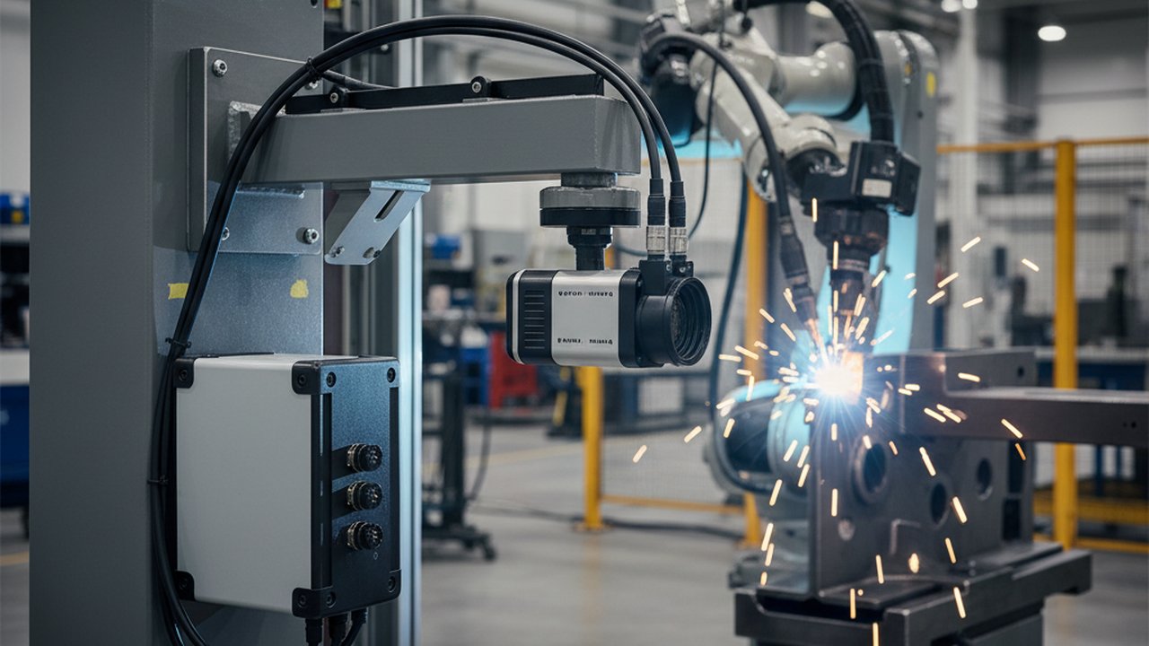
Infrared weld monitoring of interpass temperature closes one of the most persistent documentation gaps in multi-pass welding: the gap between what the procedure specifies — “maintain interpass temperature below 250 °C before each pass” — and what actually happened on the joint. Traditional spot pyrometers and contact thermocouples give a single reading at a single point, logged by hand. A LWIR thermal camera gives a full spatial temperature map of the heat-affected zone, continuously, automatically, and linked to the job record.
This guide explains the physics behind infrared interpass measurement, compares it to contact methods, walks through a step-by-step implementation procedure, addresses common failure modes, and shows how the resulting data satisfies ISO 3834-2 and EN 15085 traceability requirements.
Key Takeaways
- LWIR thermal cameras measure interpass temperature non-contact across the entire heat-affected zone simultaneously — not at a single point.
- Correct emissivity setting for the steel surface condition is the single largest source of measurement error; verify empirically before every new material or surface preparation.
- EN ISO 13916 permits infrared measurement devices for preheat and interpass temperature; the camera must be calibrated and the emissivity value must be documented in the measurement procedure.
- Full-field thermal monitoring catches hot spots between passes that spot pyrometers or single-point thermocouples miss entirely — particularly at weld start/stop locations and in thick-section joints.
- Per-job thermal logs satisfy ISO 3834-2 documentation requirements without manual data entry, eliminating the most common interpass record nonconformance in welding quality audits.
- Integration with weld sequence logic allows an automatic interpass hold: the system releases the arc only when every measured pixel in the joint zone is within the WPS temperature window.
- Emissivity error of 0.10 on oxidised steel introduces ±15–25 °C measurement bias at interpass ranges — well above the tolerance for most structural welding procedures.
Table of Contents
- Why Interpass Temperature Is a Critical Weld Quality Parameter
- Traditional Interpass Temperature Measurement Methods
- How LWIR Thermal Cameras Measure Interpass Temperature
- Measurement Accuracy: Thermal Camera vs Contact Methods
- Step-by-Step Implementation of Infrared Interpass Monitoring
- Common Failure Modes and Fixes
- Validation Procedure: Confirming Camera Accuracy Against Reference
- Standards Compliance: ISO 3834, EN 15085 and EN 1011
- FAQ
Why Interpass Temperature Is a Critical Weld Quality Parameter
Interpass temperature — the temperature of the base metal measured immediately before striking the next pass in a multi-run weld — directly controls the mechanical properties of the completed joint. Holding interpass temperature within the WPS-specified window prevents two distinct failure modes:
Too high: Extended time above the sensitisation or softening temperature coarsens grain structure, reduces notch toughness, and increases susceptibility to hot cracking in austenitic stainless and high-alloy steels. In quenched-and-tempered high-strength steels, excess heat input from multiple passes held at high interpass temperature permanently degrades yield strength.
Too low (in hydrogen-susceptible steels): Rapid cooling increases the martensite fraction in the heat-affected zone, trapping diffusible hydrogen and raising the risk of hydrogen-assisted cold cracking. Minimum interpass temperatures for high-strength steels are specified in AWS D1.1 and in ASME Section IX procedure qualifications, and are as important to enforce as the maximum limit.
In regulated sectors — rail vehicle structures covered by EN 15085, pressure vessels governed by EN 13445, or pipelines qualified under ASME B31.3 — these limits are WPS parameters, not guidance. Exceeding them invalidates procedure compliance for that joint.
In post-weld quality audits, missing or incomplete interpass temperature records are among the top three nonconformance findings in welding manufacturer audits. Manual thermocouple logs are routinely incomplete because production pressure discourages the pause required to measure and record every pass.
Traditional Interpass Temperature Measurement Methods
Contact Thermocouples
K-type or N-type thermocouples applied directly to the base metal surface give highly accurate readings — typically ±1–3 °C when calibrated. The practical problems are well known: the thermocouple must be held or fixed at the exact measurement point; it provides only a single-point value that may miss hot spots elsewhere in the joint; it must be removed before each pass; and the reading must be manually logged. Under production pressure with tight weld sequences, these steps are routinely skipped.
Infrared Spot Pyrometers
A spot pyrometer provides a non-contact reading at a single point. It is faster than a thermocouple and requires no physical contact, but it still covers only one location per measurement and depends on the operator aiming correctly and setting the right emissivity — which is rarely verified. Records remain manual.
Temperature-Indicating Crayons
Tempilstik crayons melt at a rated temperature, confirming only that a surface reached or exceeded a threshold. They cannot record the actual temperature reached, cannot detect transient overtemperature events, and cannot provide a per-pass log. They are used for minimum preheat verification, not for maximum interpass control in regulated welding.
How LWIR Thermal Cameras Measure Interpass Temperature
Long-wave infrared (LWIR) cameras operating in the 8–14 µm spectral band detect thermal emission from the steel surface and convert it into a radiometric temperature image. At interpass temperature ranges (50–350 °C), steel thermal emission falls within the LWIR band, making these cameras the appropriate technology for this application.
Each pixel in the camera produces an independent temperature measurement. A 320×240 LWIR camera measuring a 200 mm joint at 0.5 m working distance produces roughly 64,000 simultaneous temperature readings per frame — at frame rates typically between 25 and 100 Hz. This is the fundamental advantage over any single-point contact or non-contact method.
Full-Field Advantage
In a multi-pass butt weld, heat distributes unevenly along and across the joint. A thermocouple placed at the midpoint of the joint may read 215 °C while the weld toe at the start tab or stop location remains above 290 °C due to residual heat from the previous run — the result of arc dwell at sequence start/stop. A LWIR camera captures the entire weld zone in one frame, identifying the true hot spot location regardless of where the highest temperature actually occurs. See automatic cooling-time analysis between passes for how the system tracks this thermal decay frame by frame.
This full-field capability is especially valuable for:
- Thick-section joints where temperature gradients along the joint axis can exceed 60 °C over 300 mm of joint length.
- Robotic welding cells where no operator is present to direct a pyrometer.
- Automated multi-pass sequences where interpass intervals are programme-controlled and the system must confirm temperature compliance before the next arc fires.
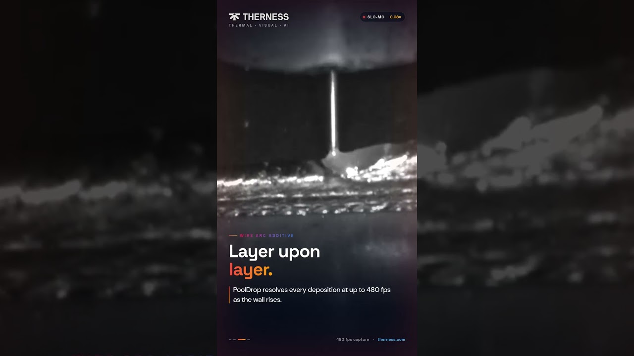
Therness HeatCam IR-S (fixed-mount, wide field of view for bench and robotic applications) and HeatCam IR-C (compact format for confined joint geometries) are designed specifically for interpass monitoring, with calibrated LWIR sensors and per-job data logging integrated into the measurement chain. Both models integrate with welding camera systems for combined arc and thermal monitoring when the application requires optical weld pool monitoring alongside interpass control.
A single LWIR camera frame replaces three to five thermocouple measurements per weld pass. In a twelve-pass heavy-section weld, that eliminates 36–60 manual measurement events — while simultaneously capturing more spatial information than any practical thermocouple array.
Measurement Accuracy: Thermal Camera vs Contact Methods
| Method | Accuracy | Spatial Coverage | Speed | Documentation |
|---|---|---|---|---|
| K-type thermocouple (calibrated) | ±1–3 °C | Single point | Slow — contact + stabilise | Manual log |
| IR spot pyrometer (calibrated) | ±3–8 °C | Single point | Fast — non-contact | Manual or USB |
| LWIR thermal camera (calibrated, correct emissivity) | ±3–8 °C | Full field, thousands of points | Continuous, 25–100 Hz | Automatic, per job |
| Temperature-indicating crayon | ±5–15 °C (binary threshold) | Single point | Fast | None |
The comparison that matters is not accuracy at a single location — contact thermocouples win there — but accuracy across the full joint area at the relevant time. A camera that is ±5 °C everywhere simultaneously provides more reliable compliance evidence than a single thermocouple reading at one operator-selected point assumed to represent the whole joint.
Emissivity: The Principal Source of Measurement Error
Steel emissivity varies significantly depending on surface condition. Rolled, oxidised mill-scale steel has emissivity of 0.80–0.95 in the LWIR band — predictable and suitable for calibrated measurement. Clean machined, bright-annealed, or highly polished steel can have emissivity as low as 0.15–0.25. Using the wrong emissivity setting by 0.10 introduces a temperature error of 15–25 °C at 250 °C surface temperature — sufficient to make a noncompliant interpass temperature appear compliant on the camera display.
The correct procedure, aligned with EN ISO 13916 requirements and ASTM E1965 (standard practice for infrared thermometers), is to verify emissivity empirically before each new material or surface condition: heat a representative coupon to a known temperature with a calibrated thermocouple, then adjust camera emissivity until the displayed temperature matches the thermocouple reading. Document the verified value in the measurement procedure.
Step-by-Step Implementation of Infrared Interpass Monitoring
Step 1: Define the Measurement Zone and Temperature Limits
Extract maximum (and minimum, if applicable) interpass temperature from the applicable Welding Procedure Specification. Define the measurement zone: typically the full width of the weld preparation plus 25 mm on each side, covering the expected heat-affected zone boundary. This determines the camera field of view required.
Step 2: Select Camera Spectral Range and Resolution
For interpass ranges of 50–400 °C, select a LWIR (8–14 µm) camera. Resolution of 320×240 pixels is sufficient for joints up to ~150 mm wide at 0.5 m working distance. For longer joints requiring wider coverage without repositioning, 640×480 provides more pixels on target. HeatCam IR-C (384 × 240 px) and HeatCam IR-S (384 × 288 px) sit between the two: compare the full HeatCam and HeatCore range for the lens that fits your joint.
Step 3: Determine Mounting Position and Line of Sight
The camera must have a clear line of sight to the measurement zone without interference from the welding torch, fixturing, or direct arc radiation — which at peak output is several orders of magnitude brighter than interpass thermal emission. A fixed mount at 0.5–1.5 m from the joint, angled 30–45° to the weld axis, is the standard configuration. Arc radiation management is addressed in the failure modes section.
Step 4: Calibrate and Verify Emissivity
Follow the empirical verification procedure against a calibrated contact thermocouple on a representative coupon. For structural carbon steel with mill-scale surface, begin with emissivity = 0.85 and verify. Document the verified emissivity value in the measurement procedure and on the calibration record.
Step 5: Configure Temperature Alarm Thresholds
Set the measurement software to flag any pixel in the defined measurement zone that exceeds the WPS maximum interpass temperature. Configure a hold condition: the “ready for next pass” signal must not be released until the peak temperature of all pixels in the zone drops below the WPS limit.
Step 6: Integrate with Weld Sequence Logic
For automated cells, connect the camera’s temperature-compliant output to the robot controller or PLC via digital I/O or OPC-UA. The PLC uses the “zone compliant” signal as a pre-condition before arc re-ignition. For manual welding stations, a colour indicator (green = within window, red = exceed maximum) or audible alarm informs the welder when the joint is ready. This closed-loop interpass hold is the core function of a continuous weld monitoring system.
Step 7: Configure Per-Job Logging
Set the measurement software to record a thermal image or peak zone temperature at each pre-pass event, tagged with job ID, joint ID, pass number, and UTC timestamp. This creates the ISO 3834-2 interpass temperature record automatically and links it to the weld job without manual entry.
Common Failure Modes and Fixes
Arc Radiation Saturation
The welding arc emits intense broadband infrared radiation. If the camera captures the arc directly, detector saturation invalidates the interpass reading. Fix: position the camera to exclude the arc from the field of view, or install an external arc-on shutter controlled by the PLC arc-enable signal. The shutter closes during welding and re-opens for the interpass measurement window after a programmable delay.
Emissivity Mismatch on Coated or Treated Surfaces
Galvanised, epoxy-primed, or shot-blasted surfaces have different emissivity from bare steel. After tack welding or grinding, local surface condition changes. Fix: re-verify emissivity whenever surface preparation changes. For weld bevels with mixed surface conditions — oxidised parent metal adjacent to a bright-ground bevel face — measure emissivity on the surface type that the measurement zone primarily covers.
Lens Fouling from Spatter and Fume
Spatter deposits and condensed fume on the camera optics reduce transmittance and shift apparent temperatures lower. Fix: install a clean-air purge across the lens window, or protect the lens with a zinc selenide window fitted with an anti-spatter coating. Check lens transmittance with a calibration source at the start of each shift.
Measurement Zone Misalignment After Fixturing Change
When fixturing changes between part numbers, the camera measurement zone may no longer align with the actual weld joint. Fix: use a visible reference marker or software overlay to confirm zone alignment before starting each new weld sequence. Programme a zone verification check into the PLC cell start sequence.
Validation Procedure: Confirming Camera Accuracy Against Reference
Run this procedure when commissioning a new camera installation and after any camera repositioning, lens change, or emissivity setting revision:
- Prepare a steel coupon of the same material grade and surface condition as the production joint.
- Attach a calibrated K-type thermocouple (with traceable calibration certificate from an accredited laboratory) to the coupon surface with thermal-conductive adhesive at the target measurement location.
- Heat the coupon to 100, 150, 200, and 250 °C as confirmed by the thermocouple.
- At each temperature step, record the camera reading from the pixel covering the thermocouple contact location.
- Calculate the offset at each temperature. If offset exceeds ±8 °C at any step, adjust emissivity and repeat from step 3.
- Document: verified emissivity value, camera serial number, lens serial number, working distance, and validation date. Attach a copy of the reference thermocouple calibration certificate.
This procedure aligns with the intent of EN ISO 13916 Section 5.3 (verification of indirect measurement methods) and provides the documented evidence needed for inspection under ISO 9712-qualified NDT personnel review or customer quality audit.
Standards Compliance: ISO 3834, EN 15085 and EN 1011
ISO 3834-2 (comprehensive quality requirements for fusion welding of metallic materials) requires that preheat and interpass temperatures are recorded for all welds where they are specified in the WPS. The standard does not prescribe measurement method; it requires that records are maintained and traceable to the weld joint and its WPS reference.
A LWIR thermal camera with per-job logging satisfies this requirement directly. Every pre-pass measurement is automatically stored with a UTC timestamp, job ID, joint ID, and WPS reference. Compare this to manual thermocouple practice, where ISO 3834-2 is routinely cited as a nonconformance finding because welders skip the temperature check under production pressure.
For EN 15085 rail vehicle welding (CP B through D certification levels), documented compliance with WPS parameters — including interpass temperature — is an audit requirement for CP B joints. Thermal camera records that are automatically linked to weld lot numbers and WPS references provide audit-ready evidence without additional manual effort.
For comprehensive understanding of how infrared interpass data integrates with broader welding quality management, see:
- Welding preheat and interpass temperature monitoring per ISO 13916 — covers measurement method requirements, surface emissivity corrections, and EN ISO 13916 scope.
- Interpass temperature in welding: measurement, limits and control — material-specific limits by standard and joint type.
- ISO 3834 and EN 1090 welding traceability with thermography — how thermal records feed into the broader traceability chain required for EN 1090 structural certification.
When temperature control must be paired with controlled excitation and synchronized analysis, a thermographic NDT testing setup provides the relevant system architecture.
For aluminium alloys, EN ISO 10042 and EN 1011-4 set interpass temperature requirements. Thermal camera measurement on aluminium requires re-verification of emissivity: polished aluminium has very low emissivity (0.05–0.15), and oxidised aluminium varies widely (0.20–0.55) depending on alloy and surface treatment. The LWIR measurement principle is identical; only the emissivity calibration procedure changes.
ISO 5817 quality levels for imperfections in fusion-welded joints are the downstream acceptance criteria that interpass temperature control directly protects — excess interpass temperature is among the process deviations most likely to produce the grain coarsening and HAZ microstructure degradation that drives Level B rejections in fatigue-loaded structural applications.
FAQ
What is infrared weld monitoring of interpass temperature?
Infrared weld monitoring uses a LWIR thermal camera to measure weld zone surface temperature continuously during multi-pass welding. Unlike a spot pyrometer or contact thermocouple, the camera produces a full thermal map of the joint area, showing exactly where temperature limits are met or exceeded before the next pass begins.
What wavelength range is best for measuring interpass temperature on steel?
For interpass temperature ranges typical in structural and pipeline welding (50 to 350 °C), long-wave infrared (LWIR, 8 to 14 µm) cameras perform better than MWIR (3 to 5 µm). Emissivity of oxidised steel is 0.85 to 0.95 in the LWIR band, reducing correction error. MWIR cameras are more susceptible to reflected arc emission at low interpass temperatures.
How accurate is a thermal camera for interpass temperature measurement compared to a thermocouple?
A properly calibrated LWIR camera with correct emissivity set for the steel surface achieves ±5 °C or better accuracy at interpass ranges (50 to 350 °C), comparable to a calibrated contact thermocouple. The camera advantage is spatial coverage: thermocouples measure one point; a camera measures the full heat-affected zone simultaneously.
Does EN 1011-2 specify how interpass temperature must be measured?
EN 1011-2 (arc welding of ferritic steels) references EN ISO 13916 for preheat and interpass temperature measurement. EN ISO 13916 permits infrared measurement devices provided they are calibrated and emissivity is set appropriately for the steel surface condition. Contact thermocouples remain the reference method for dispute resolution.
Can a thermal camera replace thermocouple checks in a WPS or PQR?
A thermal camera can serve as the primary interpass temperature monitoring instrument in production welding, provided the method is documented in the WPS and the camera is calibrated per EN ISO 13916. For PQR qualification tests where measurement traceability is critical, a contact thermocouple or calibrated IR thermometer is typically required as the reference method alongside the camera.
What emissivity value should be set for steel interpass temperature measurement?
For oxidised or mill-scale steel, emissivity is typically 0.80 to 0.95. For clean machined or brushed steel, it may be as low as 0.20. Verify empirically: heat a representative coupon to a known temperature with a calibrated thermocouple and adjust camera emissivity until the readings match. A wrong emissivity by 0.10 can shift displayed temperature by 15 to 25 °C at interpass ranges.
How close must the thermal camera be to measure interpass temperature accurately?
The camera should be positioned so that the target area fills at least 5 by 5 pixels. For a 320 by 240 camera with a 25-degree horizontal field of view lens, this means a minimum target size of roughly 10 to 15 mm at 0.5 m working distance. Most industrial installations use 0.5 to 1.5 m for joint-level interpass measurement.
How does infrared interpass monitoring support ISO 3834-2 documentation requirements?
ISO 3834-2 requires records of preheat and interpass temperatures for each weld where they are specified in the WPS. A thermal camera with per-job logging generates a timestamped thermal image or temperature value linked to the joint ID and WPS reference — satisfying this requirement automatically, without manual data entry.
Automate Interpass Temperature Monitoring Across Every Pass
HeatCam IR-S and HeatCam IR-C provide calibrated LWIR interpass monitoring with automatic per-job thermal logging — eliminating manual thermocouple checks and generating ISO 3834-compliant records in real time. Request specifications or a live demo.
Request HeatCam specificationsTherness solution: Welding camera — Thermal and high-speed imaging that watches the arc, the pool and the cooling seam while the weld is made.
Frequently Asked Questions
What is infrared weld monitoring of interpass temperature?
Infrared weld monitoring uses a LWIR thermal camera to measure weld zone surface temperature continuously during multi-pass welding. Unlike a spot pyrometer or contact thermocouple, the camera produces a full thermal map of the joint area, showing exactly where temperature limits are met or exceeded before the next pass begins.
What wavelength range is best for measuring interpass temperature on steel?
For interpass temperature ranges typical in structural and pipeline welding (50 to 350 degrees C), long-wave infrared (LWIR, 8 to 14 µm) cameras perform better than MWIR (3 to 5 µm). Emissivity of oxidised steel is 0.85 to 0.95 in the LWIR band, reducing correction error. MWIR cameras are more affected by arc emission reflections at low temperatures.
How accurate is a thermal camera for interpass temperature compared to a thermocouple?
A properly calibrated LWIR camera with correct emissivity set for the steel surface achieves ±5 °C or better accuracy at interpass ranges (50 to 350 °C), comparable to a calibrated contact thermocouple. The camera advantage is spatial coverage: thermocouples measure one point; a camera measures the full heat-affected zone simultaneously.
Does EN 1011-2 specify how interpass temperature must be measured?
EN 1011-2 (arc welding of ferritic steels) references EN ISO 13916 for preheat and interpass temperature measurement. EN ISO 13916 permits infrared measurement devices provided they are calibrated and emissivity is set appropriately for the steel surface condition. Contact thermocouples remain the reference method for dispute resolution.
Can a thermal camera replace thermocouple checks in a WPS or PQR?
A thermal camera can serve as the primary interpass temperature monitoring instrument in production welding, provided the measurement method is documented in the WPS and the camera is calibrated per EN ISO 13916. For PQR qualification tests where measurement traceability is critical, a contact thermocouple or calibrated IR thermometer is typically required as the reference alongside the camera.
What emissivity value should be set for steel interpass temperature measurement?
For oxidised or mill-scale steel, emissivity is typically 0.80 to 0.95. For clean machined or brushed steel, it may be as low as 0.20. Verify empirically: heat a representative coupon to a known temperature with a calibrated thermocouple, then adjust camera emissivity until the readings match. A wrong emissivity by 0.1 can shift displayed temperature by 15 to 25 °C at interpass ranges.
How close must the thermal camera be to measure interpass temperature accurately?
The camera should be positioned so the target area fills at least 5 by 5 pixels in the camera array. For a 320 by 240 camera with a 25-degree HFOV lens, this means a minimum target size of roughly 10 to 15 mm at 0.5 m working distance. Most industrial installations use 0.5 to 1.5 m for joint-level interpass measurement.
How does infrared interpass monitoring support ISO 3834-2 documentation requirements?
ISO 3834-2 requires records of preheat and interpass temperatures for each weld where they are specified in the WPS. A thermal camera with per-job logging generates a timestamped thermal image or temperature value linked to the joint ID and WPS reference — satisfying this requirement automatically, without manual data entry.