A guided bend test answers one narrow question: does the welded joint have enough ductility, and freedom from planar discontinuities, to survive being bent around a defined former without opening a crack past a stated size. It is destructive, it is required by most procedure and welder qualification codes, and it is still the test most often set up incorrectly on the shop floor.
Key takeaways
- Face, root and side bends test different regions of the same joint; a code selects which combination applies by thickness and process.
- Specimen removal location and the exclusion of the weld start/stop region are procedure decisions, not shortcuts.
- Acceptance is about crack length and location on the convex surface after bending, not a general “looks fine” call.
- Bend tests qualify the procedure or the welder for a range; they do not certify an individual production weld.
- The bend test result belongs in the same traceable record as the WPS/PQR it supports.
What a guided bend test is for
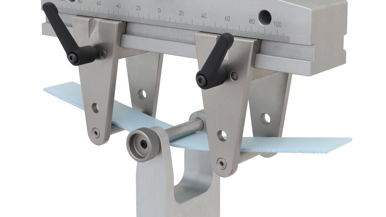
A guided bend test is a mechanical test used during procedure qualification (PQR) and welder qualification. A prepared specimen — a strip cut across the weld — is bent around a former of a defined diameter until it reaches a set bend angle, usually 180 degrees. The outer (convex) surface of the bend is where discontinuities open up and become visible.
This is not a substitute for the non-destructive testing that qualifies a production weld. It is a one-time, destructive check that the welding procedure and the welder can produce a joint with adequate ductility and freedom from the discontinuities a bend will expose, such as lack of fusion or excessive porosity clustered at the surface.
Face, root and side bends
- Face bend — the specimen is bent with the weld face on the convex (tension) side. It tests the weld cap and the fusion line closest to the surface the inspector normally examines visually.
- Root bend — the specimen is bent with the weld root on the convex side. It targets the region most exposed to lack of root fusion or root concavity, which is often the least accessible for visual or radiographic inspection depending on joint geometry.
- Side bend — used for thicker material where a full-thickness face or root bend is impractical. The specimen is a transverse slice through the full weld thickness, bent on its edge, so the convex surface passes through the whole cross-section including the interior of a multi-pass weld.
Which combination a code requires depends on material thickness, welding process and joint type. [Assumption / ipotesi] A specific procedure or welder qualification will reference one governing code’s bend requirements (for example ASME Section IX QW-160 or AWS D1.1 Clause 4/Annex bend provisions); confirm the applicable edition and thickness range before selecting the bend type, because the same joint can require different bend combinations under different codes.
Specimen preparation and what disqualifies a test before it starts
Preparation decisions that a welding coordinator should control, not leave to the machine shop’s habit:
- Location — specimens are removed from defined positions along the test coupon, avoiding the run-on and run-off tabs where arc-starting and stopping artifacts concentrate.
- Edge condition — sharp corners from machining act as stress risers and can start a crack that has nothing to do with the weld. Codes generally require radiused or otherwise conditioned edges.
- Reinforcement removal — face and root bend specimens typically have weld reinforcement machined flush so the bend load is not concentrated by a cap profile.
- Thickness reduction for thick material — a full-thickness face or root bend becomes impractical once the material is thick enough that a code-compliant former diameter and bend angle would demand more elongation than the outer fibre can sustain, and the specimen and former sizes involved stop being practical for standard test equipment. A side bend keeps the test practical by bending a thin transverse slice on edge, so the tested cross-section still samples the full weld thickness. Using the wrong bend type for the thickness invalidates the exercise even if the joint is sound.
An improperly prepared specimen can fail for reasons unrelated to weld quality, which then forces an unnecessary requalification. The WPS/PQR digital traceability guide covers how to keep the specimen, its removal location and its result linked to the exact PQR revision it supports, so a repair or a repeat test does not get attached to the wrong record.
Reading the result: what “acceptable” actually means
Acceptance criteria are stated as a maximum discontinuity length (and sometimes width) visible on the convex surface after bending, typically measured in any direction, with separate allowances for corner cracks depending on the code. [Assumption / ipotesi] Exact length limits and corner-crack exceptions vary by code and edition — do not apply a limit from memory; read it from the specific clause the governing WPS/PQR cites.
A test report should record, at minimum: the bend type, former diameter and bend angle used, the measured length and location of any discontinuity found, the accept/reject call against the cited clause, and the identity of the coupon and welder or procedure it qualifies. A pass/fail word with no measurement is not a defensible qualification record.
Where bend testing fits next to in-process monitoring
Bend testing qualifies the procedure and the welder once, under controlled conditions, before production starts. It does not tell you whether every subsequent production weld was made under the same conditions the qualified procedure assumed — heat input drift, interpass temperature excursions or an undetected parameter change can still produce a joint outside the qualified envelope even though the WPS on file is correct.
Real-time thermal monitoring closes that gap by comparing every production weld’s thermal signature against the profile observed during qualification, flagging the ones that drift before they reach final inspection. The weld evidence pack guide describes how a qualification record, in-process monitoring data and final inspection evidence can be organized into one retrievable package for an ISO 3834 or EN 1090 audit, rather than being scattered across a lab report, a production log and an inspector’s notes.
Common failure modes and fixes
- Wrong bend type for the thickness — a face/root bend attempted on material that calls for a side bend under the governing code. Fix: confirm the thickness threshold in the applicable clause before cutting specimens.
- Sharp-edged specimens — machining leaves square corners instead of the required radius. Fix: add edge conditioning to the specimen preparation checklist and verify it before testing, not after a failure.
- Weld-start artifacts included in the specimen — run-on/run-off regions carry arc-strike and tie-in irregularities that are not representative of steady-state welding. Fix: mark and exclude these regions when laying out specimen removal.
- Result recorded without measurement — “passed” with no discontinuity length undermines the record during an audit. Fix: require a measured value and the cited clause on every report, even when the result is a clean pass.
Sources
- ASME Boiler and Pressure Vessel Code, Section IX — bend test methods and acceptance for procedure and welder qualification; verify the applicable edition and QW paragraph.
- AWS D1.1, Structural Welding Code — Steel — bend test provisions for qualification, Clause 4 and applicable annexes; verify the applicable edition.
- Therness digital welding quality records guide — WPS/PQR and continuity traceability method.
- Therness weld evidence pack guide — organizing qualification, monitoring and inspection evidence.
- Therness EN 1090 weld traceability guide — joint-ID-based record linking for FPC audits.
Hero/OG photo: “Biegevorrichtung TH165” by Ingeniero-aleman, Wikimedia Commons, CC BY-SA 3.0, cropped for format.
Keep qualification evidence and production monitoring in one record
Therness can help connect PQR/WPS qualification data with in-process thermal monitoring so production welds stay inside the qualified envelope.
Talk to a welding monitoring specialistTherness solution: Welding monitoring system — Every weld inspected in the cycle, with defect flags and the ISO 3834 / ISO 17635 evidence kept per weld.