Reading a burn-through sequence frame by frame turns a single blurred failure into four distinct, separately explainable stages — and once you can name the stages, you can say which one a monitoring system has to catch and how much time it actually has to do it. At ordinary video speed, or to the naked eye, burn-through looks like one event: the weld pool was fine, and then there was a hole. High-speed footage takes that instant apart and shows it as a sequence with a beginning, a middle, and an end, each with its own visible signature.
This matters because the stages do not carry the same value. The final frame — metal dropped through, hole open — is the one an inspector eventually finds. The frames before it are the ones a real-time system can act on. Learning to read the sequence is the practical skill behind that distinction.
Key takeaways
- Burn-through on video is four stages, not one event: over-widening, underside sag, window opening, drop-through.
- The over-widening stage runs for multiple frames before any hole exists, which is the actual detection window.
- Standard 30-60 fps video compresses the whole sequence into one or two frames and shows that it happened, not how.
- The same sequence plays out differently on a tee joint than on a butt joint, because the root geometry differs.
- A decision on which signal catches which stage should drive camera and monitoring selection, not the reverse.
- Excess penetration is the same sequence stopping one stage short of a full window.
- Reading the sequence once, carefully, is what makes a verification pass on a monitoring system meaningful rather than a formality.
The four stages of a burn-through sequence, frame by frame

Slowed down, the footage above resolves into a sequence any welding engineer can learn to read on their own line’s video, not just this one.
Stage 1 — the pool over-widens
The first visible change is width, not depth. The pool grows past the outline it held for the preceding passes of the sequence, spreading laterally because the heat arriving exceeds what the surrounding parent material can conduct away. Nothing looks broken yet — this stage can be mistaken for ordinary process variation if you are only glancing at the weld, which is exactly why it is worth learning to recognise on purpose.
Stage 2 — the underside sags
As the pool keeps growing, surface tension — the force that has been holding the liquid metal against gravity from underneath — starts losing the fight. The underside of the joint bulges outward. This is still, technically, recoverable: a travel-speed correction or a heat-input reduction at this point stops the sequence before it becomes a defect at all.
Stage 3 — the window opens
Past a certain point the bulge thins to the point of failure and a gap opens where the root should be fusing the two members together. This is the frame where “excessive heat input” stops being an abstraction and becomes a visible loss of the joint itself.
Stage 4 — drop-through
Molten metal falls through the window, and what remains is a hole rather than a weld. On thin-gauge material this whole four-stage sequence, start to finish, occupies a small fraction of a second — which is the entire argument for watching it in frames rather than relying on what a welder can perceive in real time.
What drives the sequence: heat, thickness, and joint geometry
The four stages above are the same physics playing out slightly differently depending on where the weld sits.
Thin sections that have not cooled between passes
A section that stayed hot from a previous pass reaches the same collapse point at a lower arc energy than a cold start would need. Sequencing passes to avoid stacking heat in one area, and tracking interpass condition on thin material, addresses this directly.
Thickness transitions welded on one procedure
A procedure qualified for the thicker member of a joint, carried across a step down to thinner material without a separate parameter set, delivers more energy than the thin side can support. Qualify and apply a distinct procedure either side of the transition rather than assuming one set of parameters covers both.
Tee and fillet joints versus butt joints
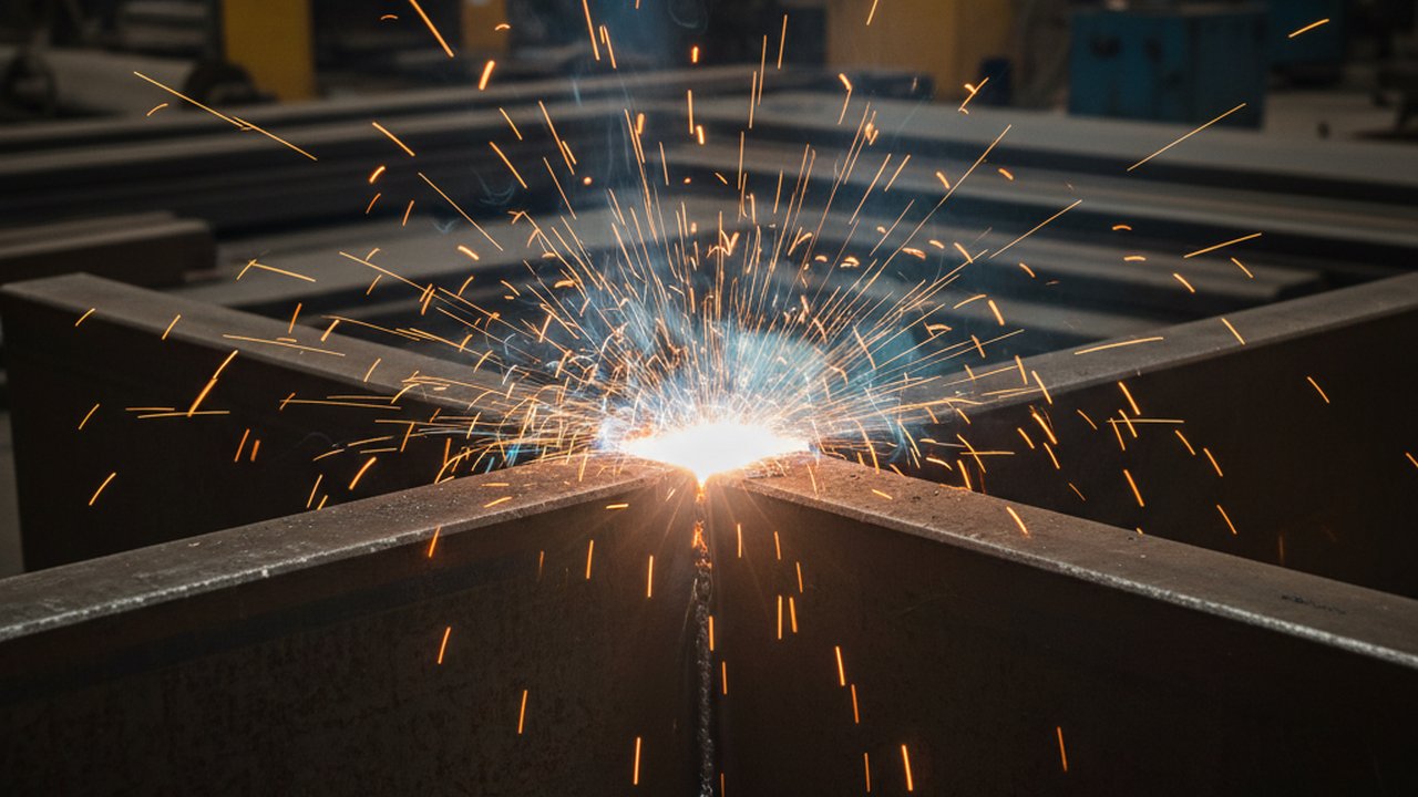
A tee joint — the configuration in the clip above — puts the vulnerable root at a fillet supported by two members meeting at an angle, rather than the single continuous plane a butt joint presents. The same heat-versus-thickness imbalance reaches its collapse point at a different stage of the pass, because the geometry holding the pool back has changed even though the four-stage sequence itself has not.
None of this is a substitute for classification. ISO 6520-1 assigns burn-through its own reference number in the group covering imperfect shape and dimension, and the reference card for it lists the same cause pattern in more structured form: 510 — burn-through.
Reading the sequence in real time: which signal catches which stage
Different detection methods see different stages of the sequence, and knowing which is what turns “we have a camera on the cell” into an actual answer to “will we catch this before it becomes a hole.”
| Stage | What the frame shows | Earliest signal that can see it | What it is good for |
|---|---|---|---|
| 1 — Over-widening | Pool spreads beyond its stable outline | In-process thermal imaging tracking pool temperature and area | Catching the precursor early enough to correct the pass in progress |
| 2 — Underside sag | Root bulges outward, still intact | High-speed weld-pool imaging of the topside pool geometry | Confirming the trend from stage 1 is continuing, not settling back |
| 3 — Window opens | Gap appears where the root should fuse | Direct visual observation, in process or immediately after | The point at which the pass should already have been stopped or corrected |
| 4 — Drop-through | Hole is open, metal has fallen through | Post-weld visual testing to ISO 17637 | Confirming the defect after the fact, for repair sizing and root-cause records |
Radiography adds little at any of these stages for burn-through specifically: the hole is already visible without it, so its value here is confirming the extent of metal loss for repair planning rather than detecting the imperfection in the first place.
Failure modes and fixes
- The camera runs at ordinary video frame rates. Thirty or sixty fps compresses the whole sequence into one or two frames. Fix: use a camera fast enough to resolve stage 1 and stage 2 as separate frames on your material.
- The system tracks a single-point temperature. A fixed hot-spot reading can miss the pool widening laterally. Fix: track pool area or width, not one fixed point.
- Interpass condition is not tracked on thin material. A section that stayed hot reaches stage 1 at a lower energy than a system checking only arc parameters expects. Fix: fold interpass temperature into the same monitoring pass.
- Every joint runs the same procedure across a thickness transition. The thin side reaches stage 1 well before the thick side would. Fix: qualify and apply a separate parameter set either side of the transition.
- The alert fires after the pass, not during it. Fix: route the stage-1 signal to an interlock the PLC or robot controller can act on while the pass is still running, not to a post-weld report.
Step-by-step: setting up frame-by-frame review on your own line
- Choose the joint and thickness you are most worried about — thin sheet, tee and fillet joints, and thickness transitions, where the sequence plays out fastest.
- Confirm your camera’s frame rate against the sequence duration. A camera at ordinary video rates will not separate stage 1 from stage 2 if the whole collapse takes a fraction of a second on your material.
- Film a deliberately marginal pass, pushing heat input or travel speed slightly past normal under controlled conditions, to capture stage 1 and stage 2 without necessarily reaching stage 4.
- Step through the footage and mark the frame where the pool first exceeds its stable width — your stage-1 reference point.
- Compare that frame against your in-process monitoring’s timestamp. A lag of more than a pass or two means the real detection window is narrower than the footage suggests.
- Set the alert threshold from that comparison, not a generic default, and route it to whatever can act fastest — an operator cue on a manual pass, a PLC or robot interlock on a mechanised one. Repeat the review separately for thickness transitions and tee joints, since the geometry moves where stage 1 begins.
Verification: proving the system catches stage 1, not just stage 4
Verification here asks one specific question: does the monitoring signal you rely on actually fire during stage 1 or stage 2, or does it only confirm stage 4 after the fact? Answering it needs the same paired comparison as the setup above, repeated on a schedule rather than once at commissioning.
Run a deliberately marginal pass, capture it on high-speed video alongside whatever the production monitoring reports, and check the timestamps against each other. A system that only agrees with the video at the stage-4 frame is not giving you the precursor it is supposed to provide — it is giving you a slower, more expensive way to find out the weld already failed. Re-run the check whenever the joint design, thickness, or procedure changes, because the frame at which stage 1 begins moves with all three.
Standards that classify and govern acceptance
ISO 6520-1 — classification
ISO 6520-1 is the international vocabulary for weld imperfections: it assigns burn-through its own reference number within the group covering imperfect shape and dimension, giving every fabricator, inspector, and monitoring system the same term for the same defect. The ISO 6520-1 reference card on this site covers its scope in more depth.
ISO 5817 — acceptance levels
ISO 5817 sets quality levels, indexed by ISO 6520-1 reference number, for weld imperfections in fusion-welded joints in steel, nickel, titanium and their alloys — beam welding is outside its scope — without this article restating its acceptance values — those belong in the standard itself. The ISO 5817 reference card covers where the standard applies and how its levels are structured.
AWS D1.1 — structural soundness
AWS D1.1 governs weld soundness requirements for structural steel in North American practice; for material below its thickness range, the companion code AWS D1.3 covers sheet steel instead. The AWS D1.1 reference card on this site summarises its scope.
Beyond the standards themselves: TWI Job Knowledge for welding practice, the International Institute of Welding and the European Welding Federation for qualification frameworks, ASNT and the NDT Resource Center for the inspection side, the NIST Engineering Laboratory and NIST Sensor Science Division for the measurement science behind thermal detection, and the AWS primer on weld defects for a plain-language overview.
From reading the sequence to catching it live
Reading footage after the fact is a training and diagnostic exercise. Catching stage 1 while the pass is still running is what an in-process system is for: a welding camera resolves the pool geometry itself, while HeatCam IR-C reads the surrounding heat field for the temperature climb that precedes the visible sag. HeatCore AI scores that combined signal in real time and raises the alert while the operator or robot controller can still act on it, instead of waiting for a post-weld report to confirm what already happened.
For the causes and prevention side of burn-through beyond this frame-by-frame reading, see burn-through in welding: causes, prevention, and monitoring. For the full video this article is built around, see welding burn-through under a high-speed camera.
FAQ
What are the visible stages of a burn-through sequence on high-speed video? Four, in order: the pool over-widens beyond its normal outline, the underside bulges as surface tension loses its grip, a window opens where the root should be fused, and molten metal drops through, leaving a hole. Each stage is a distinct frame range, not one instant.
How early does the pool over-widen before burn-through actually happens? Measurably earlier than the hole itself, though the exact lead time depends on thickness and travel speed. The pool grows past its stable width for several frames before the underside gives way, which is the window a monitoring system has to catch rather than the final collapse.
What frame rate is needed to capture a burn-through sequence usefully? Standard video at 30 or 60 fps compresses the whole collapse into one or two blurred frames, which shows that it happened but not how. A camera in the low hundreds of frames per second resolves the over-widening and sag stages as separate, readable frames.
Can a burn-through precursor be told apart from normal pool widening on thin sheet? Yes, by trend rather than by a single frame. Normal pool width on thin sheet varies within a stable band pass to pass; a precursor is a sustained climb past that band that keeps growing rather than settling back, visible across consecutive frames before any hole forms.
Does a burn-through sequence look the same on a tee joint as on a butt joint? The stages are the same, but the geometry differs. A tee joint puts the vulnerable root at a fillet where support comes from two members instead of one continuous plane, so the same heat-versus-thickness imbalance reaches collapse at a different point in the pass.
What should a monitoring system do once it flags a burn-through precursor? Raise the alert on the pass in progress, not only in the after-weld report. On a mechanised or robotic cell that means an interlock the PLC or robot controller can act on immediately; on a manual pass it means an operator cue fast enough to correct travel speed or stop before the window opens.
Is a burn-through hole visible before the arc is extinguished? Often yes, from the topside, once the window opens, because losing the backing changes how the arc behaves and how light reflects off the pool. The visual cue still lags the thermal and geometric precursor by several frames, which is why watching the sequence beats waiting for the finished bead.
How is a burn-through sequence different from excess penetration on video? Excess penetration is the same heat-versus-thickness imbalance stopping short of a hole: the root bulges or sags but the parent material still holds. On frame-by-frame video the two share the early stages; whether the sequence stops at a proud, oversized root or continues to a full window is what separates them.
See the precursor before it becomes a hole
Therness combines high-speed pool imaging with in-process thermal monitoring so a burn-through sequence is flagged at stage one, not found at final inspection.
Talk to an engineerTherness solution: Welding camera — Thermal and high-speed imaging that watches the arc, the pool and the cooling seam while the weld is made.
Frequently Asked Questions
What are the visible stages of a burn-through sequence on high-speed video?
Four, in order: the pool over-widens beyond its normal outline, the underside bulges as surface tension loses its grip, a window opens where the root should be fused, and molten metal drops through, leaving a hole. Each stage is a distinct frame range, not one instant.
How early does the pool over-widen before burn-through actually happens?
Measurably earlier than the hole itself, though the exact lead time depends on thickness and travel speed. The pool grows past its stable width for several frames before the underside gives way, which is the window a monitoring system has to catch rather than the final collapse.
What frame rate is needed to capture a burn-through sequence usefully?
Standard video at 30 or 60 fps compresses the whole collapse into one or two blurred frames, which shows that it happened but not how. A camera in the low hundreds of frames per second resolves the over-widening and sag stages as separate, readable frames.
Can a burn-through precursor be told apart from normal pool widening on thin sheet?
Yes, by trend rather than by a single frame. Normal pool width on thin sheet varies within a stable band pass to pass; a precursor is a sustained climb past that band that keeps growing rather than settling back, visible across consecutive frames before any hole forms.
Does a burn-through sequence look the same on a tee joint as on a butt joint?
The stages are the same, but the geometry differs. A tee joint puts the vulnerable root at a fillet where support comes from two members instead of one continuous plane, so the same heat-versus-thickness imbalance reaches collapse at a different point in the pass.
What should a monitoring system do once it flags a burn-through precursor?
Raise the alert on the pass in progress, not only in the after-weld report. On a mechanised or robotic cell that means an interlock the PLC or robot controller can act on immediately; on a manual pass it means an operator cue fast enough to correct travel speed or stop before the window opens.
Is a burn-through hole visible before the arc is extinguished?
Often yes, from the topside, once the window opens, because losing the backing changes how the arc behaves and how light reflects off the pool. The visual cue still lags the thermal and geometric precursor by several frames, which is why watching the sequence beats waiting for the finished bead.
How is a burn-through sequence different from excess penetration on video?
Excess penetration is the same heat-versus-thickness imbalance stopping short of a hole: the root bulges or sags but the parent material still holds. On frame-by-frame video the two share the early stages; whether the sequence stops at a proud, oversized root or continues to a full window is what separates them.