Tubular connections concentrate load, geometry and access in one intersection. A branch can meet a chord as a T, split from it as a Y, or arrive from two sides as a K. The drawing may look simple; the production record is not. Fit-up, bevel condition, sequence, heat input and inspection all affect whether the chosen detail can be made repeatedly under the approved procedure.
This guide answers a practical question: for a K/T/Y tubular joint under AWS D1.1, how should the joint be selected and what process evidence should be recorded to decide whether the chosen setup is fit for production? It is a decision and evidence guide, not a substitute for the project design, the current AWS D1.1 edition or the approved WPS.
Start with the load path and the access
A joint name is a geometric description, not a design decision. Begin with the force entering the branch, the force leaving through the chord, and the fatigue category or consequence class in the project specification. Then test whether the detail can actually be fitted, tacked, welded and inspected with the access available on the real component.
| Question | Why it changes the choice |
|---|---|
| Where does the branch load enter and leave? | The load path controls branch angle, weld length and local stress at the chord. |
| Can the weld be reached around the full intersection? | Restricted access may rule out a detail that is easy to draw but difficult to execute consistently. |
| Can both sides be welded or inspected? | A K detail has two branch-to-chord weld regions; a one-sided sequence changes preparation and evidence needs. |
| What does the fatigue and inspection plan require? | A detail that is acceptable for static loading may need tighter process control and examination for cyclic service. |
A T joint is often the clearest starting point when one branch meets a chord and the load path is direct. A Y joint changes the branch angle and can improve alignment with the applied force, but the oblique intersection can make fit-up and torch access more sensitive. A K joint brings two branches into a common chord and leaves two interacting weld regions whose sequence and heat accumulation must be controlled.
These are starting descriptions only. The engineer of record, the fabrication procedure and the project specification decide the final detail. Do not infer that a K, T or Y label alone makes the joint prequalified.
Confirm the governing AWS D1.1 route
AWS D1.1 is a structural steel welding code. Before a production trial, record the edition and clauses named by the project, the base-metal group, filler classification, process, position, thickness range and whether the WPS uses a prequalified detail or a procedure qualified by test. The joint geometry on the drawing must match the qualified or prequalified route; a change in groove, backing, root opening, process or essential variable can require a review or a new qualification.
The production packet should keep these records together:
- approved drawing and revision, including branch and chord dimensions;
- WPS and supporting qualification record, with the applicable AWS D1.1 route;
- material and filler certificates, joint preparation and fit-up checks;
- welder or welding-operator qualification and station identification;
- inspection and NDT plan, hold points and acceptance criteria.
AWS D1.1 defines the welding and inspection framework; it does not choose the connection for the structure. The design load case, fatigue requirement, access and project specification remain the inputs to joint selection.
Build a parameter window before the first production joint
A WPS gives a qualified window, not one magic setting. For a tubular joint, the window should cover the actual thickness, position, consumable, shielding, sequence and travel path. Record the limits that matter to the joint: current, voltage, travel speed, wire feed where applicable, heat input convention, preheat, interpass temperature and any stop or restart rule.
A worked calculation is useful because it makes units visible. Using current in amperes, voltage in volts and travel speed in millimetres per minute:
heat input (kJ/mm) = voltage × current × 60 / (1000 × travel speed)For an illustrative check, 24 V, 220 A and 300 mm/min gives 1.06 kJ/mm before a process-efficiency factor. It is a calculation example, not a limit for every tubular joint. The production decision compares the measured values and the procedure’s convention with the approved WPS/WPQR range.
The same record should show whether the thermal cycle stayed comparable as the torch moved around the intersection. A branch toe, chord sidewall and root region do not have the same heat sink. One average current and voltage entry for the whole joint can hide a local cold start, a dwell or heat accumulation near the final closure.
Record the joint, the process and the result together
A useful per-joint record answers three questions: which joint was made, how was it made, and what was found? Minimum fields are:
| Record group | Fields to retain | Decision it supports |
|---|---|---|
| Identity | Assembly, joint ID, drawing revision, branch/chord position, WPS revision | The evidence points to one physical intersection and one approved setup. |
| Fit-up | Members, dimensions, root opening, bevel, alignment, tack and preheat checks | The starting geometry was inside the procedure and drawing requirements. |
| Delivery | Welder/station, process, current, voltage, travel speed, wire feed, start/stop and restarts | The delivered process can be compared with the qualified window. |
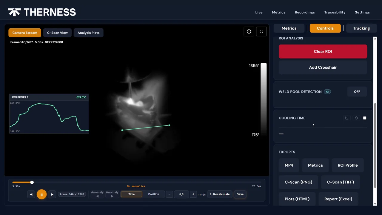
| Thermal | Field of view, calibration status, thermal trace, peak and cooling features, alarm time | A deviation can be located on the joint instead of inferred after inspection. |
| Inspection | Visual result, NDT method and report, indications, disposition, repair and reinspection | Process evidence remains linked to the acceptance decision. |
A thermal camera does not see inside every tubular intersection, and it does not replace the required visual or NDT method. Its value is earlier context: a thermal field that departs from the reference can flag a cold start, excess dwell or cooling change while the operator can still record the location and disposition.
For a broader architecture, see the real-time welding monitoring system and the welding parameter monitoring guide. For the inspection side, the AWS D1.1 acceptance guide explains why the governing table and loading class must stay attached to the record.
A controlled pilot before production release
Use one joint family and one approved procedure for the first pilot. Capture a reference set of sound joints under normal conditions, then introduce controlled changes that represent the risks you need to distinguish: a fit-up gap near its allowed limit, a planned travel-speed change inside the WPS window, or a restart that must be documented. Do not call a signal a defect because it looks different; compare it with the final visual and required NDT result.
Define the disposition before the pilot starts:
- what signal or parameter deviation creates an alarm;
- who can pause, repair or release the joint;
- which inspection result closes the alarm;
- which fields must be present before the record is accepted.
The outcome is a measured production decision: the setup is fit for the defined joint family, the window needs adjustment and requalification, or the evidence is not yet sufficient. That decision belongs to the responsible engineering and quality roles; monitoring supplies the trace, not the signature.
Connect tubular-joint evidence to the weld process
Tell us your joint family, process and evidence gap. Therness can help scope the thermal and parameter records around the approved welding procedure.
Discuss your monitoring setupTherness solution: Welding monitoring system — Every weld inspected in the cycle, with defect flags and the ISO 3834 / ISO 17635 evidence kept per weld.
Frequently Asked Questions
What is a K, T or Y tubular joint?
A tubular joint connects a branch member to a chord or another tube. In a T joint the branch meets the chord without continuing through it; in a Y joint the branch is inclined and the load path splits at the intersection; in a K joint two branch members meet a common chord and share the load path. The drawing and the governing specification define the actual geometry.
Does AWS D1.1 prescribe one joint shape for every tubular connection?
No. AWS D1.1 supplies requirements and qualification routes for structural steel welding, while the design engineer and project specification establish the connection geometry, loads, access and acceptance requirements. Use the applicable D1.1 provisions for the chosen detail instead of treating a generic K, T or Y sketch as a qualified joint.
How do I choose between a K, T and Y tubular joint?
Start with the load path, member sizes, fatigue class, access for fit-up and welding, and whether the branch can be welded from both sides. A K detail can balance two branch loads into a common chord, a T detail is often simpler where one branch carries the load, and a Y detail changes the branch angle and the available weld access. Final selection belongs in the design and fabrication review.
What process evidence should be recorded for each tubular joint?
Record the joint identifier and revision, drawing and WPS revision, base and filler material, welder or station, fit-up checks, preheat and interpass readings, delivered current, voltage and travel speed, thermal trace where installed, start and stop times, repairs and the final inspection result. Keep the records linked so an indication can be traced back to the process conditions at that location.
Can thermal monitoring prove tubular-joint acceptance?
No. A thermal record is in-process evidence: it shows whether the heat distribution and cooling pattern stayed inside the qualified process envelope and identifies where a deviation occurred. Visual testing and any required NDT still make the acceptance decision under the project specification and governing code.
How can I check heat input on a tubular weld?
Use the convention in the approved procedure. For a simple illustrative check, 24 V at 220 A and 300 mm/min gives (24 × 220 × 60) ÷ (1000 × 300) = 1.06 kJ/mm before any process-efficiency factor. That number is a calculation example, not an acceptance limit: compare the measured values with the WPS/WPQR range for the actual joint and process.
What is the minimum useful pilot for tubular-joint monitoring?
Choose one joint family and one qualified procedure, then record a reference set of sound joints before introducing controlled fit-up or parameter deviations. Define the alarm and disposition rules in advance, compare the in-process record with visual and required NDT results, and only then decide whether the signal is useful for production release.