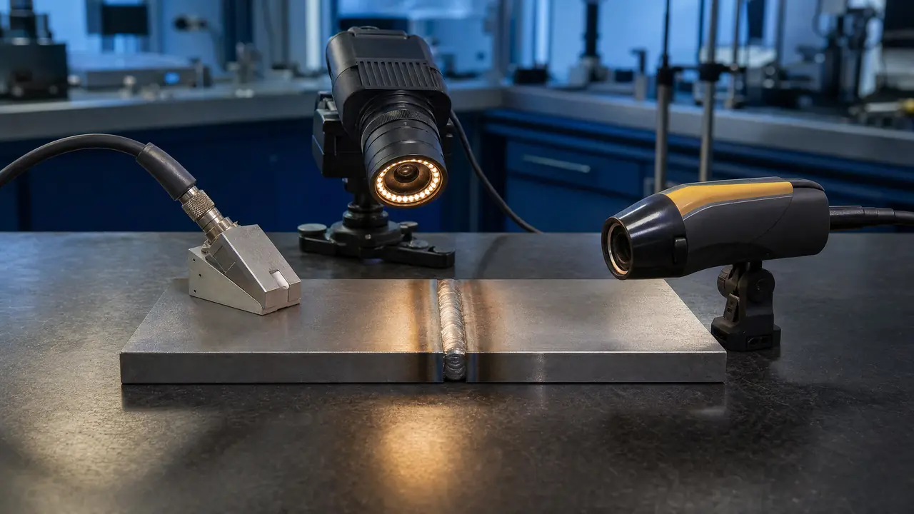
ISO 17635:2016 is the standard that answers “which inspection method do I use to check this weld, and how much of it do I need to inspect?” It sits directly above the five method-specific standards (ISO 17636 for radiography, ISO 17637 for visual, ISO 17640 for conventional UT, ISO 17641 for MPI, ISO 17642 for LPT) and the quality acceptance standards (ISO 5817, AWS D1.1, ASME).
What ISO 17635 covers:
- Selection of NDT method per imperfection type (porosity, crack, undercut, lack of fusion, etc.)
- Testing extent (percentage of weld to inspect) based on quality level and service condition
- Documentation and responsibility assignment
- Connection to ISO 5817 quality levels and ISO 14731 welding coordination
What it does not cover:
- Acceptance criteria (those are in ISO 5817 or your governing code)
- The detailed technique of each method (those are in the method-specific standards)
- Thermographic monitoring or in-process observation (ISO 17635 addresses post-weld NDT only)
Method selection logic:
Certain imperfection types are best detected by certain methods:
| Imperfection | Best method | Why |
|---|---|---|
| Porosity (2011–2015) | Radiography (RT) | Round cavities show as dark indications; easy to size and count |
| Lack of fusion (3xxx) | Ultrasonic (UT) or PAUT | Planar interface; UT time-of-flight gives clear signals |
| Cracks (1xxx) | Ultrasonic, MPI, LPT | UT for internal; MPI/LPT for surface |
| Undercut (5xxx) | Visual (VT) | Surface-breaking; directly observable |
| Spatter (6xxx) | Visual | Surface; observable without NDT |
The standard does not say “use only RT for porosity” — it says RT is the recommended method for porosity given how a rounded, volumetric cavity interacts with each method, and it gives alternatives with guidance on their limitations rather than a single mandatory choice.
Surface methods: magnetic particle and liquid penetrant testing
ISO 17635’s method-selection table is not limited to the volumetric methods. Two surface methods cover imperfections that radiography and ultrasonic testing are not the right tool for, and Clause 5 routes to them by material and imperfection type rather than by habit.
Magnetic particle testing (MPT) works only on ferromagnetic materials — carbon and low-alloy steels, most structural sections. A magnetic field is induced across the weld and ferrous particles are applied; a surface-breaking or near-surface discontinuity distorts the field and the particles collect along the leakage line, making a crack or a lack-of-fusion break in the surface visible under the right light. It is fast, needs no consumables beyond the particle medium, and is the standard method for surface and near-surface cracking on structural steel.
MPT does not work on austenitic stainless steel, aluminium, or other non-magnetic materials, because there is no field to distort. Liquid penetrant testing (LPT) fills that gap: a penetrant liquid is applied to the surface, drawn into any surface-breaking discontinuity by capillary action, the excess is removed, and a developer draws the trapped penetrant back out to the surface where it becomes visible. LPT works on any non-porous material regardless of magnetic properties, which is why it is the surface method specified for stainless structural work and non-ferrous fabrication where MPT is not an option.
Both methods share a limit ISO 17635 is explicit about: they find only surface-breaking discontinuities. A crack or lack-of-fusion plane one millimetre below the surface is invisible to either method, which is exactly why Clause 5 pairs a surface method with a volumetric method (RT, UT, or PAUT) rather than treating surface testing as sufficient on its own for anything beyond visually-governed acceptance.
Testing extent and quality level interaction:
The percentage of weld to inspect depends on:
- Quality level (ISO 5817 B/C/D) — higher level = higher testing percentage
- Service condition (static, cyclic, high-temperature, etc.)
- Imperfection consequence — critical defects get 100%; others may be sampled
For a pressure vessel (ASME Section VIII) under Level B, all welds typically require 100% VT plus 100% radiographic or UT on critical joints and seams. For a non-critical structural weld under Level D, you might inspect 10–25% by RT and rely on 100% VT.
ISO 17635 does not specify the percentages directly; it directs you to the applicable governing code (your pressure code, your structural standard, your customer specification) to determine the extent. The extent is not universal; it depends on the project.
Where the extent decision actually gets documented
Selecting a method per Clause 5 answers “how do I check this imperfection type.” It does not by itself create the audit trail an ISO 3834 assessor or a customer inspector will ask for. That trail is the fabricator’s own quality plan — the Inspection and Test Plan or Production Quality Plan required under ISO 3834 — and ISO 17635 Clause 6 requires that the plan name, for each weld or weld category, which imperfections are being examined, by which method, and at what extent, before welding starts rather than as an after-the-fact justification once a weld has already been made.
This is also where in-process monitoring earns its place in the quality system without being mistaken for NDT. A shop running continuous parameter and thermal monitoring, such as a welding monitoring system, produces a process record for every weld — not a pass/fail NDT result, but evidence that the qualified procedure was followed throughout the pass. An ISO 3834 quality plan can reference that process record as supporting evidence for the fabricator’s process control commitments, alongside — never instead of — the ISO 17635 NDT results that the plan’s testing-extent table actually requires.
Reading the extent table your code gives you
ISO 17635 does not print one universal extent table because none exists across all applications; instead it directs you to the extent table in your governing code or specification, and Clause 6 requires the plan to cite which one. In practice this means the same imperfection type, on the same quality level, can carry a different testing percentage on a pressure vessel job than on a structural steel job, because the two codes weigh the consequence of a missed defect differently. A welding coordinator moving between sectors cannot assume the last project’s extent carries over; the first step on any new job is identifying which code governs and pulling its extent table, not assuming ISO 17635 supplies one directly.
This also means two fabricators working to the same ISO 5817 quality level can run legitimately different testing extents if their governing codes differ, and neither is wrong. What ISO 17635 standardises is the selection logic and the documentation requirement, not the percentage.
Key clauses and process workflow:
- Clause 4: Responsibilities — who orders the NDT (typically the QA/welding coordinator per ISO 14731), who performs it (certified NDT level 2/3 per ISO 9712), who evaluates results
- Clause 5: Selection of method per imperfection — the decision table
- Clause 6: Planning and extent — requires a documented plan (your ITP or PQP) stating which imperfections are examined, which methods, which extents
- Clause 7: Execution of testing — requires that method-specific standards (ISO 17636, etc.) are followed
- Clause 8: Evaluation and reporting — results recorded, linked to the quality standard (ISO 5817), decisions traceable
Personnel and sign-off responsibility
Clause 4 splits responsibility three ways, and audits fail most often at the boundary between them, not inside any one role. The party that orders the NDT — typically the welding coordinator under ISO 14731, or the customer’s own quality representative on some contracts — sets the extent and method per the ITP. The NDT operator, certified under ISO 9712 at the level the code requires (Level 2 as a minimum for making an accept/reject call, Level 1 permitted only for assisting under supervision), performs the test and produces a technically valid result. The evaluator, who may or may not be the same certified individual, compares that result against the quality standard — ISO 5817 or the governing code’s own acceptance limits — and records the disposition.
An auditor checking this chain looks for three things: that the person who ordered the test had the authority to do so, that the person who performed it held current ISO 9712 certification at the required level on the date of the test, and that the accept/reject decision references a specific acceptance criterion rather than a general judgment call. Any one of the three missing is a nonconformity regardless of whether the weld itself was sound.
Typical workflow:
- The welding procedure is qualified per ISO 14731 or your code (ASME Section IX, etc.)
- The ITP (Inspection & Test Plan) specifies NDT extent per imperfection type and quality level
- NDT is performed per the method standard; results are recorded
- Results are evaluated against ISO 5817 limits (or your code’s acceptance) by a qualified inspector
- Accepted welds move forward; rejected welds are dispositioned (repair or rework)
Thermographic monitoring and ISO 17635:
ISO 17635 is the standard for post-weld NDT only. In-process monitoring (thermal imaging, vision systems, arc monitoring) is a quality control tool that flags process drift and risk in real time; it complements but does not replace ISO 17635 testing. A weld that passes real-time thermal monitoring may still be examined per ISO 17635 at final inspection — the in-process data supports the quality evidence but does not substitute for the code-required final check. See thermography for NDT testing for how in-process and post-weld inspection work together.
Integration with other standards:
- ISO 5817: Sets acceptance limits; ISO 17635 determines how to check against them
- ISO 9712: Specifies the qualification and certification of NDT personnel (Level 2 minimum for making accept/reject decisions; Level 1 for assisting)
- ISO 3834: Requires the fabrication shop to have a quality plan that includes NDT extent and method selection; ISO 17635 is the tool
- EN 1090 / ASME: Mandate which quality level and NDT extent apply to your specific application (execution class, pressure rating, service condition, etc.)
Common misunderstandings:
- “ISO 17635 says 100% UT on all welds” — No. The extent is determined by your project code/spec, not by ISO 17635 itself.
- “We use RT for everything” — Possible under your spec, but ISO 17635 recommends method selection per imperfection type for cost and detection efficiency.
- “Real-time cameras satisfy ISO 17635” — No. Thermal monitoring is preventive; ISO 17635 post-weld NDT is confirmatory. Both are valuable; they are not interchangeable.
A worked example: two projects, same imperfection, different extent
Consider lack of fusion found in a structural steel joint under one project governed by a national building code at a moderate consequence class, and the same imperfection type in a pressure-retaining joint on an ASME Section VIII vessel. ISO 17635’s Clause 5 sends both projects to the same method family — ultrasonic testing, because lack of fusion is a planar discontinuity UT is well suited to detect. But Clause 6 sends the two projects to different governing codes for the extent decision, and those codes weigh a missed lack-of-fusion indication very differently: a structural connection under normal service load has a different failure consequence than a pressure boundary joint that fails under an internal pressure load with no warning. The result is that the vessel joint can require full-length UT while the structural joint requires only a sampled percentage, even though both are the same imperfection type on the same quality level, examined by the same method, under the same ISO 17635 selection logic. This is the concrete version of the point the earlier sections make in the abstract: ISO 17635 standardises the “how” and the “who,” and the governing code — not ISO 17635 itself — sets the “how much.”
Next steps:
When you are assigned an ISO 17635 inspection responsibility:
- Read the ITP / PQP to understand your project’s NDT extent and methods
- Verify that your project code (ASME, EN 1090, API, AWS) defines the extent; ISO 17635 refers you to that code
- Select your NDT methods per Clause 5 (the decision table)
- Ensure your NDT personnel hold ISO 9712 certification at the required level
- Record all results and link them to your quality acceptance standard (ISO 5817 or your code)
For the five method-specific standards and how each one works in detail, see ISO 17637 (visual), ISO 17636 (radiographic), ISO 17640 (conventional ultrasonic), and phased-array ultrasonic testing.
See Real-Time Process Evidence Alongside Your NDT Plan
Therness continuous parameter and thermal monitoring gives you a per-weld process record that supports your ISO 3834 quality plan alongside the NDT results ISO 17635 requires. Book a demo to see it on your own joints.
Book a demoTherness solution: Welding monitoring system — Every weld inspected in the cycle, with defect flags and the ISO 3834 / ISO 17635 evidence kept per weld.