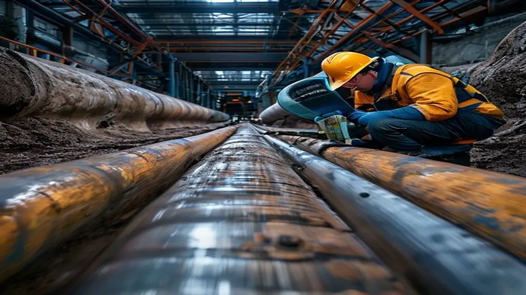
A pipeline weld monitoring camera captures what radiography cannot: the process conditions during welding, not just the result after the arc stops. Under API 1104, every girth weld on an oil and gas transmission pipeline must meet strict acceptance criteria verified by radiographic or ultrasonic testing. What the standard does not mandate — but what high-consequence area (HCA) regulations and operator quality management systems increasingly require — is objective in-process evidence that WPS parameters were maintained throughout each pass.
This guide explains where inline thermal monitoring fits the API 1104 compliance framework, what parameters a welding camera captures during pipeline girth welding, and how to implement a monitoring system that generates traceable evidence without disrupting mechanized GMAW or FCAW welding cycles.
Key Takeaways
- API 1104 Section 9 sets acceptance criteria for discontinuities detected by NDT; monitoring camera data provides upstream evidence that process parameters stayed within WPS-qualified limits during each pass.
- Preheat and interpass temperature are the two most common process control failures on pipeline girth welds — thermal imaging captures both continuously across the full joint circumference.
- A pipeline weld monitoring camera reduces API 1104 repair rates by flagging parameter excursions in real time before the pass is completed and capped.
- Inline monitoring does not replace RT or AUT — it is an upstream evidence layer that reduces defect occurrence while your NDT program verifies the completed joint.
- PHMSA regulations for HCA pipeline segments and most operator quality management systems require in-process documentation that monitoring camera data directly satisfies.
- Decision framework: mechanized girth welds above DN 300 (12 inches) and wall thickness above 10 mm on X70 or higher grade steel show the highest monitoring ROI.
- Implementation requires camera positioning protocol, WPS threshold configuration, and weld-number-to-monitoring-session traceability before the first arc on production pipe.
Table of Contents
- What API 1104 Requires for Pipeline Weld Quality
- Where Inline Monitoring Fits the API 1104 Framework
- What a Pipeline Weld Monitoring Camera Measures
- Decision Framework: Which Welds Need Inline Monitoring
- Common Failure Modes and Fixes
- Implementation Step-by-Step
- FAQ
What API 1104 Requires for Pipeline Weld Quality
API 1104 — Welding of Pipelines and Related Facilities is the governing welding standard for onshore oil and gas pipeline construction in North America and widely adopted internationally alongside DNV-ST-F101 for offshore applications. Its structure separates process control requirements from inspection requirements in a way that matters for understanding where monitoring cameras add value.
Process control (Sections 5–7): The contractor must qualify a Welding Procedure Specification (WPS) through a Procedure Qualification Record (PQR) demonstrating that the specified process, base materials, filler metals, preheat, heat input range, and post-weld heat treatment produce weld mechanical properties meeting API 1104 minimum requirements. Welders and welding operators are qualified separately through performance qualification tests.
Inspection and acceptance (Section 8–9): Every production girth weld must be inspected. API 1104 Section 8 specifies inspection method selection — visual, radiographic, ultrasonic (AUT), magnetic particle, or liquid penetrant. Section 9 sets acceptance criteria for each method: maximum allowed porosity area, maximum slag inclusion length, maximum incomplete penetration height, and crack prohibition without exception.
The gap: API 1104 verification runs post-weld. It confirms the joint is acceptable; it does not directly monitor whether the WPS parameters that produced the qualified mechanical properties were maintained during production welding. That process control gap is where PHMSA regulations for HCA segments and operator quality plans impose in-process documentation requirements that monitoring cameras satisfy directly.
Complementary standards relevant to pipeline weld process control include ASME B31.4 for liquid petroleum piping, ASME B31.8 for gas transmission and distribution, and AWS D10.12 for low-hydrogen procedures on carbon steel pipe. ISO 3183 governs the line pipe steel specifications (API 5L equivalent in ISO nomenclature) that determine the WPS qualification range and minimum preheat requirements.
Where Inline Monitoring Fits the API 1104 Framework
Inline monitoring occupies a distinct role in the API 1104 quality chain: it is neither a substitute for WPS qualification nor a replacement for post-weld NDT. It is an in-process evidence layer that documents parameter compliance between the qualified procedure and the completed joint.
- WPS + PQR — establishes qualified parameter ranges (current, voltage, travel speed, preheat, heat input)
- Inline monitoring — documents that production welding stayed within those qualified ranges, pass by pass
- RT / AUT / UT — verifies the completed joint meets Section 9 acceptance criteria for discontinuities
- Traveler + archive — links monitoring records, NDT reports, and welder qualifications to the specific weld joint identifier
This architecture is consistent with the operator-driven quality management requirements that most major pipeline contractors now impose on their supply chain. When a joint in an HCA segment fails RT and is cut out, the repair disposition requires understanding whether the defect originated from a process deviation. Monitoring records answer that question with objective data rather than operator recollection.
For detailed API 1104 acceptance criteria and the inspection method selection logic, see our comprehensive guide on API 1104 pipeline welding acceptance criteria.
What a Pipeline Weld Monitoring Camera Measures
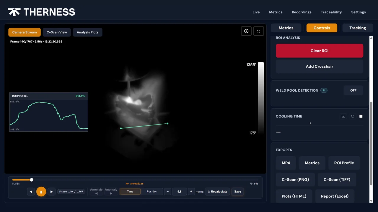
A thermal pipeline weld monitoring camera based on longwave infrared (LWIR) imaging measures temperature without contact, making it compatible with the rotating arc geometry of mechanized GMAW pipeline systems. The HeatCore AI seam-tracking clip shows the kind of per-frame record — seam position, width and offset in millimetres — that a girth pass would be read against, recorded here on a lab weld. The key parameters captured during a pipeline girth weld include:
Preheat Temperature
Before arc initiation on each joint, the camera verifies that the minimum preheat temperature specified in the WPS is achieved across the full circumference of the joint — not just at a single pyrometer contact point. Cold-side starts on high-strength pipeline steels (X70, X80) are a primary contributor to hydrogen-assisted cold cracking (HACC), the most serious weld defect in pipeline construction. Continuous circumferential preheat verification eliminates the cold-start gap that spot pyrometer checks cannot detect.
Interpass Temperature
On multi-pass girth welds, the camera tracks interpass temperature between each pass continuously. Exceeding the maximum interpass temperature limit — typically 250–300 °C for carbon steel, tighter for X80 and above — degrades HAZ toughness. Falling below the minimum interpass temperature on susceptible steels risks HACC. The monitoring system logs every interpass interval and triggers an alert before the next pass is initiated if temperature is out of range.
Heat Input Monitoring
Paired with electrical signal monitoring, the system calculates actual heat input per pass using the measured arc current, voltage, and travel speed. Heat input directly controls the weld thermal cycle and resulting HAZ microstructure — the same parameters defined in the WPS PQR that produced the qualified mechanical properties. Deviations from the qualified heat input range are flagged in real time and logged against the specific pass record.
Arc Event Detection
The monitoring system records arc start and stop times, travel direction, and arc outage events. Arc outages during a pipeline pass — particularly on mechanized GMAW — are a known source of lack-of-fusion at the restart location. Real-time detection allows the welding operator to address restarts immediately rather than discovering the defect at RT.
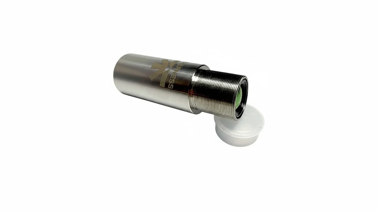
The Therness PoolDrop welding monitoring system integrates thermal imaging with electrical monitoring in a single data stream, generating a unified per-pass record that covers all the above parameters in a format directly linked to the joint identifier on the welding traveler. Compare it against the other cameras and monitoring units in the complete product catalog when specifying hardware for a given pipe diameter range. For integration architecture and deployment options across pipeline welding environments, see the welding monitoring system platform overview.
Decision Framework: Which Welds Need Inline Monitoring
Not all pipeline girth welds carry equal risk or benefit equally from inline monitoring. The following framework prioritizes monitoring deployment based on consequence level, geometry, and process type.
| Criterion | Higher Monitoring Priority | Lower Monitoring Priority |
|---|---|---|
| Pipe diameter | DN 300 (12 in) and above | Below DN 200 (8 in) |
| Wall thickness | Above 10 mm | Below 8 mm |
| Steel grade | X70 and higher | X52, X60 |
| Process type | Mechanized GMAW (multi-pass) | Manual SMAW, single-pass |
| Segment type | HCA, offshore, subsea, tie-in welds | Open-country, low consequence |
| Preheat requirement | >100 °C specified in WPS | No preheat required |
| Heat input control | Heat input range specified in PQR | No heat input limit in WPS |
| Repair history | Line segment with elevated RT repair rate | Established low-repair-rate line |
Highest ROI deployment: Mechanized GMAW girth welds on X70 pipe DN 400 (16 in) and above in HCA crossings — river crossings, highway crossings, population center segments. These welds carry the highest consequence of failure, the most demanding preheat and interpass temperature requirements, and the greatest opportunity to reduce repair rates through real-time parameter control.
For ISO 5817 weld quality levels and how they map to defect acceptance thresholds across structural steel applications beyond pipelines, that reference provides the comparative context useful when transitioning between standards in multi-sector fabrication shops.
Common Failure Modes and Fixes
| Failure Mode | Root Cause | Fix |
|---|---|---|
| Cold-side preheat start (HACC) | Pyrometer checked at top of pipe only; bottom of J-bevel underpredicted | Camera circumferential preheat scan before arc start; monitoring system holds arc release until full-circumference threshold met |
| Interpass temperature exceedance on thick-wall X65 | Fast travel speed on root + hot pass leaves insufficient interpass cooling time | Set monitoring interpass alert to 260 °C; configure welding controller interlock to delay next arc start |
| Heat input drift on mechanized GMAW fill passes | Wire feed rate creep over shift (liner friction, contact tip wear) | Continuous heat input calculation from monitored current × voltage ÷ travel speed; alert if >5% deviation from WPS nominal |
| Lack of fusion at arc restart | Arc outage undetected; operator continues without rewind | Arc outage event logged and alarmed; operator required to acknowledge restart location before continuing |
| Monitoring data not linked to weld number | Monitoring session started without joint ID entry | Lock monitoring system arc-start permission behind joint ID field entry in session setup screen |
| RT repair rate not reduced despite monitoring | Monitoring captures data but operators do not act on alerts | Implement alert response protocol: alert → weld hold → parameter correction documented before resume |
Implementation Step-by-Step
1. Map the weld scope. Identify which joints on the pipeline project fall into the priority tier from the decision framework above. HCA segments, offshore sections, and tie-in welds are typical first-deploy targets. Agree with the operator’s QMS lead on which joints require monitoring records before the project starts.
2. Configure WPS-aligned thresholds. Extract from the qualified WPS: minimum preheat temperature, maximum interpass temperature, heat input range (minimum and maximum), and qualified current and voltage ranges per pass. Enter these as alert thresholds in the monitoring system. The configuration file is a quality document — revision-control it and link it to the WPS revision level.
3. Position the camera for circumferential coverage. For girth welds on rotating-head mechanized systems, mount the camera at a fixed position relative to the welding head. Verify that the camera field of view covers the weld joint area and at least 50 mm of surrounding pipe on each side. For manual welds, a fixed bracket on the pipe stand provides consistent positioning.
4. Define the traceability protocol. Before arc start on each joint, the welding operator or inspector enters the weld number, spool number, pass number, and welder ID into the monitoring system session. This entry creates the traceability link between the monitoring data file and the joint traveler. Define this protocol in the inspection and test plan (ITP) before site mobilization.
5. Train welding operators and inspectors. Welding operators must understand how to start and end a monitoring session, how to respond to parameter alerts (hold weld, log deviation, correct parameter, resume), and how to handle arc outage events. Site inspectors must know how to retrieve monitoring files and verify cross-reference to the traveler for each joint.
6. Run a pre-production validation joint. Before monitoring data is used as compliance evidence on production pipe, weld a qualification joint under monitoring and compare the monitoring output to a fully hand-completed traveler. Verify that all six parameter types appear, timestamps match arc event records, and alert thresholds trigger correctly. Document this validation test in a monitoring system qualification report.
7. Archive monitoring data with NDT packages. For each joint, the monitoring session file is archived alongside the RT or AUT report and the signed traveler. The archive structure should allow retrieval by weld number. Retention period follows the project quality plan — typically the pipeline operator’s records retention requirement, which may extend 20–40 years for HCA transmission pipelines.
8. Contact a Therness specialist to configure the monitoring system for your specific pipe diameter range, mechanized welding system, WPS parameter set, and project data format before site mobilization.
FAQ
Does API 1104 require a welding monitoring camera? API 1104 does not mandate a specific monitoring technology. It requires WPS compliance and traceable inspection records. However, PHMSA regulations for high-consequence areas and many operator quality management systems increasingly require objective in-process parameter records, which a monitoring camera provides automatically.
What parameters does a pipeline weld monitoring camera capture? A thermal monitoring camera captures preheat temperature, interpass temperature, and heat-affected zone width continuously throughout each pass. Paired with electrical monitoring, it also records welding current, arc voltage, and travel speed — all parameters required to demonstrate WPS compliance under API 1104 Section 6.
Can inline monitoring replace radiographic testing under API 1104? No. API 1104 Section 9 specifies radiographic and ultrasonic acceptance criteria for detecting discontinuities in completed welds. Inline monitoring is an upstream process control layer that reduces defect occurrence but does not substitute for post-weld NDT. Both are complementary, not interchangeable.
What is the interpass temperature limit for API 1104 pipeline welds? API 1104 does not specify a universal interpass temperature limit — that is set by the WPS and the applicable material specification. For carbon steel pipeline (API 5L grades), interpass temperature is typically limited to 250–300 °C maximum. Higher-strength grades (X70, X80) may require tighter limits to control HAZ toughness. The WPS is the binding document.
Which pipeline weld configurations benefit most from inline camera monitoring? Mechanized GMAW or FCAW girth welds on pipes above DN 300 (12 inches) with wall thickness above 10 mm show the highest benefit from inline monitoring. These welds involve multiple passes, extended arc times, and significant interpass temperature accumulation — exactly the conditions where manual pyrometer spot-checks leave coverage gaps.
How does thermal imaging detect preheat compliance on pipeline girth welds? An infrared camera positioned to view the pipe circumference measures temperature across the full joint width and surrounding pipe body continuously. Before arc start, it verifies that the minimum preheat temperature specified in the WPS is reached across the full circumference, not just at a single pyrometer point. This prevents cold-side starts that are a common cause of hydrogen-assisted cracking on high-strength pipeline steels.
What standards govern preheat requirements for oil and gas pipeline welding? API 1104 defers preheat selection to the WPS qualification process (Section 6). Complementary standards include ASME B31.4 and ASME B31.8 for process and gas transmission piping. For offshore pipelines, DNV-ST-F101 provides material-specific preheat requirements based on carbon equivalent and wall thickness. AWS D10.12 covers low-hydrogen techniques for carbon steel pipe.
How is monitoring camera data linked to the API 1104 inspection record? Each monitoring session is assigned a unique identifier cross-referenced to the weld number, spool number, and line number on the welding traveler. The monitoring file — containing timestamped temperature and parameter logs — is archived alongside the NDT report for the joint. This traceability satisfies operator QMS requirements for in-process documentation on high-consequence area segments.
Reduce pipeline weld repair rates with inline thermal monitoring.
Therness welding monitoring systems capture preheat, interpass temperature, and process parameters continuously on every pass — generating the in-process records your API 1104 quality plan and operator QMS require. Speak with a specialist about configuring the system for your pipe diameter, mechanized process, and project WPS.
Talk to a Pipeline Monitoring SpecialistTherness solution: Welding camera — Thermal and high-speed imaging that watches the arc, the pool and the cooling seam while the weld is made.
Frequently Asked Questions
Does API 1104 require a welding monitoring camera?
API 1104 does not mandate a specific monitoring technology. It requires WPS compliance and traceable inspection records. However, PHMSA regulations for high-consequence areas and many operator quality management systems increasingly require objective in-process parameter records, which a monitoring camera provides automatically.
What parameters does a pipeline weld monitoring camera capture?
A thermal monitoring camera captures preheat temperature, interpass temperature, and heat-affected zone width continuously throughout each pass. Paired with electrical monitoring, it also records welding current, arc voltage, and travel speed — all parameters required to demonstrate WPS compliance under API 1104 Section 6.
Can inline monitoring replace radiographic testing under API 1104?
No. API 1104 Section 9 specifies radiographic and ultrasonic acceptance criteria for detecting discontinuities in completed welds. Inline monitoring is an upstream process control layer that reduces defect occurrence but does not substitute for post-weld NDT. Both are complementary, not interchangeable.
What is the interpass temperature limit for API 1104 pipeline welds?
API 1104 does not specify a universal interpass temperature limit — that is set by the WPS and the applicable material specification. For carbon steel pipeline (API 5L grades), interpass temperature is typically limited to 250–300 °C maximum. Higher-strength grades (X70, X80) may require tighter limits to control HAZ toughness. The WPS is the binding document.
Which pipeline weld configurations benefit most from inline camera monitoring?
Mechanized GMAW or FCAW girth welds on pipes above DN 300 (12 inches) with wall thickness above 10 mm show the highest benefit from inline monitoring. These welds involve multiple passes, extended arc times, and significant interpass temperature accumulation — exactly the conditions where manual pyrometer spot-checks leave coverage gaps.
How does thermal imaging detect preheat compliance on pipeline girth welds?
An infrared camera positioned to view the pipe circumference measures temperature across the full joint width and surrounding pipe body continuously. Before arc start, it verifies that the minimum preheat temperature specified in the WPS is reached across the full circumference, not just at a single pyrometer point. This prevents cold-side starts that are a common cause of hydrogen-assisted cracking on high-strength pipeline steels.
What standards govern preheat requirements for oil and gas pipeline welding?
API 1104 defers preheat selection to the WPS qualification process (Section 6). Complementary standards include ASME B31.4 and ASME B31.8 for process and gas transmission piping. For offshore pipelines, DNV-ST-F101 provides material-specific preheat requirements based on carbon equivalent and wall thickness. AWS D10.12 covers low-hydrogen techniques for carbon steel pipe.
How is monitoring camera data linked to the API 1104 inspection record?
Each monitoring session is assigned a unique identifier cross-referenced to the weld number, spool number, and line number on the welding traveler. The monitoring file — containing timestamped temperature and parameter logs — is archived alongside the NDT report for the joint. This traceability satisfies operator QMS requirements for in-process documentation on high-consequence area segments.