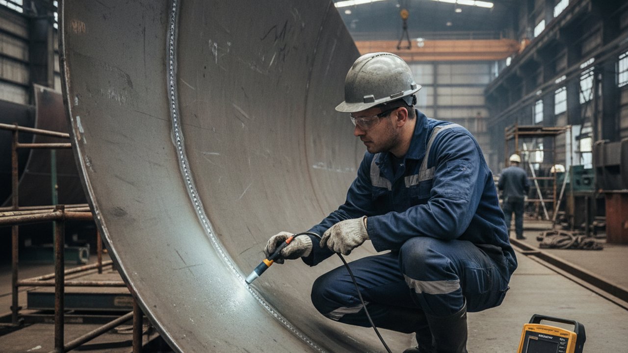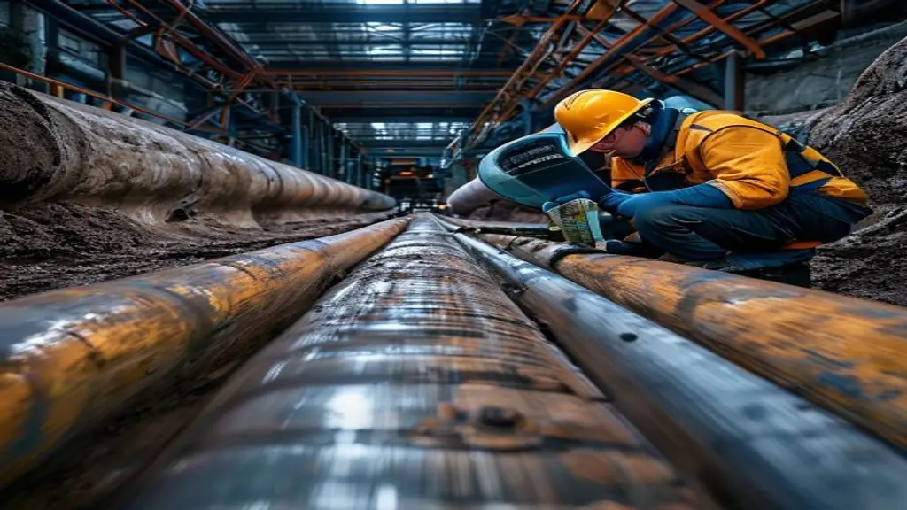
Long-distance pipelines move energy under thousands of pressure cycles per year, and the girth welds that join their joints are where the welding quality of the whole line is decided. API 1104 — the American Petroleum Institute’s “Welding of Pipelines and Related Facilities” — is the standard that defines how those welds must be made, qualified and inspected. Unlike ASME Section IX, which only qualifies procedures and welders, API 1104 also sets the acceptance standards for production welds, and it offers an alternative fracture-mechanics route (Annex A) that lets the company replace the workmanship limits with limits based on imperfection height as well as length. This guide walks through the inspection methods that API 1104 recognises, how the acceptance limits that drive most pass/fail calls in the field are built, and the practical evidence package an inspector should demand before signing a girth-weld report.
API 1104 at a glance: what the pipeline welding standard requires
The short answers, checked against the 22nd edition (July 2021), the current edition on API’s standards list in October 2026, with Errata 1 and Addendum 1 (the addendum published September 2026). Clause numbers below are those of the 22nd edition; a copy of the 21st edition, which US federal pipeline rules still cite, may number some clauses differently.
| Question | Short answer | Where in the 22nd edition |
|---|---|---|
| What does it cover? | Gas and arc welding used in the construction and in-service repair of carbon and low-alloy steel pipes and components for the compression, pumping and pipeline transmission of crude oil, petroleum products, fuel gases, carbon dioxide and nitrogen. | Section 1 |
| Which edition applies to my job? | The current one is the 22nd. 49 CFR Parts 192 and 195 incorporate the 21st edition (2013) by reference, so the contract and the regulator decide which edition binds the work. | API standards list; 49 CFR 192.7 and 195.3 |
| How are procedures and welders qualified? | A procedure is qualified with a test weld and tensile, nick-break and bend specimens, within the essential variables of Table 1. A welder is qualified by destructive tests or, at the company’s option for butt welds, by nondestructive testing (radiography or automated ultrasonic testing). | Section 5 (procedures), Section 6 (welders) |
| Which test methods have acceptance standards? | Radiography, magnetic particle testing, liquid penetrant testing and ultrasonic testing, including automated UT, plus visual limits for undercut. The test procedures themselves are in Section 11. | Section 9 (9.3 RT, 9.4 MT, 9.5 PT, plus UT criteria); Section 11 (11.1 RT, 11.4 UT) |
| What are the acceptance criteria? | Workmanship limits per imperfection type, measured on individual length, aggregate length in any continuous 12 in. (300 mm) of weld, width or image density. Cracks are defects except shallow crater or star cracks within a small length limit. The 22nd edition no longer has a separate cluster-porosity criterion. | Section 9 |
| How are repairs controlled? | Crack repairs need company authorization, and the company controls the other repairs. Qualified repair procedures by repair type (full-thickness, internal or external partial-thickness, cover pass, back weld, and double repairs), within the essential variables of Tables 1 and 9. The repaired weld must meet Section 9 again. | Section 10 |
| When can I use the ECA route? | At the company’s option, Annex A replaces the Section 9 limits with fracture-mechanics limits. It needs extra procedure tests (CTOD and Charpy toughness), a stress analysis and an inspection that sizes imperfection height. | Annex A |
| What about welding on a line in service? | Annex B covers in-service welding: procedures and welders qualified for welding onto a pipeline that is carrying product. | Annex B |
The rest of this guide expands the scope, the methods, the acceptance criteria, Annex A and repairs, then covers the part API 1104 does not control: what happens while each weld is being made.
Scope: what API 1104 covers and what it does not
API 1104 covers gas and arc welding of butt, fillet and branch welds in carbon and low-alloy steel piping used to compress, pump and transmit crude oil, petroleum products, fuel gases, carbon dioxide and nitrogen, both in new construction and in in-service welding. It is not a pressure vessel code or a plant piping code: those welds fall under ASME Section VIII and ASME B31.3. Special services such as sour service or hydrogen are normally handled by project specifications that add requirements on top of API 1104.
Two acceptance regimes co-exist in the standard:
- Workmanship criteria (Section 9) — empirical limits that give primary importance to imperfection length: individual length, aggregate length in any continuous 12 in. (300 mm) of weld, and width. Used by default and on most cross-country jobs.
- Alternative criteria (Annex A) — fitness-for-purpose limits from fracture mechanics, which weigh imperfection height as well as length. Used only at the company’s option and only when the additional procedure qualification tests, stress analysis and inspection required by Annex A are in place.
A girth weld inspector must know which regime applies before opening a film envelope or AUT scan, because the limits are built on different quantities and are not interchangeable.
Inspection methods recognised by API 1104
Section 9 of API 1104 sets acceptance standards for radiographic testing (RT), magnetic particle testing (MT), liquid penetrant testing (PT) and ultrasonic testing (UT), plus visual and mechanical limits for undercut. Section 11 gives the test procedures, including automated ultrasonic testing (AUT) with phased-array or time-of-flight diffraction techniques. Each method has a defined acceptance scope and qualification path.
Visual examination
Every welder qualification test weld is examined visually first: it must be free of cracks, inadequate penetration and burn-through, present a neat workmanlike appearance, and keep undercut within the limits the standard sets. On production welds, API 1104 gives visual and mechanical depth limits for undercut adjacent to the cover or root bead; when both mechanical and radiographic measurements are available, the mechanical one governs. Alignment of abutting pipe ends (Section 7) caps the offset for pipe of the same nominal wall thickness, and allows a larger offset only when it comes from pipe-end tolerances spread evenly around the circumference.
Radiographic testing (RT)
RT is the historical workhorse for pipeline girth welds and is still the default acceptance medium on many onshore projects. Section 11.1 sets the radiographic procedure, image quality indicators and both film and digital imaging. Acceptance limits in 9.3 are length- and width-driven: for example, on pipe of 2.375 in. (60.3 mm) outside diameter or more, more than four isolated slag inclusions up to 1/8 in. (3 mm) wide in any continuous 12 in. (300 mm) of weld is a defect (9.3.8.2). Porosity is judged on individual pore size against wall thickness and on distribution charts (9.3.9). The 22nd edition dropped the separate cluster-porosity criterion that earlier editions had, and 9.3.9.3 now covers hollow-bead porosity.
Automated ultrasonic testing (AUT)
AUT — phased array, often combined with TOFD — is the usual choice when running ECA per Annex A, because Annex A needs a technique that measures imperfection height with known accuracy. AUT advantages over RT include height sizing of planar flaws (incomplete fusion at the bevel, sidewall lack of fusion), results available during production, and no radiation exclusion zone. Disadvantages: AUT requires a procedure qualified on reference reflectors of known geometry and depth, and operators trained on that procedure.
Magnetic particle and penetrant testing
MT and PT are surface methods used as supplements, typically for branch connections, repairs, and the visible portion of root welds before cap deposition. They are not substitutes for volumetric inspection.
See the bevel while the weld is going down
Many Section 9 rejects form in seconds at the bevel. A welding camera shows the molten pool through the arc glare, frame by frame, so a suspect bead is spotted during welding — not at the AUT scan.
Book a girth-weld demo See the welding camera systemWorkmanship acceptance criteria — the table that drives the field
Section 9 of API 1104 contains the workmanship acceptance standards. The table below shows what each limit is measured on, not the limit values: read the values in the edition your contract cites, because some of them changed between editions.
| Imperfection | What the Section 9 limit is measured on |
|---|---|
| Cracks (C) | Any crack is a defect, except a shallow crater crack or star crack within a small length limit |
| Inadequate penetration without high-low (IP) | Individual length; aggregate length in any continuous 12 in. (300 mm) of weld; for shorter welds, a percentage of the weld length |
| Inadequate penetration due to high-low (IPD) | Individual length; aggregate length in 12 in. (300 mm), with more allowance than IP |
| Incomplete fusion (IF), open to the surface | Individual length; aggregate length in 12 in. (300 mm); for shorter welds, a percentage of the weld length |
| Incomplete fusion due to cold lap (IFD) | Individual length; aggregate length in 12 in. (300 mm) and as a percentage of the weld length |
| Internal concavity (IC) | Any length, as long as the image is no darker than the thinnest adjacent pipe wall; darker areas are judged as burn-through |
| Burn-through (BT) | Maximum dimension and image density against the thinnest adjacent pipe wall; sum of dimensions in 12 in. (300 mm) |
| Slag inclusions, elongated (ESI) | Length, aggregate length in 12 in. (300 mm) and width |
| Slag inclusions, isolated (ISI) | Aggregate length in 12 in. (300 mm), width, and number of indications (9.3.8.2) |
| Porosity (P) and hollow bead (HB) | Individual pore size against a fixed size and a share of wall thickness; distribution charts; hollow-bead length (9.3.9) |
| Undercut (EU, IU) | Aggregate length in 12 in. (300 mm) and as a fraction of the weld length; visual and mechanical depth limits |
The table follows the radiographic criteria of 9.3; magnetic particle and liquid penetrant indications have their own criteria in 9.4 and 9.5. Ultrasonic indications are classified as linear, transverse or volumetric and judged mainly on length; limits based on imperfection height belong to Annex A.
Operating tip: in the field the most common pitfall is summing imperfections across the wrong gauge length. API 1104 evaluates aggregate lengths in any continuous 12 in. (300 mm) of weld, not over the whole 360° girth weld, and welds shorter than 12 in. have their own percentage rule. Summing over the whole circumference hides clusters of short indications that the 300 mm window would reject.
Annex A and the engineering critical assessment route
Annex A gives alternative acceptance standards for girth welds. The Section 9 limits are empirical and put primary weight on imperfection length; Annex A uses fracture mechanics and fitness-for-purpose criteria that weigh imperfection height as well, and can allow larger imperfections. Its use is entirely at the company’s option, and it never prevents Section 9 from being applied to any weld. The prerequisites are non-trivial:
- Welding procedure toughness. The welding procedure is qualified with additional fracture-toughness tests — CTOD and Charpy impact tests — on welds representative of production.
- Stress analysis. The company determines the axial design stresses and strains acting on the girth welds, including the residual stress from welding, and documents them.
- Height-sizing inspection. Imperfection length, height and depth below the surface must be measured by a technique whose accuracy has been established, with any inaccuracy counted conservatively. Conventional radiography measures length but not height, which is why AUT is the usual partner of Annex A.
Even under Annex A, transverse planar imperfections — those running across the girth weld — must be repaired or removed (A.5.1.6). Annex A tends to pay off where the extra testing and analysis are cheaper than the repairs the workmanship limits would trigger, and where AUT is already on the spread.
Welder and procedure qualification
API 1104 separates welding procedure specification (WPS) qualification (Section 5) from welder qualification (Section 6). A WPS is qualified by welding a test joint and testing specimens cut from it — tensile, nick-break and bend tests — and it stays valid only within the essential variables listed in Table 1; Annex A adds fracture-toughness tests when the alternative acceptance route is used. A welder is qualified by making a test weld with a qualified procedure, which is examined visually and then tested destructively (tensile, nick-break and bend specimens) or, at the company’s option for butt welds, by nondestructive testing — radiography or automated ultrasonic testing (6.6). Repair welders are qualified separately, by destructive testing on a repair made with the repair procedure.
Modern operators tie WPS, PQR, welder qualification certificates, NDT reports and consumable lot traceability into a single digital record per girth weld. Therness’s welding QMS software and digital welding quality records workflows show how an audit-ready package looks for an API 1104 spread. The pipeline monitoring hardware that feeds those records is what makes the capture automatic rather than manual.
Repairs and rework
Repairs are tightly controlled by Section 10. Cracks are repaired only with company authorization, a cracked weld that is not repaired is cut out, and the company decides how other defects are repaired. A qualified repair procedure is required in the cases Section 10 lists — for example when the repair uses a different process or filler metal from the original weld, and for every repair in a previously repaired area (a double repair). Repair procedures are qualified by repair type: full-thickness, internal or external partial-thickness, cover-pass and back-weld repairs, within the essential variables of Tables 1 and 9 (10.3.4). The repaired area is inspected again and must meet the acceptance standards of Section 9.
Audit check: a repair procedure qualified once and then reused for a repair type, location or essential variable it does not cover — for example a fusion-line excavation under a procedure qualified on a centerline excavation. Check every repair against the repair type and the essential variables of Tables 1 and 9, and check that the repair welder is qualified for that repair type.
What an audit-ready acceptance package looks like
Beyond the welds themselves, an API 1104 audit asks for an evidence trail per girth weld. A clean package contains:
- WPS and PQR covering the joint geometry, position, consumable and heat input range used.
- Welder qualification record valid for the position and direction of progression.
- Consumable certificates with lot traceability to the actual rod or wire used on the weld.
- Preheat and interpass temperature record (see ISO 13916 monitoring for the equivalent ISO method).
- NDT report (RT or AUT) with operator qualification certificates, calibration record and the acceptance regime applied (Section 9 vs Annex A).
- For Annex A: the ECA report, the AUT procedure qualification record and the project specification clause authorising Annex A use.
Organisations running large pipeline programs typically replace paper folders with a digital NCR and traceability layer. See the welding NCR management flow for how an NCR raised on a girth weld feeds the repair workflow without losing the inspector–welder–procedure linkage.
How real-time monitoring complements API 1104
API 1104 is an acceptance standard, not a process-control standard. It tells the inspector what an acceptable weld looks like after it has been made; it does not, by itself, prevent a girth weld from being deposited outside its qualified parameter window. A real-time weld monitoring system tracking arc current, voltage, travel speed, heat input and interpass temperature closes that loop: girth welds outside the qualified envelope can be flagged before NDT, root cause is captured at the time of deviation, and AUT scan time is concentrated on the welds that need it. A welding camera system extends that same loop to the weld itself: thermal imaging reads heat distribution through the arc while a high-speed visual camera resolves the molten pool, so undercut, burn-through and incomplete fusion are flagged and logged the moment they form on the bevel, well ahead of the AUT scan. On a spread where every repair means excavation, rewelding and a second inspection, finding the suspect weld while the crew is still on it is where monitoring pays back — the thermal-imaging weld comparison below shows how heat distribution alone separates a sound weld from a suspect one.

Monitoring during deposition and NDT after it are separate layers. Where a spread needs a volumetric look at tie-in welds without a radiation exclusion zone — a real constraint on live rights-of-way — an excitation-based thermal inspection route is worth evaluating as a complement to RT and AUT.
For the high-speed visual channel described above, see the PoolDrop 480 fps weld pool camera. To check whether a camera setup fits your spread and bevel access, request a welding camera system demo for girth welds.
Make your pipeline welds audit-ready in real time
Therness combines API 1104 / Annex A digital records with real-time arc and thermal monitoring so girth welds are caught at the source — not at the AUT scan.
Book a demo See welding camera systemsFrequently Asked Questions
What is API 1104?
API 1104 is the American Petroleum Institute standard "Welding of Pipelines and Related Facilities". It sets requirements for gas and arc welding used in the construction and in-service repair of carbon and low-alloy steel pipes and components for the compression, pumping and pipeline transmission of crude oil, petroleum products, fuel gases, carbon dioxide and nitrogen: procedure and welder qualification, production welding, inspection, acceptance standards for nondestructive testing and repairs.
How does API 1104 differ from ASME Section IX?
ASME Section IX qualifies welding procedures and welders for pressure vessels and for piping built to the ASME B31 codes; it does not set acceptance standards for production welds, which come from the construction code. API 1104 covers pipelines and does both: it qualifies procedures and welders, and its Section 9 sets workmanship acceptance standards for production girth welds, with Annex A as an alternative fracture-mechanics route that ASME IX does not provide.
When can I use API 1104 Annex A (alternative acceptance)?
Annex A is used at the company's option, in place of the Section 9 workmanship limits. It replaces length-based limits with limits from fracture mechanics, which weigh imperfection height as well as length. In return it requires additional procedure qualification tests (fracture toughness, including CTOD and Charpy impact tests), a stress analysis of the pipeline, and an inspection technique of proven accuracy for imperfection height, usually automated ultrasonic testing. Transverse planar imperfections must still be repaired or removed.
What defects are most often rejected on pipeline girth welds?
API 1104 does not publish rejection statistics: it sets the limits. The Section 9 limits leave little room for cracks, which are defects unless they are shallow crater or star cracks within a small length limit; for inadequate penetration without high-low and incomplete fusion open to the surface, which are capped both on individual length and on aggregate length in any 12 in. (300 mm) of weld; and for burn-through whose image is darker than the thinnest adjacent pipe wall. Which of these drives the rejection rate on a spread depends on the process, the position and the inspection method.
Which edition of API 1104 is current?
The 22nd edition, published by API in July 2021, with Errata 1 and Addendum 1 (the addendum published September 2026). US federal pipeline safety regulations (49 CFR Parts 192 and 195) still incorporate the 21st edition of 2013 by reference, so the contract and the regulator decide which edition binds a given job, and clause numbers differ between editions.