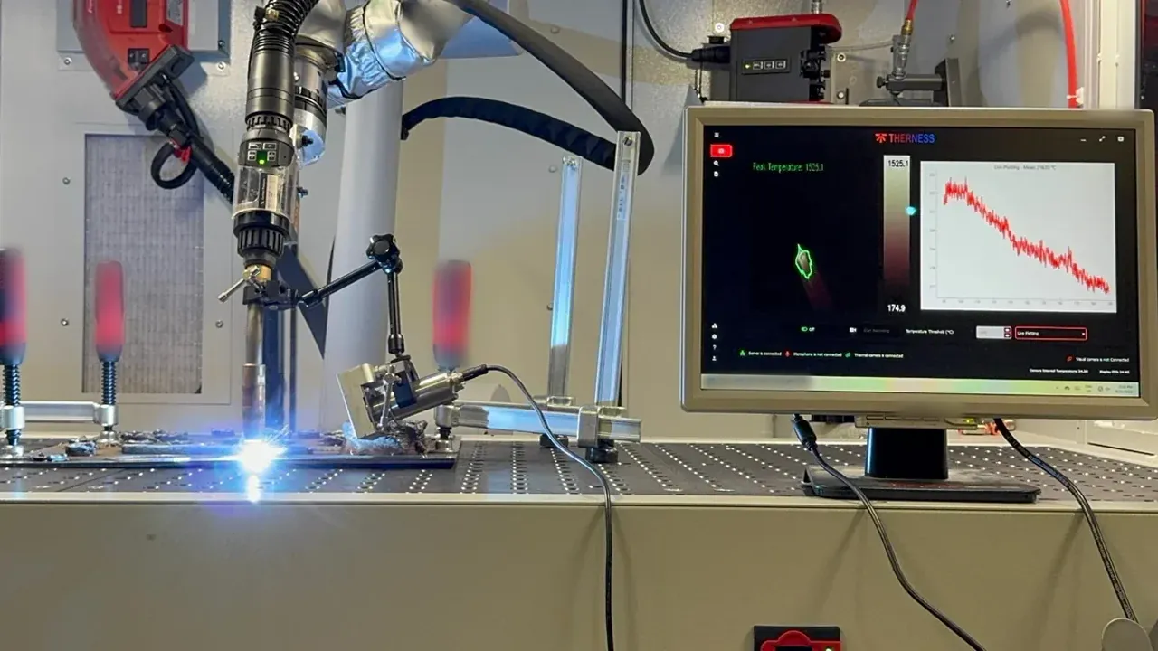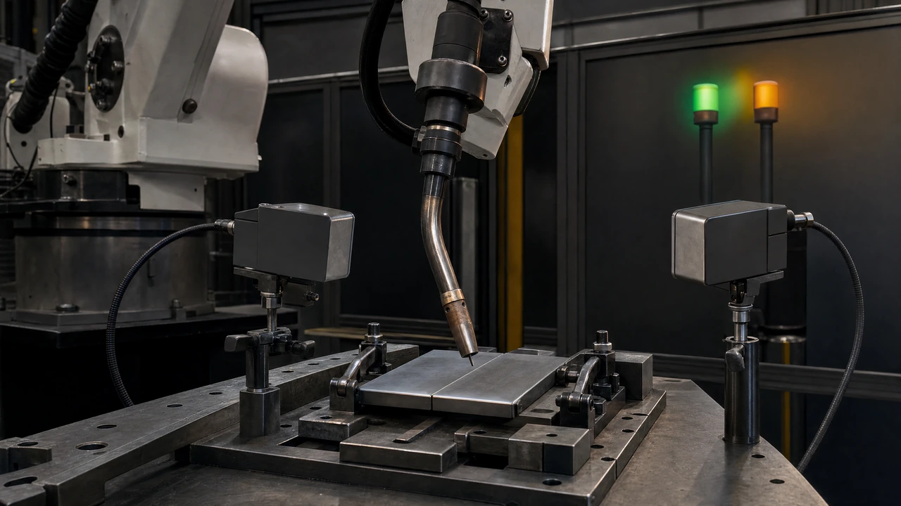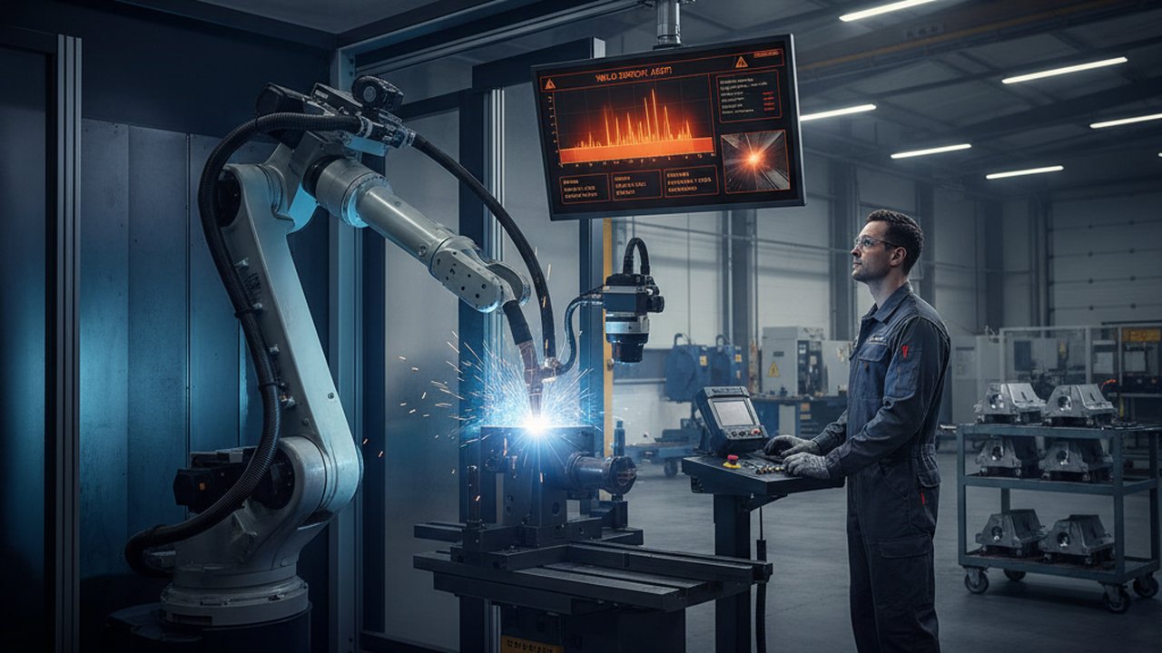
Real-time weld defect alerts turn a monitoring feed into an action the moment a parameter or defect signature crosses a threshold, instead of waiting for a batch review or a final inspection that happens hours after the arc goes out. Most welding cells already collect enough data to do this — current, voltage, travel speed, a thermal camera on the pool, an acoustic sensor on the torch — but very few plants have turned that data stream into a working alert-and-response system. The gap is almost never the sensor. It is the threshold logic, the escalation path, and the discipline to keep alarms meaningful instead of letting them decay into noise.
That gap matters because an alert nobody trusts is worse than no alert at all. An operator who gets ignored by a system that fires on every minor excursion learns, correctly, to stop looking at it — and the one time the alert is right, it gets dismissed with the rest. Building a real-time weld defect alert system that people actually act on requires the same rigor as building the welding process itself: defined thresholds tied to real data, a response workflow with owners and timers, and a verification loop that proves the alarms still mean something six months after they were configured.
Key takeaways
- Real-time weld defect alerts catch a defect while it is still forming or immediately after, instead of relying on a final inspection to find it once the part has moved downstream.
- Alarm thresholds need at least two severity tiers and process-capability data behind them, or the system trains operators to ignore alerts (alarm fatigue).
- A weld alert without a defined escalation path is just a notification — it needs an acknowledgment window and an automatic next-responder if that window is missed.
- Every alert should log timestamp, parameter or defect type, threshold crossed, part ID, acknowledgment, and disposition, or the alert history is not audit-usable.
- Real-time alerting directly improves PFMEA detection scoring and strengthens the evidence behind an ISO 3834-2 process-control claim.
- SPC (Cpk/Ppk) trend data and real-time alerts should share the same threshold logic, not be maintained as two disconnected systems.
- A weld defect alert system that fires constantly on marginal excursions gets tuned out faster than a system with no alerts at all.
Table of Contents
- What Is a Real-Time Weld Defect Alert System?
- Setting Alarm Thresholds Without Causing Alarm Fatigue
- Step-by-Step: Building the Alert and Escalation Workflow
- Common Alerting Failure Modes — and How to Fix Them
- Validating and Verifying a Weld Defect Alert System
- Connecting Alerts to PFMEA, SPC, and Weld Monitoring Standards
- Frequently Asked Questions
An alert system is only as credible as its false-alarm rate. Before adding a new threshold, plants get more value from tuning the thresholds they already have than from adding another sensor feed nobody trusts.
What Is a Real-Time Weld Defect Alert System?
A real-time weld defect alert system watches a welding process while it runs and pushes a notification the instant a monitored value crosses a defined limit, rather than surfacing the issue on a shift report or a sampled audit. The monitored value can be a raw process parameter (current, voltage, wire feed speed, travel speed, preheat/interpass temperature) or a derived defect signature from a live weld camera or thermal monitoring feed — a cold spot suggesting lack of fusion, a pool geometry excursion suggesting excessive penetration, or a spatter pattern suggesting contamination.
The distinction that matters operationally is between a process alarm and a detection alarm. A process alarm fires when a parameter drifts outside its normal operating window — current running high, travel speed too fast — before that drift has necessarily produced a defect. It is preventive: the operator can often correct the process before any weld metal is affected. A detection alarm fires on evidence that a specific defect has likely already formed, such as a thermal signature consistent with lack of fusion. It confirms a probable nonconformance that needs disposition, not just a parameter correction. A mature real-time weld defect alert system runs both types in parallel, because they answer different questions: “is the process still capable?” and “did this specific weld pass?”
Setting Alarm Thresholds Without Causing Alarm Fatigue
Alarm fatigue is the single most common reason real-time monitoring programs quietly stop being used. It happens when thresholds are set conservatively “to be safe,” the system fires dozens of times a shift, and operators learn that most alerts do not correspond to a real problem. The fix is not fewer sensors — it is fewer, better-calibrated alarms with a severity structure operators can actually act on, an approach adapted from the alarm-management discipline used in process safety management programs across other process industries.
| Tier | Trigger condition | Typical response time | Who acts |
|---|---|---|---|
| Tier 1 — Informational | Parameter approaching, but not past, its control limit | No immediate action; logged for trend review | System / SPC review |
| Tier 2 — Process alarm | Parameter outside its statistically derived control limit | Minutes — operator adjusts or pauses | Operator |
| Tier 3 — Detection alarm | Defect signature consistent with a known failure mode | Immediate — stop and disposition | Operator, then supervisor |
| Tier 4 — Critical/safety-relevant | Severity-9/10 failure mode per the process PFMEA | Immediate stop, no exceptions | Supervisor / quality engineer |
Two rules make this table work in practice. First, set the Tier 2 control limits from real Cpk/Ppk process-capability tracking on the specific parameter for the specific joint, not from a generic vendor default — a limit copied from a different material or thickness will either fire constantly or never fire. Second, tie the acceptance basis for Tier 3 detection alarms to the same quality-level table used for final inspection, such as ISO 5817:2023, so an in-process alert and a post-weld inspection reject the same defect for the same reason instead of using two different definitions of “bad.”
Teams often set every alarm to the same severity because it is simpler to configure. That collapses the tier structure and forces the operator to treat a minor excursion with the same urgency as a critical one — which is exactly the pattern that produces alarm fatigue within a few weeks.
Step-by-Step: Building the Alert and Escalation Workflow
- Inventory the monitored parameters and defect signatures. List every process parameter and every camera- or sensor-derived defect signature currently available, and map each to the failure mode it is meant to catch.
- Pull process-capability and nonconformance data. Before setting a single threshold, gather at least several weeks of production data for the parameter and cross-reference it against known scrap and rework events.
- Assign a severity tier to each alarm. Use the four-tier structure above (or an equivalent) so operators can distinguish “worth noting” from “stop now.”
- Define the acknowledgment window per tier. Tier 2 might allow five minutes before escalating; Tier 4 should escalate immediately if the line does not stop.
- Define the escalation chain. Name the specific role — not just “quality” — that receives an unacknowledged alert at each tier, and confirm they can actually act on it (authority to stop the line, access to disposition the part).
- Route alerts to where people already work. A system that only shows alerts on a dashboard nobody watches performs no better than no system; route to the HMI, a floor display, or a messaging channel the shift actually uses.
- Log every alert with disposition. Timestamp, parameter or defect type, threshold value, part/work-order ID, who acknowledged it, and what action was taken.
- Pilot on one cell before rolling out plant-wide. Run the tier structure on a single line for two to four weeks and tune thresholds against real false-alarm and miss rates before expanding.
- Review threshold performance on a fixed cadence. Monthly or quarterly, recalculate control limits against updated process-capability data and retire or tighten thresholds that no longer earn their alerts.
Common Alerting Failure Modes — and How to Fix Them
| Alerting failure | Why it happens | Fix |
|---|---|---|
| Every alarm treated as equally urgent | No tier structure was designed in | Apply a severity model and enforce different response times per tier |
| Thresholds copied from a different process or vendor default | Faster to configure than pulling real data | Derive control limits from this process’s own Cpk/Ppk history |
| Alerts sent to a dashboard nobody monitors | Alerting treated as a reporting feature, not an operational one | Route to the channel the shift already uses, with an acknowledgment requirement |
| No escalation if the first responder is unavailable | Escalation chain never defined past the operator | Add a timed automatic escalation to a named backup role |
| Alert history has no disposition field | System logs the trigger but not the resolution | Require a closing action before an alert can be marked resolved |
| Thresholds never revisited after go-live | No owner assigned to periodic review | Assign threshold review to the same cadence as PFMEA and control-plan review |
Technical references on weld-specific failure modes, such as the American Welding Society’s guidance on weld defects and TWI’s technical knowledge base, are useful inputs when deciding which defect signatures deserve their own detection alarm versus which are adequately covered by a process alarm on the underlying parameter.
Validating and Verifying a Weld Defect Alert System
An alert system is only as trustworthy as the evidence that it catches what it claims to catch. Verification should check three things on a recurring basis, not just at commissioning.
First, confirm the false-alarm rate against real dispositions. Pull every Tier 2 and Tier 3 alert over a defined period and check what fraction actually corresponded to a scrapped, reworked, or flagged part. A tier with a false-alarm rate above roughly 20-30% is a strong candidate for threshold tightening or removal.
Second, confirm the miss rate against final inspection. Cross-reference parts rejected at final inspection or NDT against the alert log for that part. A defect that reaches final inspection with no corresponding in-process alert means either a threshold is set too loosely or a failure mode has no monitored signature at all — both are gaps the process FMEA should already be tracking.
Third, confirm sensor and camera calibration. An alert is only as good as the signal behind it; periodic calibration and verification of the underlying monitoring system is what keeps a threshold meaningful over time instead of drifting quietly out of specification. Personnel performing that verification, particularly where it overlaps with NDT-based confirmation of a flagged weld, should hold the qualification defined in ISO 9712 for the method in use. Independent published research on in-process weld monitoring, such as work indexed in the Journal of Materials Processing Technology, is a useful cross-check against vendor claims when evaluating a new detection signature before it goes into production.
Connecting Alerts to PFMEA, SPC, and Weld Monitoring Standards
Real-time alerting is not a standalone tool — it is the operational expression of decisions already made in the PFMEA, the control plan, and the SPC program, and it should be built to reinforce all three rather than run in parallel with them. Detection scoring in a welding PFMEA improves directly when a failure mode has a working in-process alert behind it, because the control catches the defect before more value is added or the part moves downstream. The same threshold logic that drives SPC control charts for welding should set the Tier 2 process-alarm limits described above; maintaining two separate threshold definitions for the same parameter is a common and avoidable source of conflicting signals on the floor.
On the standards side, ISO 3834-2 requires documented process control appropriate to its comprehensive quality level, and a working alert-and-escalation workflow is one of the more defensible ways to demonstrate that requirement with evidence rather than a procedure binder. Platforms such as Therness HeatCore AI are built to generate exactly that evidence — tiered, logged, escalating alerts tied to real thermal and process data — as part of a broader welding monitoring system rather than a single-purpose alarm add-on. For codes and standards bodies referenced across this framework, see ASME’s codes and standards program, NIST’s manufacturing resources on process control and Industry 4.0 data practices, ASQ for the underlying SPC and control-chart methodology, and AIAG’s quality resources for how control plans and FMEA connect in automotive-driven supply chains. Teams standardizing alerting alongside PFMEA, control plans, and nonconformance tracking often move faster with AI-assisted QMS tooling that keeps those documents linked instead of drifting apart, and plants weighing where alert data should ultimately live can pair this with a weld data historian and MES integration so the alert log and the production record are the same record, not two.
Frequently Asked Questions
What is a real-time weld defect alert system?
A real-time weld defect alert system monitors weld parameters, thermal signature, or vision data during welding and triggers a notification the moment a reading crosses a defined threshold, rather than waiting for a finished-part inspection. It pairs an in-process sensor or camera feed with alarm logic that routes the alert to the operator, supervisor, or quality system for a defined response.
How do you set alarm thresholds for weld monitoring without causing alarm fatigue?
Base thresholds on process-capability data (Cpk/Ppk) and historical nonconformance records rather than arbitrary limits, use at least two severity tiers so only the most serious excursions interrupt an operator, and review threshold performance on a fixed cadence to remove alarms that fire often but rarely correspond to a real defect.
What is the difference between a detection alarm and a process alarm in welding?
A process alarm flags a parameter drifting outside its normal operating window before it necessarily produces a defect. A detection alarm flags evidence that a specific defect has likely already occurred. Process alarms are preventive; detection alarms confirm a probable nonconformance that needs disposition.
Who should receive a weld defect alert, and how fast should they respond?
The operator running the cell should receive the first-tier alert with a defined response time, typically under a few minutes. Unacknowledged or high-severity alerts should escalate automatically to a supervisor or quality engineer on a fixed timer, so a missed notification does not silently become a shipped defect.
Does ISO 3834 require real-time alerting for welding processes?
ISO 3834-2 does not name real-time alerting by number, but it requires documented process control and monitoring appropriate to the comprehensive quality level it specifies. In-process alerting is one of the most direct ways to demonstrate that control requirement is met with evidence rather than a procedure that exists only on paper.
How does alarm escalation work when the first responder does not act?
Escalation logic defines a maximum acknowledgment window for each alarm tier. If the assigned first responder has not acknowledged the alert within that window, the system automatically notifies the next role in the chain and logs the delay so unresponsive escalation paths can be identified and fixed.
What data should a weld defect alert log for traceability?
Each alert should log the timestamp, the parameter or defect type that triggered it, the threshold value crossed, the part or work-order identifier, who acknowledged it and when, and the disposition action taken. That record is what turns an alert history into evidence an auditor or customer can trust.
Can real-time weld alerts reduce scrap and rework costs?
Yes, because catching a defect while the weld is still being made, or immediately after, avoids the cost of welding additional passes onto a joint that will be rejected, and avoids the labor of moving a bad part through downstream stations before it is caught at final inspection. The savings scale with how many process steps follow the welding operation.
Building a real-time weld defect alert workflow?
We help welding and quality teams turn monitoring data into tiered alerts, escalation paths, and audit-ready evidence tied to PFMEA and SPC.
Book a monitoring consultationTherness solution: Welding monitoring system — Every weld inspected in the cycle, with defect flags and the ISO 3834 / ISO 17635 evidence kept per weld.
Frequently Asked Questions
What is a real-time weld defect alert system?
A real-time weld defect alert system monitors weld parameters, thermal signature, or vision data during welding and triggers a notification the moment a reading crosses a defined threshold, rather than waiting for a finished-part inspection. It pairs an in-process sensor or camera feed with alarm logic that routes the alert to the operator, supervisor, or quality system for a defined response.
How do you set alarm thresholds for weld monitoring without causing alarm fatigue?
Base thresholds on process-capability data (Cpk/Ppk) and historical nonconformance records rather than arbitrary limits, use at least two severity tiers so only the most serious excursions interrupt an operator, and review threshold performance on a fixed cadence to remove alarms that fire often but rarely correspond to a real defect.
What is the difference between a detection alarm and a process alarm in welding?
A process alarm flags a parameter drifting outside its normal operating window, such as current or travel speed, before it necessarily produces a defect. A detection alarm flags evidence that a specific defect, such as lack of fusion or excessive porosity, has likely already occurred. Process alarms are preventive; detection alarms confirm a probable nonconformance that needs disposition.
Who should receive a weld defect alert, and how fast should they respond?
The operator running the cell should receive the first-tier alert with a defined response time, typically under a few minutes, since they can intervene immediately. Unacknowledged or high-severity alerts should escalate automatically to a supervisor or quality engineer on a fixed timer, so a missed notification does not silently become a shipped defect.
Does ISO 3834 require real-time alerting for welding processes?
ISO 3834-2 does not name real-time alerting by number, but it requires documented process control and monitoring appropriate to the comprehensive quality level it specifies. In-process alerting is one of the most direct ways to demonstrate that control requirement is met with evidence rather than a procedure that exists only on paper.
How does alarm escalation work when the first responder does not act?
Escalation logic defines a maximum acknowledgment window for each alarm tier. If the assigned first responder has not acknowledged the alert within that window, the system automatically notifies the next role in the chain, typically a shift supervisor, and logs the delay so unresponsive escalation paths can be identified and fixed.
What data should a weld defect alert log for traceability?
Each alert should log the timestamp, the parameter or defect type that triggered it, the threshold value crossed, the part or work-order identifier, who acknowledged it and when, and the disposition action taken. That record is what turns an alert history into evidence an auditor or customer can trust.
Can real-time weld alerts reduce scrap and rework costs?
Yes, because catching a defect while the weld is still being made, or immediately after, avoids the cost of welding additional passes onto a joint that will be rejected, and avoids the labor of moving a bad part through downstream stations before it is caught at final inspection. The savings scale with how many process steps follow the welding operation.