Interpass temperature in welding is the temperature of a multi-run weld and the adjacent parent metal immediately before the next run starts. That definition comes from ISO 13916:2025, Clause 3.2. The production limit does not come from a generic material chart: it comes from the approved Welding Procedure Specification (WPS) and its governing qualification and contract documents.
This guide separates those two decisions: first find the permitted range in the controlled WPS, then measure at the point and time defined by the applicable procedure. It does not reproduce standard limits or substitute a typical value for a qualified one.
Interpass Temperature in Welding: Quick Answer
Before each subsequent run, measure the weld metal or immediately adjacent parent metal at the location defined by the WPS or inspection plan. Take the reading immediately before arc start. Compare it with the minimum, maximum, or bounded range in the current WPS; if it is outside that range, hold the next run until the approved disposition is completed.
Use the interpass temperature definition for the term, the ISO 13916 scope card for the measurement decision, and the interpass temperature timer when a local, browser-based timestamped log fits the job. The tool does not choose the limits: the operator enters the values from the WPS.
What Is Interpass Temperature?
In multi-pass welding, interpass temperature (Ti) is a condition of the weld area, not a machine setting. ISO 13916:2025 distinguishes it from preheating temperature and preheat-maintenance temperature, and its scope expressly excludes post-weld heat-treatment temperature measurement.
A WPS can state a minimum, a maximum, or both. Read the actual range and revision from the controlled WPS rather than inferring it from an alloy family. See automatic cooling-time analysis for a separate example of tracking thermal decay between passes; cooling time and interpass temperature are related measurements, not interchangeable records.
Interpass Temperature Limits by Material Group
Material group is an input to procedure selection; it is not enough to establish an interpass limit. For carbon and low-alloy steel, stainless steel, duplex grades, nickel alloys, or aluminium, use the same document path:
- identify the material designation and group on the drawing, material certificate, and WPS;
- confirm the application standard, contract supplement, and approved WPS revision that govern the joint;
- read the permitted interpass range from that WPS and trace it to the supporting WPQR or PQR;
- check whether a repair, dissimilar joint, process change, or heat-treatment condition invokes a different procedure.
ISO 15614-1:2017 covers procedure qualification by welding procedure tests for its stated steel and nickel-alloy scope. For work qualified under that document, read Clause 8.4.9 in the purchased standard and verify the level-specific requalification boundary, material-group conditions, and stated exceptions. Do not transfer that clause to aluminium or to work governed by another code without checking the applicable document.
Clause pointer, not a limit: ISO 15614-1 Clause 8.4.9 addresses interpass temperature within the range of qualification. Look up the rule and its conditions in the edition invoked by the contract. Record the WPS value actually used on the job; do not copy a number from this article or another project.
Measurement Methods in Practice
ISO 13916:2025 Clause 4.3 states that the equipment should be specified in the WPS and identifies temperature-sensitive materials, contact thermometers, thermocouples, and optical or electrical devices for contactless measurement. Method selection must follow the joint, access, surface, uncertainty, and record requirements of the approved procedure.
Contact Thermometers (Thermocouple Probes)
A contact thermometer or thermocouple produces a reading at the point where the sensor contacts the workpiece. Use the sensor type, contact preparation, response time, and instrument status defined by the WPS or measurement procedure. The measurement location for interpass temperature is addressed separately in ISO 13916:2025 Clause 4.1; the preheat-distance geometry in that clause must not be copied onto the interpass check.
Record the method and instrument identity with the reading when the project requires traceability. A point reading represents that point only, so the inspection plan must decide how many locations are needed for a long or thermally uneven joint.
Infrared Pyrometers (Spot Pyrometers)
These are contactless devices under ISO 13916:2025 Clause 4.3. They infer surface temperature from measured radiation. NIST explains that radiometric cameras and pyrometers depend on calibration and knowledge of surface emissivity; surface texture, viewing angle, and oxidation state can change the result.
Define and validate the emissivity method, field of view, viewing geometry, background treatment, and acceptable uncertainty for the real surface condition. A factory default emissivity value is not evidence that the production measurement is correct.
Thermal Imaging Cameras
A thermal camera applies the same radiometric constraints across an array of pixels. It can preserve a spatial frame around the specified measurement point, but a wider image does not by itself prove conformity: emissivity, optics, calibration, timing, point selection, and record linkage still require validation.
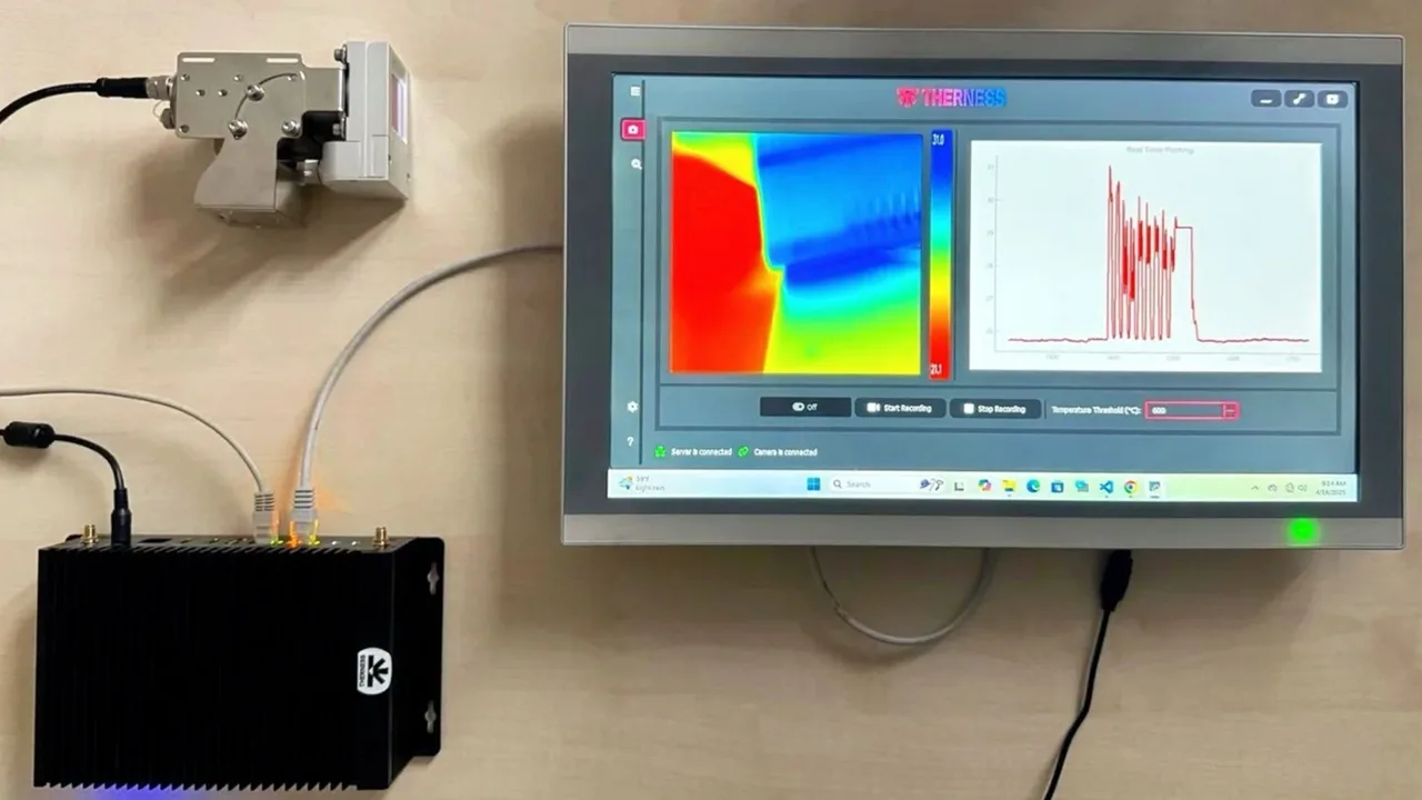
The HeatCam IR-C product page documents a fixed radiometric camera with PoE and Modbus connectivity. Whether it supports a production interpass record depends on the configured software, measurement method, and validation for that cell. The continuous weld monitoring system provides the wider system route. For implementation detail, see the guide to preheat and interpass temperature monitoring with thermal cameras.
Digital Contact Thermometers (Magnetic / Roller Type)
Magnetic holders and roller probes are contact-method implementations, not a separate permission to change the measurement point or timing. Confirm that the chosen sensor makes stable contact on the actual geometry, then document its response and verification method in the project procedure.
Measurement Point and Timing per ISO 13916
ISO 13916:2025 is the current edition. Use these clause pointers without turning them into a universal work instruction:
- Clause 4.1, point of measurement: for interpass temperature, check the weld metal or immediately adjacent parent metal. The distance geometry elsewhere in the clause concerns the preheating check; it is not the interpass location.
- Clause 4.2, time of measurement: take the interpass reading in the weld area immediately before the next layer is welded.
- Clause 4.3, equipment: specify the measurement equipment in the WPS.
- Clause 5, measurement records: look up when a record is required and the minimum content in the invoked edition, then add any joint, pass, instrument, and disposition fields required by the project.
- Clause 6, designation: use the applicable designation format when the project invokes it.
Project control checklist — not a reproduced standard checklist:
- Current WPS states the applicable minimum, maximum, or bounded range
- Measurement point and timing match the approved procedure
- Method, instrument identity, and required status evidence are recorded
- Reading resolves to the job, joint, and pass or layer
- An out-of-range reading blocks the next run until authorized disposition
Interpass Temperature in Welder Qualification Testing
ISO 9606-1:2012 qualifies a welder’s ability for manual and partly mechanized fusion welding of steels within its stated scope. It does not replace procedure qualification. When the test is performed to a specified WPS or pWPS, identify that document and the temperature controls actually used in the test record.
For a procedure qualified under ISO 15614-1, interpass temperature is addressed by Clause 8.4.9, not by ISO 9606-1. Before changing a production WPS, check that clause in the contractually invoked edition and confirm the applicable qualification level, material group, and exceptions against the WPQR. Do not infer a reusable numeric allowance from another job.
Documentation: What a Traceable Weld Record Must Contain
A useful production record should capture enough context to reproduce the decision. The following fields are project-control recommendations, not a verbatim list from ISO 13916:
- Ti reading (numeric value, not “OK” or a tick mark)
- Time of measurement
- Measurement method (contact / pyrometer / thermal camera)
- Instrument ID and the status reference required by the project
- WPS number and revision, welder ID, joint reference, and pass or layer ID
- Disposition when the reading is outside the WPS range
Do not backfill a reading from memory or replace it with “OK.” If the project requires a record for every pass or layer, capture it at the decision point before the next run begins.
The HeatCam IR-S product page documents network and protocol options for logging and automation, data export, and synchronization with other systems. Those interfaces can support a timestamped workflow, but the project still has to configure the point, timing, emissivity method, record identity, and disposition logic. Review the Therness thermal camera range when choosing a fixed or embedded form factor.
For the separate electrical-and-travel calculation, see the welding heat input calculation guide. Heat input does not replace the measured interpass reading.
Common Control Failures and How to Prevent Them
| Failure mode | Why it fails | Control |
|---|---|---|
| Generic material value copied into the traveller | It bypasses the approved WPS and qualification basis | Resolve the exact WPS revision before work starts |
| Preheat distance used for the interpass reading | It confuses two locations in ISO 13916 Clause 4.1 | State the interpass point in the job instruction |
| Reading taken after an informal cooling wait | It no longer represents the condition immediately before the next run | Measure at the decision point and timestamp it |
| Contactless method used with an unvalidated surface model | Apparent temperature can shift with emissivity and viewing conditions | Validate the radiometric method on the production surface |
| One value copied across several runs | It cannot demonstrate the condition before each required run | Record each required check against pass or layer identity |
Summary
Interpass temperature is the weld-area temperature immediately before the next run. The WPS supplies the permitted range; ISO 13916 supplies the measurement framework. A defensible record connects the actual reading to the correct point, time, method, instrument, WPS revision, joint, and pass or layer.
Start by removing generic material limits from uncontrolled shop instructions. Replace them with a controlled reference to the approved WPS, then verify the measurement workflow at the real joint before production release.
Plan interpass temperature evidence around your WPS
Therness can help scope a radiometric measurement and record workflow for your actual joint, surface, cell, and approved procedure. Review monitoring approaches for fixed welding cells before selecting the camera and software route.
Request an application reviewTherness solution: Welding monitoring system — Every weld inspected in the cycle, with defect flags and the ISO 3834 / ISO 17635 evidence kept per weld.