A WAAM monitoring camera turns each deposited layer from a black-box process event into a spatially-indexed, timestamped quality record. Wire Arc Additive Manufacturing builds near-net-shape metal components by depositing bead-by-bead from wire feedstock using a standard arc process — typically GMAW, GTAW, or plasma arc — guided by a robot or gantry over a digital tool path. The deposition physics are identical to conventional welding, but the quality-assurance challenge is fundamentally different: you are monitoring a three-dimensional build that evolves layer by layer, in a thermal environment that changes continuously as the part gains mass and retains heat.
Getting the camera setup right — field of view, arc-light suppression, working distance, and data routing — determines whether the system produces actionable quality evidence or an archive of unusable, saturated frames. This guide covers every parameter you need to configure a welding camera for additive manufacturing before your WAAM cell goes into production monitoring. It complements the broader WAAM process monitoring approach that ties camera data into full-build quality control.
Key Takeaways
- WAAM pool oscillation frequencies are typically 20–50 Hz, lower than conventional GMAW; a minimum of 480 fps still provides comfortable detection margin above the Nyquist rate.
- Field of view must cover the full melt pool plus a 5–10 mm margin on each side; a 30–80 mm FOV at the deposition plane covers the full practical range of WAAM wire diameters and currents.
- Arc-light suppression — a narrow bandpass filter matched to a monochromatic illumination source — is mandatory; without it the camera produces saturated frames at every arc-on moment.
- Tool path correlation (tagging each frame with the motion controller X-Y-Z position) is the integration step that transforms camera output from a video file into a voxel-indexed quality map.
- Timestamped WAAM pool images linked to deposition coordinates satisfy ISO 3834-2 clause 7.4 electronic process record requirements.
- The most common installation failures are optical window contamination during the first ten build hours, illumination intensity drift over a build campaign, and missing synchronisation between the camera clock and the motion controller.
- Post-process NDT finds defects; in-process WAAM camera monitoring identifies the deposition moment and root cause — both are necessary for a complete quality chain.
Table of Contents
- Why WAAM Monitoring Differs From Conventional Welding
- Camera Types: Visual, Thermal and Combined Systems
- Field of View, Working Distance and Optical Configuration
- Step-by-Step WAAM Camera Integration Procedure
- Data Integration: Tool Path Correlation and MES Connectivity
- Quality Standards and Process Record Requirements
- Common Failure Modes and Fixes
- Validation Before Production
- FAQ
Why WAAM Monitoring Differs From Conventional Welding
In conventional arc welding, monitoring addresses a fixed two-dimensional seam with a known joint geometry, constant ambient temperature, and a single-pass or limited multi-pass thermal history. WAAM breaks all three assumptions simultaneously.
Evolving thermal boundary conditions. As the build height increases, the component retains more heat from previous layers. The interpass temperature — and therefore the effective heat input into each new bead — changes throughout the build. A monitoring system configured for layer 5 may see a significantly different pool size and oscillation behaviour by layer 30 on the same parameter set. This thermal drift must be accounted for in the alert thresholds. For a deeper treatment of interpass temperature control in multi-pass builds, see the guide to interpass temperature measurement and WPS compliance.
Three-dimensional path geometry. Tool paths in WAAM are G-code or robot programs, not fixed weld joints. The camera must follow the deposition head through curves, ramps, and contour passes, maintaining its optical relationship to the pool despite continuous motion in all three axes. This places mounting constraints on the system that conventional weld monitoring cameras do not face.
Closed-loop feedback requirements. WAAM processes can be controlled in closed loop on bead height, width, or pool temperature — all derived from in-process sensor data. A monitoring camera that only records is useful for audit; one that feeds back into the controller adds the capability to maintain dimensional tolerance across a long multi-hour build. TWI’s WAAM technology overview describes the broader process landscape in which in-process sensing is becoming a standard component.
Quality evidence requirements. Regulatory frameworks for WAAM — including aerospace customer specifications, nuclear fabrication codes, and the emerging ISO/ASTM 52900 additive manufacturing standards — increasingly require process record evidence that each layer was deposited within specification. Camera data provides exactly this: a continuous, spatially-indexed record of the deposition event that cannot be reconstructed after the fact from post-process inspection alone. Cranfield University’s Welded Structures and Manufacturing group, which originated the WAAM process concept, has published extensively on the necessity of in-process monitoring to achieve consistent mechanical properties in production builds.
Camera Types: Visual, Thermal and Combined Systems
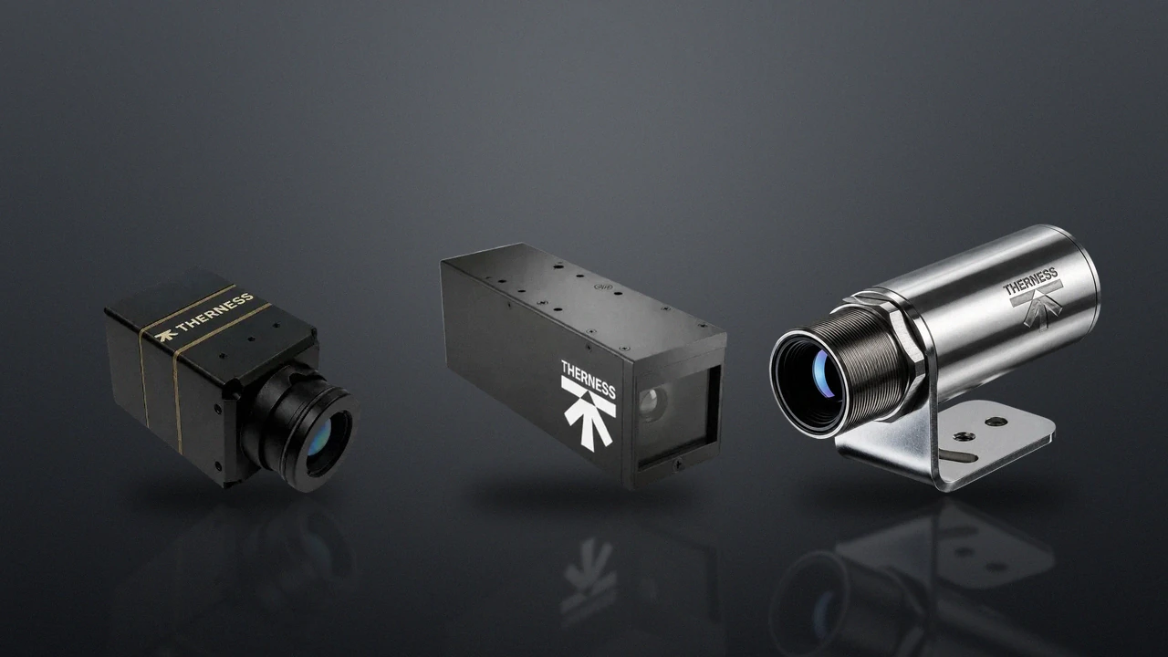
Three sensor modalities appear in WAAM quality monitoring. Selecting the right one — or the right combination — starts with defining which observable is most relevant to your process risk. Compare the full Therness camera and monitoring lineup across visual and thermal options.
High-speed visual cameras
A high-speed visual camera running at 480 fps or above resolves weld pool dynamics — oscillation frequency, pool cross-sectional geometry, spatter ejection, and arc stability events. These are leading indicators of defects: a pool oscillation anomaly precedes a lack-of-fusion event by several seconds; a spatter cluster precedes porosity nucleation. The camera requires arc-light suppression (bandpass filter and matched illumination) and does not carry temperature information.
LWIR thermal cameras
An LWIR thermal camera measures the temperature field around the deposition zone — including the isothermal bands used for interpass temperature control and post-bead cooling rate analysis. It operates without arc-light suppression because the arc emits below LWIR sensitivity (8–14 µm wavelength range). The Therness HeatCam — thermal monitoring in WAAM is designed for this application, providing temperature distribution data that integrates with heat input records and cooling rate calculations. For space-constrained or embedded WAAM cells, the compact HeatCam IR-S delivers the same LWIR record in a smaller envelope. An LWIR camera does not see pool geometry or arc dynamics.
Combined (visual + thermal) systems
Production WAAM cells in aerospace and nuclear applications increasingly run both sensor types in synchronised acquisition. The visual camera provides the pool geometry and arc quality record; the thermal camera provides the thermal record and interpass temperature compliance evidence. Combined systems require a data acquisition backbone that timestamps both streams against the motion controller position to enable spatial co-registration. Watch WAAM thermal monitoring in action to see the interpass record build layer by layer.
| Sensor type | Key observable | Arc suppression needed | Standards supported |
|---|---|---|---|
| High-speed visual | Pool geometry, oscillation, arc events | Yes — bandpass filter + matched illumination | ISO 3834-2 clause 7.4 |
| LWIR thermal | Temperature field, cooling rate, interpass temperature | No | ISO 3834-2 clause 7.4, EN 15085 CL1 |
| Combined | Full process record — geometry + thermal | Yes (visual channel) | ISO 3834-2, ISO/ASTM 52900, AWS D20.1 |
Field of View, Working Distance and Optical Configuration
The field of view (FOV) is the most consequential optical parameter in WAAM camera setup. Too wide, and the pool occupies too few pixels to resolve pool geometry changes — oscillation anomalies become noise below the detection threshold. Too narrow, and the camera misses pool-edge events relevant to bead width control.
FOV specification for WAAM
The FOV should cover the full melt pool plus 5–10 mm margin on each side. WAAM pool widths in GMAW-based processes range from approximately 3 mm (narrow wire, low current) to 12 mm (thick wire, high-current deposition for large structural parts). A FOV of 30–80 mm at the deposition plane covers this full practical range and provides enough spatial context to detect pool-edge irregularities, bead widening, or asymmetric solidification. Sensor resolution at this FOV should reach at least 0.05 mm per pixel to resolve pool geometry features at the detection threshold.

Working distance and mounting geometry
| Mounting style | Working distance | Advantages | Limitations |
|---|---|---|---|
| Coaxial (axis aligned with torch) | 80–150 mm from wire tip | Clean pool geometry data, no perspective distortion | Requires dedicated torch bracket; higher spatter impact risk on window |
| Off-axis 30–45° | 100–200 mm from pool surface | Easier retrofit to existing cells, angle adjustable | Perspective distortion requires calibration correction; partial pool shadow from torch body |
| Fixed standoff on robot flange | 150–250 mm from pool | Stable over long builds, no per-layer recalibration | FOV may clip bead on tall builds without programmed offset correction |
The working distance determines spatter impact energy on the protective optical window. Below 100 mm, spatter erosion of the window becomes the primary maintenance driver; above 200 mm, illumination flux density at the pool surface drops and exposure time must increase to compensate. The 120–160 mm range is the practical optimum for most GMAW-based WAAM.
For embedded and space-constrained deposition heads where none of the three mounting styles above leaves enough bracket clearance, a compact WAAM monitoring camera sized for tight integration is often the only practical option.
Arc-light suppression and illumination
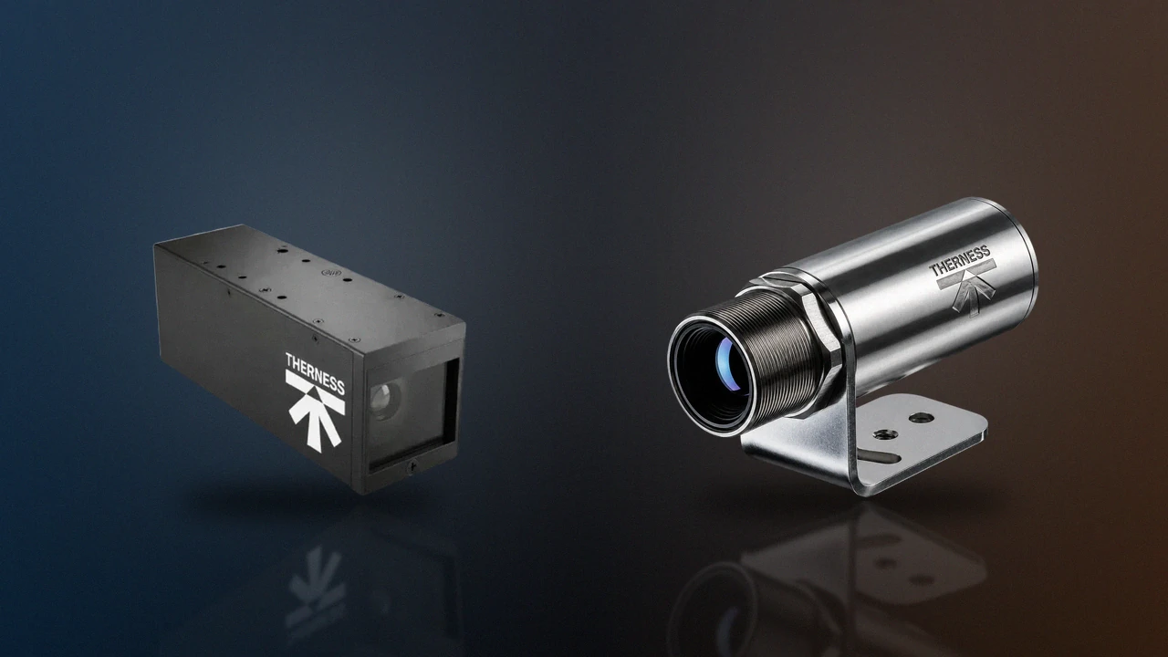
A WAAM monitoring camera requires a narrow bandpass filter (±10 nm) centred on the illumination wavelength, typically 808 nm or 905 nm. The filter must reach optical density 4 or higher outside the passband to prevent arc saturation. The Therness PoolDrop WAAM weld pool camera uses Class 1 laser-safe illumination (IEC 60825-1) matched to its bandpass filter, enabling installation in production bays without requiring personnel to wear laser-safety eyewear during normal operations. For a full treatment of arc glare suppression physics, see the arc glare and laser-safe illumination guide.
Always procure the bandpass filter and the illumination source together as a matched pair verified at the wavelength level. A filter centred at 808 nm paired with an 850 nm illumination source gives significantly reduced pool contrast, because the filter heavily attenuates the illumination outside its passband.
Step-by-Step WAAM Camera Integration Procedure
The following procedure assumes a GMAW-based WAAM cell with a six-axis robot or gantry, G-code toolpath, and a PC-based acquisition system.
Step 1 — Define monitoring objectives. Specify which observables you need: pool geometry only, thermal record only, or both. This decision drives sensor selection and data storage requirements. For ISO 3834-2 compliance, the minimum is timestamped pool geometry images linked to deposition coordinates.
Step 2 — Mount the camera. Fix the camera at the selected working distance (120–160 mm for coaxial, 150–200 mm for off-axis). Ensure the bracket is rigid — vibration during torch movement at WAAM travel speeds (200–600 mm/min) must not produce motion blur at the selected exposure time of 200–500 µs.
Step 3 — Install and align the optical window. A sapphire or hardened glass window protects the sensor from spatter. Align the window perpendicular to the optical axis to avoid image shift. Record the window serial number and installation date for maintenance tracking.
Step 4 — Calibrate the FOV. Place a calibration target (known grid pattern) at the deposition plane. Record the pixels-per-mm value and the optical centre coordinates. Store this calibration in the camera configuration file and reference it for every build.
Step 5 — Configure arc-light suppression. Install the bandpass filter, connect the illumination source, and verify filter–illumination wavelength match at the camera sensor. Capture a test image with the arc on and confirm no pixel saturation in the pool region.
Step 6 — Synchronise with the motion controller. Configure the acquisition system to receive the X-Y-Z position signal from the robot controller at the camera frame rate or at a defined interval — typically every 10 ms. This is the tool path correlation link described in §5 below.
Step 7 — Define monitoring thresholds. Run three to five qualification welds at nominal WPS parameters and record the pool geometry distribution: width mean and standard deviation, area mean and standard deviation, and oscillation frequency range. Set alert thresholds at ±2σ of the qualification distribution.
Step 8 — Validate and document. Perform the full validation procedure described in §8 before the first production build. Document the validation record with the camera configuration file version and attach it to the build quality file. For how the camera integration fits within the broader welding camera setup and integration framework, refer to the detailed specs guide for conventional arc welding — the same data architecture applies to WAAM with the addition of the spatial coordinate tag.
Data Integration: Tool Path Correlation and MES Connectivity
Camera data in isolation has limited value in WAAM. A pool geometry alert at frame 14,872 is actionable only if you know where in the build that frame was captured and what WPS parameter set was active at that moment.
Tool path correlation
Each camera frame is tagged with the current X-Y-Z position from the motion controller. The result is a frame-indexed dataset where every image carries a build coordinate. Post-build analysis maps pool geometry statistics onto the nominal CAD volume, identifying spatial clusters of anomalies that correspond to specific layers, contours, or geometric features. A cluster of oscillation anomalies at a particular height often corresponds to a transition in wall thickness or a change in heat sink geometry that was not reflected in the WPS.
The same spatial indexing approach used in welding digital twin and MES integration for conventional seam welding applies directly to WAAM, with the addition that the coordinate space is three-dimensional rather than along a linear seam.
MES and quality record structure
Camera data should be linked to the production order in the MES at the build level. The build record should contain:
- Camera configuration file version (FOV calibration, filter wavelength, illumination level, alert thresholds)
- Pool geometry statistics per layer — mean width, mean area, anomaly count and coordinates
- Thermal record reference if an LWIR camera was deployed
- Alert events with coordinates, frame references, and operator dispositions
This structured record satisfies the traceability requirements of ISO 3834-2 and aligns with the documentation expectations of the NIST additive manufacturing quality framework. For the audit checklist that maps camera monitoring data to ISO 3834 audit requirements, the spatial coordinate index is the element that distinguishes a compliant WAAM process record from a conventional welding record.
Quality Standards for WAAM Process Records
Several standards apply to WAAM monitoring camera data. Their requirements are complementary, not competing.
ISO 3834-2 (Comprehensive quality requirements for fusion welding of metallic materials): clause 7.4 requires documented evidence that process parameters were maintained within WPS limits throughout the weld. WAAM pool camera data — timestamped, spatially indexed, with defined and validated alert thresholds — satisfies this clause as an electronic in-process monitoring record.
ISO/ASTM 52900 (Additive manufacturing — General principles — Fundamentals and vocabulary): the foundational terminology standard for additive manufacturing. It establishes directed energy deposition (DED) as the category that covers WAAM. Familiarity with the DED classification is needed when writing the WAAM-specific sections of a supplier quality plan, because customer specifications increasingly reference the ISO/ASTM 52900 process category rather than the WAAM trade name.
AWS D20.1 (Specification for Fabrication of Metal Components using Additive Manufacturing): the AWS Foundation published D20.1 as the first US consensus standard for metallic AM fabrication. It includes process monitoring documentation requirements compatible with the camera monitoring approach described here, and it is increasingly cited by defence and nuclear OEM customer quality plans in North America.
ASME Additive Manufacturing Standards (ASME AM portfolio): ASME publishes a series of qualification and traceability standards for AM that address design, powder, and post-processing. For WAAM components entering pressure-containing applications, these standards establish the documentation baseline that in-process camera records contribute to.
EN 15085 (Railway welding): for WAAM parts entering rail applications, EN 15085 CL1 requires continuous process monitoring on the highest certification class joints. LWIR thermal monitoring satisfying EN 15085 rolling stock requirements is directly applicable to WAAM deposition on certified structural rail components.
Common Failure Modes and Fixes
| Failure mode | Root cause | Corrective action |
|---|---|---|
| Saturated (all-white) frames | Filter–illumination wavelength mismatch, or filter not installed | Verify filter centre wavelength against illumination datasheet; confirm OD ≥ 4 outside passband |
| Pool not visible in image | Illumination intensity insufficient at working distance | Increase illumination drive current within rated limits, or reduce working distance by 20 mm; recalibrate FOV |
| Image blur during torch movement | Camera exposure too long for WAAM travel speed | Reduce exposure to 200–300 µs; verify illumination intensity is still adequate at reduced exposure |
| Optical window fogging mid-build | Condensation during torch retract pauses on parts with high thermal mass | Add purge gas to the window housing; heat the housing above the process environment dewpoint |
| Optical window spatter erosion (first 10 h) | Working distance below 100 mm, or standard glass window used | Replace with sapphire window; increase working distance to 140 mm or above |
| Frame–position desynchronisation | Acquisition PC clock not synchronised with motion controller | Use hardware trigger from motion controller rather than software timestamps; add PTP network clock if running over Ethernet |
| Pool disappears on contour passes | Camera FOV fixed at build origin, not tracking the torch along curved paths | Mount camera on torch bracket so it moves with the torch, or implement FOV tracking via secondary servo axis |
| Alert thresholds too tight on upper layers | Qualification welds performed on cold substrate only | Rerun qualification welds after at least 5 layers of thermal pre-saturation; set thresholds to ±2σ of the warmed-up distribution |
Validation Before Production
Before the first production build, a structured validation run confirms that the camera system produces reliable data across the full build envelope — not just at the nominal parameter set.
Validation weld 1 — nominal parameters. Run a 200 mm single-bead deposit at nominal wire feed speed, current, and travel speed. Verify pool geometry is stable and within the pre-set thresholds, frame–position correlation is accurate (check against bead start and stop coordinates in the G-code), and no spurious alerts trigger.
Validation weld 2 — low-boundary WPS parameters. Run at the minimum wire feed speed and current from the WPS. Verify that pool geometry narrows detectably in the image data and that the alert threshold correctly flags this boundary condition as distinct from nominal.
Validation weld 3 — high-boundary WPS parameters. Run at maximum wire feed and current. Verify pool geometry widening is captured and alert threshold discriminates this from nominal.
Optical window inspection. After the three validation welds, inspect the window under a lupe for spatter erosion or crazing. If more than 20% of the window area shows erosion marks, adjust the working distance or change the window material before production starts.
Build height check. Run a short five-layer stack at nominal parameters and verify that the FOV remains correctly positioned at layers 3 and 5. If the pool drifts out of the FOV due to Z-axis offset, adjust the camera mounting bracket or add a height-tracking offset in the robot program.
Record. Document all validation weld images, the alert threshold configuration file version, and the window inspection result. Attach to the camera system qualification record and reference it in every production build quality file. For the relationship between camera-derived pool geometry data and heat input calculation and WPS compliance, cross-reference the validation data against the WPS heat input range to confirm the camera response is monotonic with heat input within the WPS envelope. For WAAM titanium and reactive alloy builds requiring additional monitoring considerations, the WAAM titanium process monitoring guide covers atmospheric protection and shielding gas monitoring requirements in addition to the pool camera setup described here.
Run a 10-frame pool geometry statistics check at the start of every build as a rapid health check. If the mean pool width at nominal parameters deviates more than 15% from the validation reference value, inspect the optical window and recalibrate the FOV before depositing any production layers.
FAQ
What camera frame rate do I need for WAAM monitoring?
For WAAM weld pool oscillation analysis a minimum of 480 fps is recommended. WAAM deposits at lower travel speeds than conventional GMAW — typically 200 to 600 mm/min — which lowers pool oscillation frequencies to roughly 20 to 50 Hz. A 480 fps camera still provides comfortable margin above the Nyquist rate required to characterise the full oscillation cycle and detect frequency anomalies that predict lack-of-fusion. For WAAM processes using pulsed GMAW or cold metal transfer variants, 1000 fps may be warranted to resolve the individual transfer cycle events that drive porosity in those process modes.
How does field of view affect WAAM camera placement?
The field of view determines the spatial resolution available at the pool surface, which in turn sets the minimum detectable pool geometry change. A narrower FOV gives higher spatial resolution but requires precise realignment after each tool path segment change — particularly on contour passes where the torch orientation changes relative to the camera mount. Most WAAM installations use a FOV of 30 to 80 mm at the deposition plane, mounted coaxially or at 30 to 45 degrees off-axis, and recalibrate the FOV against the reference layer before each build starts to account for any thermal distortion of the mounting bracket.
Can a thermal camera replace a visual camera in WAAM?
No — the two modalities are complementary, not interchangeable. An LWIR thermal camera measures temperature distribution and cooling rate but cannot capture pool geometry or arc dynamics. A high-speed visual camera resolves pool oscillation and arc stability but carries no temperature information. Production WAAM monitoring benefits from both sensors deployed together in synchronised acquisition: the visual camera provides the pool quality record used for layer-by-layer acceptance, and the thermal camera provides the interpass temperature compliance evidence required by the WPS and by standards such as ISO 3834-2. Deploying only one sensor leaves a gap in the quality evidence chain.
How do I integrate WAAM camera data with my CAD model?
Integration uses the G-code or robot tool path as a spatial index. Each camera frame is tagged with the current X-Y-Z position signal from the motion controller at the frame acquisition timestamp, building a voxel-indexed dataset. Post-build, this dataset is registered against the nominal CAD geometry using the build origin and coordinate frame defined in the setup procedure. Deviations in pool geometry or thermal signature at a given voxel coordinate flag that volume for targeted post-process inspection — typically computed tomography or phased array UT on the flagged zone rather than whole-part inspection. The voxel map also serves as the spatial backbone for a welding digital twin that accumulates process history across multiple builds of the same geometry.
What optical filters work for WAAM arc monitoring?
A narrow bandpass filter centred on the illumination wavelength — typically 808 nm or 905 nm for GMAW-based WAAM — blocks broadband arc emission while passing reflected pool light from the matched illumination source. The filter must reach optical density 4 or higher outside the passband to prevent arc saturation at the sensor. A mismatch of even 5 nm between the filter centre wavelength and the illumination peak significantly reduces the contrast at the pool surface, because the filter heavily attenuates the illumination at the off-peak wavelength. Always procure and verify the filter and illumination source as a matched, calibrated pair.
Does WAAM monitoring camera data satisfy ISO 3834 process records?
Yes. ISO 3834-2 clause 7.4 requires documented evidence that process parameters were maintained within WPS limits throughout the weld. Timestamped pool images linked to deposition coordinates, combined with heat input values calculated from the WPS parameters active at each frame, constitute a valid electronic in-process monitoring record under this clause. For aerospace and nuclear WAAM applications, this spatial quality log is increasingly requested by customers and qualification bodies alongside dimensional inspection reports, chemical analysis certificates, and mechanical test results. The ISO 3834 audit evidence chain for this data type is covered in detail in the ISO 3834 audit checklist.
What defects does an in-process WAAM camera detect that post-process NDT misses?
An in-process WAAM monitoring camera detects porosity precursors from shielding gas disturbance events (visible as pool surface disturbance 3 to 8 ms before porosity nucleates), pool collapse anomalies that predict inter-layer lack-of-fusion, and arc instability events that correlate with cold-lap defects between adjacent beads. Post-process NDT — including radiography, CT, or phased array UT — detects the resulting flaw geometry and location but cannot identify the deposition moment or the root-cause parameter excursion that produced it. In-process camera data provides the deposition timeline and the parameter snapshot needed for structured root-cause analysis without scrapping or sectioning the part. For a comparison of in-process monitoring against the full NDT method set, see welding inspection methods compared.
How does wire feed speed variation appear in WAAM camera images?
Wire feed speed variation changes pool geometry within 0.2 to 0.5 seconds of the speed change event. A sudden increase in wire feed speed widens the pool cross-section — more wire mass enters the pool per unit time — and reduces pool oscillation frequency because the heavier pool has a lower natural frequency. A speed decrease narrows the pool and raises oscillation frequency. Both changes appear as statistically significant frame-to-frame geometry shifts that a monitoring algorithm flags against the tolerance bands derived from the WPS heat input range. For the quantitative relationship between wire feed speed, current, travel speed, and heat input that underpins these thresholds, see welding heat input calculation and control.
Configure a WAAM Monitoring Camera for Your Build Cell
Therness engineers help WAAM production teams select the right camera modality, define FOV and threshold parameters, and integrate camera data into existing MES and quality record systems.
Request a Technical AssessmentTherness solution: Welding camera — Thermal and high-speed imaging that watches the arc, the pool and the cooling seam while the weld is made.
Frequently Asked Questions
What camera frame rate do I need for WAAM monitoring?
For WAAM weld pool oscillation analysis a minimum of 480 fps is recommended. WAAM deposits at lower travel speeds than conventional GMAW, lowering pool oscillation frequencies to roughly 20–50 Hz, but 480 fps provides comfortable margin above the Nyquist rate for characterising pool stability and detecting oscillation anomalies during deposition.
How does field of view affect WAAM camera placement?
The field of view determines spatial resolution at the pool surface. A narrower FOV gives higher resolution but requires precise realignment after each tool path change. Most WAAM installations use a FOV of 30–80 mm at the deposition plane, mounted coaxially or 30–45 degrees off-axis, and recalibrate against the reference layer before each build starts.
Can a thermal camera replace a visual camera in WAAM?
No — the two modalities are complementary. An LWIR thermal camera measures temperature distribution and cooling rate but cannot capture pool geometry or arc dynamics. A high-speed visual camera captures pool oscillation and arc stability but carries no thermal information. Production WAAM monitoring benefits from both sensors deployed together.
How do I integrate WAAM camera data with my CAD model?
Integration uses the G-code or robot tool path as a spatial index. Each camera frame is tagged with the current X-Y-Z position from the motion controller, building a voxel map registered against nominal CAD geometry. Deviations in pool geometry or thermal signature at a given coordinate flag that voxel for targeted post-process inspection.
What optical filters work for WAAM arc monitoring?
A narrow bandpass filter centred on the illumination wavelength — typically 808 nm or 905 nm for GMAW-based WAAM — blocks broadband arc emission while passing reflected pool light. The filter must reach optical density 4 or higher outside the passband to prevent arc saturation. Always specify the filter and illumination source as a matched pair.
Does WAAM monitoring camera data satisfy ISO 3834 process records?
Yes. ISO 3834-2 clause 7.4 requires documented evidence that process parameters were maintained within WPS limits. Timestamped pool images linked to deposition coordinates and heat input values constitute a valid electronic process record. For aerospace and nuclear WAAM, this spatial log is increasingly requested alongside dimensional and chemical records.
What defects does an in-process WAAM camera detect that post-process NDT misses?
Porosity precursors from shielding gas disturbance events, pool collapse anomalies that predict inter-layer lack-of-fusion, and arc instability events correlating with cold-lap defects between beads. Post-process NDT detects the resulting flaw but cannot identify the deposition moment or the root cause — camera data provides the timeline for root-cause analysis without scrapping the part.
How does wire feed speed variation appear in WAAM camera images?
Wire feed variation changes pool geometry within 0.2 to 0.5 seconds. A speed increase widens the pool cross-section and reduces oscillation frequency; a decrease narrows the pool and raises frequency. Both appear as frame-to-frame geometry shifts that a monitoring algorithm flags against tolerance bands derived from the WPS heat input limits.