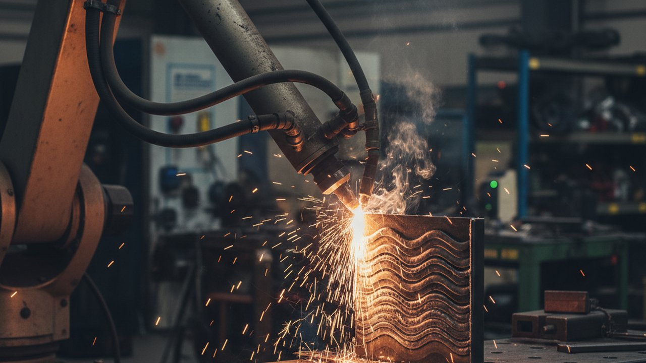
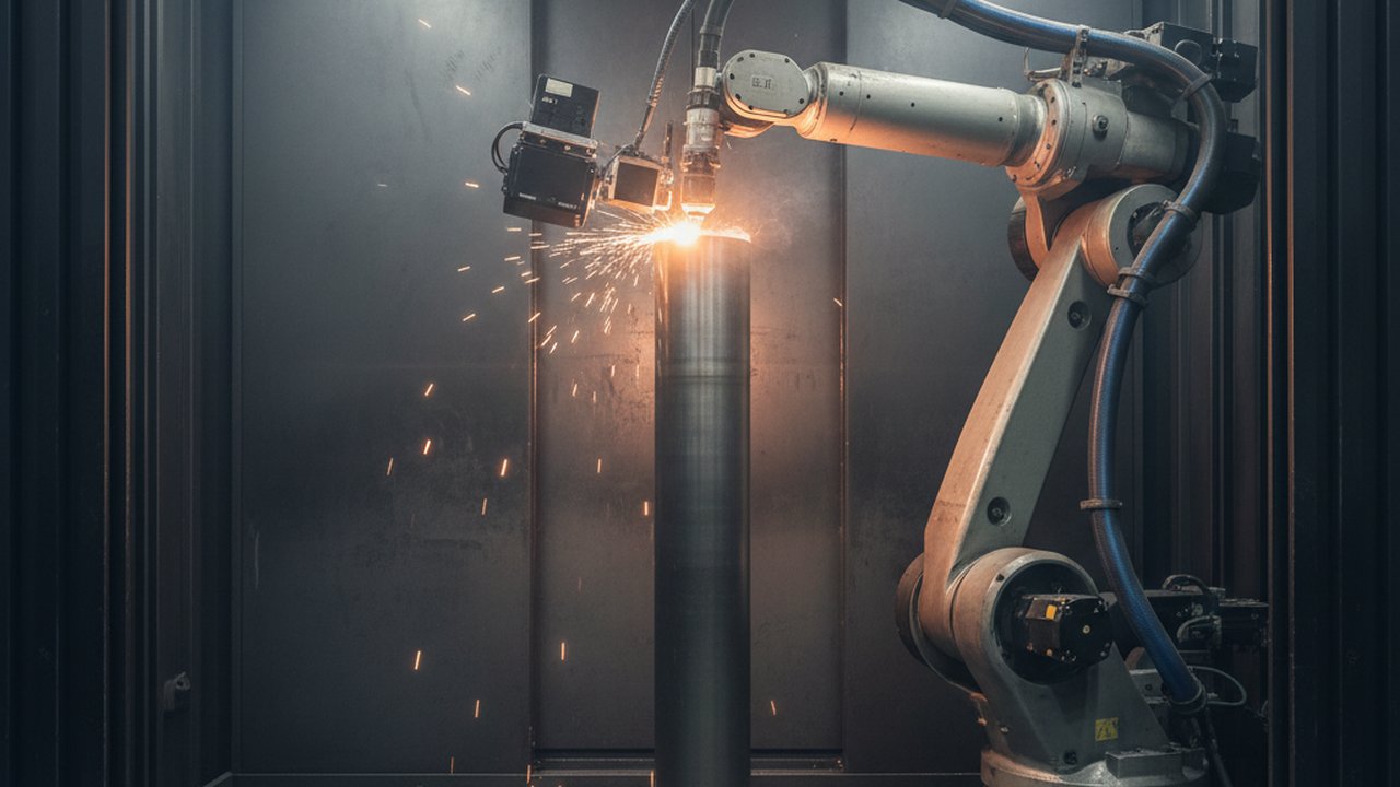
Carbon steel WAAM walls slump and widen the taller they get, and the reason is simple heat balance: every new layer lands on substrate that is warmer than the layer before it. The thermal video below makes that accumulation visible in real time — watch closely and the high-temperature region behind the arc visibly grows from the early passes to the later ones, even though the process parameters never changed.
That growth is not cosmetic. Rising interlayer temperature slows cooling, keeps the melt pool fluid longer, lets it spread further under its own weight, and — for carbon steel specifically — changes the microstructure of every layer it reheats on the way. This guide covers the physics behind the slump, what it looks like frame by frame in thermal footage, why carbon steel responds the way it does, and how to build an interlayer temperature control strategy that keeps a tall wall on-spec.
Key Takeaways
- WAAM walls accumulate heat because thermal mass grows with every layer while the surface area available to shed that heat does not grow proportionally.
- Rising interlayer temperature widens the melt pool and can slump a tall wall out of its intended cross-section well before the top layer is reached.
- Carbon steel is particularly sensitive because its mechanical properties depend on cooling rate through the austenite-to-ferrite transformation range — a range that heat accumulation directly slows.
- Repeated reheating of already-deposited layers can temper, coarsen, or soften the heat-affected zones stacked through the build, not just change the top surface.
- A thermal camera reading peak interlayer temperature per layer can flag a rising trend several layers before geometric slump becomes measurable.
- Interlayer dwell time is an effective but time-costly control lever, and is usually tuned after travel speed and heat input rather than instead of them.
- Catching accumulation early — while machining allowance still covers the drift — is the difference between a finish-machined part and a scrapped one.
Why Heat Has Nowhere to Go in a Tall WAAM Wall
The Heat Balance Behind Each Bead
Every weld bead deposits a fixed amount of thermal energy into the part, and that energy has to go somewhere: into raising local temperature, into conduction through the substrate, or into radiation and convection from exposed surfaces. On the first few layers, the substrate below is large, cool, and close, so it absorbs heat efficiently and the bead cools quickly. As the wall grows taller, the conduction path to a cool heat sink lengthens, and the wall’s own accumulated thermal mass keeps a growing volume of material above ambient temperature.
Why Taller Walls Run Hotter Than the First Layers
The practical result is that interlayer temperature — the temperature of the previously deposited layer immediately before the next bead lands on it — tends to climb through a build even when travel speed, wire feed speed, and dwell time are held constant. This is the same physical effect that governs interpass temperature in multi-pass fusion welding, applied continuously across dozens or hundreds of layers instead of a handful of passes on a single joint.
A WAAM wall is, thermally, a long multi-pass weld standing on end. Every control principle that applies to interpass temperature in structural welding applies here — just repeated far more times, and with much less time between passes for heat to leave.
What Slump and Width Growth Look Like in the Thermal Video

Reading the Thermal Signature Pass by Pass
In the footage, the thermal camera shows the full heat distribution across the deposition zone, not a single point reading. What matters for spotting accumulation is not the peak temperature at the arc — that stays roughly similar pass to pass — but how far the elevated-temperature region extends behind and around the arc, and how close the previous layer is to its target interlayer window when the next pass begins. A stable process shows a consistent thermal footprint from layer to layer; an accumulating one shows that footprint growing.
From Widening Melt Pool to Geometric Drift
A wider thermal footprint means the melt pool itself stays fluid over a larger area for longer, which is the direct mechanical link to slump: a pool that spreads further before solidifying deposits a wider, flatter bead than the same wire feed and travel speed produced on a cooler substrate. Stack enough of those slightly-too-wide beads and the wall’s cross-section drifts outward from its design profile — sometimes gradually enough that no single layer looks wrong, but the finished wall is measurably out of tolerance.
Why Carbon Steel Specifically Is Sensitive to This
Repeated Reheating and the Layer Below
Carbon and low-alloy steel properties in a weld or WAAM build are set largely by the cooling rate the material experiences through its transformation range on the way down from peak temperature — the same physics behind t8/5 cooling-time control in conventional multi-pass welding. In a WAAM wall, every layer deposited above a given point re-exposes that point to another thermal cycle, without fully re-melting it. Depending on the peak temperature reached during that reheating, the layer below can be tempered, its grain structure can coarsen, or its hardness can shift — an effect that stacks through the build, so the material several layers below the current deposition zone has a different thermal history than the top layer does.
Cooling Rate Through the Transformation Range
As interlayer temperature rises through a build, the temperature difference driving conductive cooling shrinks, and each new layer’s own cooling rate through the transformation range slows down. A slower cooling rate generally produces a softer, coarser-grained structure in carbon steel than a faster one — the opposite direction from the concern in high-hardenability steels, where cooling too fast risks hardening and cracking. For carbon steel WAAM specifically, unmanaged heat accumulation trends toward excessive softening and grain coarsening rather than hardening, on top of the geometric slump risk covered above.
For alloy-specific interlayer temperature limits and target cooling windows — which vary by material and are not reproduced here — see WAAM interlayer temperature control: limits, methods, defects.
Standards and Where Interlayer Temperature Limits Live
ISO/ASTM 52900 supplies the shared vocabulary for WAAM as a directed energy deposition process — the terminology base both AWS and ASTM documents now reference. AWS D20.1/D20.1M, the Specification for Fabrication of Metal Components Using Additive Manufacturing, covers wire-fed arc systems and requires that thermal process parameters — including interlayer conditions — be established under the qualified procedure, without a single universal interlayer number: the procedure and the material’s own transformation behavior set that window for each job.
Because a WAAM wall is fundamentally a stack of fusion welds, the interpass-temperature principles in AWS’s structural welding code family — developed for multi-pass joints — remain the closest conventional analogue. ASTM F3187, the Standard Guide for Directed Energy Deposition of Metals, frames the expectation that DED processes document process and system monitoring, which for carbon steel WAAM means the per-layer thermal record described below.
Step-by-Step Implementation: Controlling Interlayer Temperature on a Carbon Steel Wall
- Set a target interlayer temperature window for the specific carbon steel grade and section thickness in the qualified procedure, before deposition starts — not as a reaction once slump is observed.
- Instrument the build with a thermal camera — a compact LWIR sensor such as HeatCam IR-S with a clear line of sight to the deposition zone, positioned to avoid direct arc radiation in the field of view.
- Log peak interlayer temperature per layer, tagged with layer number and timestamp, so the trend across the build is reviewable, not just the current reading.
- Build a short calibration wall (10 to 15 layers) at the planned process parameters and plot interlayer temperature against layer number to see whether it stabilizes or keeps climbing.
- If the trend keeps climbing, add interlayer dwell — a programmed pause before the next layer starts — sized to bring peak temperature back into the target window before proceeding.
- Re-verify bead width at intervals through the full-height build, not only at the end, to confirm the dwell strategy is actually holding geometry steady as height increases.
- Document the qualified dwell schedule and thermal log alongside the WFS/travel-speed procedure as part of the build record.
Common Failure Modes and Fixes
| Symptom | Likely cause | Fix |
|---|---|---|
| Thermal footprint visibly widens layer over layer with no plateau | No interlayer dwell, or dwell too short for the wall’s growing thermal mass | Add or extend interlayer dwell, recalculated periodically as the wall gets taller |
| Interlayer temperature plateaus but bead width still drifts | Dwell holding temperature but travel speed no longer matched to the resulting pool behavior | Re-run the bead-width calibration at the now-stable interlayer temperature, not the cold-start value |
| Wall leans or bulges asymmetrically | Uneven heat sink — one side of the wall has better conductive path than the other | Check fixturing and substrate contact; consider alternating deposition direction to average heat distribution |
| Hardness lower than expected in mid-build sections after finishing | Repeated reheating from later layers softened earlier ones | Reduce interlayer temperature target for that grade; verify with hardness spot checks at planned inspection points |
| Camera reads a hot spot that does not match the visible arc position | Reflected radiation off oxide scale or fixturing, not true substrate temperature | Re-verify emissivity setting for the actual surface condition and re-check camera field of view for reflective surfaces |
Verification: Confirming the Wall Stayed Within Its Thermal Window
Verification for a carbon steel WAAM build closes two separate loops. The first is the thermal record: review the per-layer peak interlayer temperature log against the target window from procedure qualification, flagging any layer where the peak exceeded it rather than only checking the average. The second is the geometric and metallurgical record: dimensional measurement of the finished wall against the design envelope, plus hardness or microstructure spot checks where the specification calls for them — the thermal log shows where accumulation happened, but only a physical check confirms what it did to the part.
A thermal log showing a clean, stable interlayer temperature trend is strong supporting evidence of a well-controlled build, but it does not replace the physical inspection a structural or pressure-retaining part requires; it makes that inspection targeted, by pointing directly at the layers where a deviation actually occurred instead of forcing a blind full-height check.
FAQ
Why do carbon steel WAAM walls slump as they get taller?
Each new layer deposits onto substrate that is already warmer than the layer before it, because a taller wall has more accumulated thermal mass and less relative surface area to lose heat from. Rising interlayer temperature keeps the melt pool fluid longer, letting it spread further under gravity before it solidifies, which widens the bead and can slump the wall out of its intended profile.
What does a widening melt pool in a WAAM thermal video actually indicate?
A visibly widening high-temperature region pass over pass in thermal footage indicates that interlayer temperature is climbing faster than it is dissipating between layers. It is a direct visual signature of heat accumulation outrunning the build’s cooling capacity, and it typically precedes measurable geometric drift in the finished wall.
Does heat accumulation in WAAM affect carbon steel differently than other alloys?
Carbon and low-alloy steels are sensitive to cooling rate through their austenite-to-ferrite transformation range, so a slowing cooling rate as interlayer temperature rises changes the resulting microstructure and hardness in the repeatedly reheated zones, not just the final layer. Alloys with different transformation behavior respond to the same heat accumulation with different microstructural consequences.
What happens metallurgically when a carbon steel WAAM layer is reheated by the layers deposited after it?
Each subsequent layer re-exposes the material below it to a thermal cycle in the tempering or intercritical range without fully re-melting it, which can temper martensite formed on the previous cool-down, coarsen grain structure locally, and gradually reduce hardness in the heat-affected zones stacked through the build.
How does interlayer dwell time control heat accumulation in a WAAM wall?
Pausing between layers gives the previously deposited bead time to conduct and radiate heat away before the next layer is added on top of it, resetting interlayer temperature closer to the target window. Longer dwell reduces accumulation but adds build time, so dwell is usually the last lever adjusted after travel speed and heat input are already optimized.
Can a thermal camera predict wall slump before it happens?
Yes — a rising trend in peak interlayer temperature across successive layers, visible in per-layer thermal logging, predicts geometric drift before it is measurable on the finished part, because the temperature rise precedes the pool-spreading behavior that causes slump by several layers.
Is a slumped WAAM wall a scrap part or can it be reworked?
It depends on how far the geometry has drifted from the design envelope and whether machining allowance remains. A wall caught early, with only local width growth near the finish size, can often be finish-machined back to tolerance; a wall that has visibly leaned or lost its planned cross-section through multiple layers usually cannot be recovered and should be scrapped before further material is added on top of the defect.
The video analyzed here is Carbon Steel WAAM Thermal Imaging; the visual, non-thermal side of the same build process is covered in 3D Printing With Metal — WAAM, Layer Upon Layer and in how wire feed speed controls WAAM bead width. For alloy-specific interlayer limits and a broader defect list, see WAAM interlayer temperature control; for the full monitoring architecture, see the WAAM additive manufacturing monitoring hub and thermography NDT testing. Two calculators help here: the t8/5 cooling time calculator estimates cooling rate through the transformation range from heat input and interlayer temperature, and the heat input calculator ties arc energy per unit length back to how much heat each pass contributes to the accumulation above.
Further background: TWI’s overview of arc-based additive manufacturing, ORNL’s published work on thermal process monitoring for wire-arc additive manufacturing using IR cameras, NIST’s paper on metal AM standardization for qualification and certification, ASME’s additive manufacturing content collection, a peer-reviewed study on interlayer temperature effects in high-strength metal-cored wire steel, and a ScienceDirect review of WAAM hardware, monitoring, and process control.
Log Interlayer Temperature on Every Layer, Automatically
HeatCam IR-S measures the full thermal field of a carbon steel WAAM build in real time, so a rising interlayer temperature trend is visible — and actionable — long before it shows up as slump in the finished wall. Talk to us about fitting it to your build cell.
Talk to us about HeatCam IR-STherness solution: Welding parameter monitoring — Current, voltage, wire feed and gas recorded per weld, as WPS/PQR and heat-input evidence.
Frequently Asked Questions
Why do carbon steel WAAM walls slump as they get taller?
Each new layer deposits onto substrate that is already warmer than the layer before it, because a taller wall has more accumulated thermal mass and less relative surface area to lose heat from. Rising interlayer temperature keeps the melt pool fluid longer, letting it spread further under gravity before it solidifies, which widens the bead and can slump the wall out of its intended profile.
What does a widening melt pool in a WAAM thermal video actually indicate?
A visibly widening high-temperature region pass over pass in thermal footage indicates that interlayer temperature is climbing faster than it is dissipating between layers. It is a direct visual signature of heat accumulation outrunning the build's cooling capacity, and it typically precedes measurable geometric drift in the finished wall.
Does heat accumulation in WAAM affect carbon steel differently than other alloys?
Carbon and low-alloy steels are sensitive to cooling rate through their austenite-to-ferrite transformation range, so a slowing cooling rate as interlayer temperature rises changes the resulting microstructure and hardness in the repeatedly reheated zones, not just the final layer. Alloys with different transformation behavior respond to the same heat accumulation with different microstructural consequences.
What happens metallurgically when a carbon steel WAAM layer is reheated by the layers deposited after it?
Each subsequent layer re-exposes the material below it to a thermal cycle in the tempering or intercritical range without fully re-melting it, which can temper martensite formed on the previous cool-down, coarsen grain structure locally, and gradually reduce hardness in the heat-affected zones stacked through the build.
How does interlayer dwell time control heat accumulation in a WAAM wall?
Pausing between layers gives the previously deposited bead time to conduct and radiate heat away before the next layer is added on top of it, resetting interlayer temperature closer to the target window. Longer dwell reduces accumulation but adds build time, so dwell is usually the last lever adjusted after travel speed and heat input are already optimized.
Can a thermal camera predict wall slump before it happens?
Yes — a rising trend in peak interlayer temperature across successive layers, visible in per-layer thermal logging, predicts geometric drift before it is measurable on the finished part, because the temperature rise precedes the pool-spreading behavior that causes slump by several layers.
Is a slumped WAAM wall a scrap part or can it be reworked?
It depends on how far the geometry has drifted from the design envelope and whether machining allowance remains. A wall caught early, with only local width growth near the finish size, can often be finish-machined back to tolerance; a wall that has visibly leaned or lost its planned cross-section through multiple layers usually cannot be recovered and should be scrapped before further material is added on top of the defect.
Related Video