Overlay cladding puts a corrosion-resistant alloy over a cheaper base metal, and two process variables decide whether that layer actually protects anything: dilution, how much base metal ends up mixed into the deposit, and bead overlap, how completely each pass covers the one before it. Get either wrong and the finished surface can look like a sound overlay while carrying less of the intended alloy than the specification assumes, in either the whole layer or just the valleys between passes. Real-time monitoring exists to catch that drift while the pass is still running, not after the component is in service. This article covers what dilution and overlap actually do to corrosion performance, what thermal and visual monitoring each detect during deposition, and how to turn that into an alert rule you can trust.
Key takeaways
- Dilution pulls the deposit’s chemistry toward the base metal; bead overlap decides whether every point on the surface gets the intended overlay thickness at all.
- The two failure modes are independent: a pass can sit inside its qualified dilution range and still leave an under-covered valley if the next pass does not overlap it enough.
- Thermal monitoring reads surface heat: peak temperature just behind the pool, the surface thermal-footprint width, and interpass temperature — signals that correlate with penetration depth rather than measure the fusion line or the heat-affected zone directly.
- Visual and weld-pool imaging read geometry: actual bead width and stepover coverage, which thermal data alone cannot confirm.
- An alert threshold copied from a table or a different job is not a threshold; baseline it on your own qualified pass first.
- Verify an alert rule by deliberately running a marginal pass and confirming the alert fires during that pass, not only in the after-weld report.
How dilution decides overlay corrosion performance
Every overlay pass mixes two sources of metal: the filler being deposited and the base metal the arc melts as it advances. Dilution is the share that comes from the base metal, and it is controlled by the same variables that govern penetration on any weld: heat input, travel speed, and the process itself. A single-pass, high-energy process drives molten base metal deep into the weld pool and dilutes heavily. Strip cladding dilutes far less because its wide, shallow arc spreads energy over a large area instead of digging into the substrate; in any multi-layer overlay, the upper layers dilute less again for a separate reason, because they mostly fuse into the previously deposited layer rather than into the original base metal.
The reason dilution matters specifically here, and barely matters on an ordinary structural weld, is that overlay welding exists to change the surface chemistry on purpose. Filler and base metal are usually similar alloys in a structural joint, so a shift in mix changes little. On a corrosion-resistant overlay the filler is deliberately a different, more expensive alloy, and dilution is what determines how much of the cheaper base metal ends up inside the layer meant to protect it. Push dilution too high on a given pass and the deposit’s corrosion-resisting elements are diluted below what the qualified procedure assumed, even though nothing about the bead looks wrong from outside.
Acceptable dilution is not a number you can read off a generic table. It is set for your specific base-metal and filler pairing during procedure qualification, confirmed by chemical analysis of the deposit under ASME Section IX or, on an ISO/EN route, ISO 15614-7, the overlay-welding part of the ISO 15614 series, and recorded in that job’s WPQR. Ask for the qualification chemistry rather than assuming a percentage carried over from a different alloy or a different job.
Bead overlap: the coverage variable dilution control does not fix
Bead overlap is how much of one pass’s width the next adjacent pass covers as the overlay is built up track by track. It is a process parameter you set on the deposition program, not a discontinuity, and it can go wrong in a properly diluted procedure.
If overlap is too small, a valley remains between adjacent beads where the deposit is thinner and sits closer to the original fusion line than the flat of either bead does. After any post-weld machining allowance is removed, that valley can end up with less corrosion-resistant thickness above it than the rest of the surface, even where every pass individually tested inside its qualified dilution range. The failure is invisible from a chemistry check on a single bead because it is a geometry problem, not a composition problem.
On dilution, overlap pulls the opposite way it does on coverage: within limits, more overlap tends to lower averaged dilution, because more of each new pass fuses into the previously deposited overlay metal rather than into virgin base metal. Push it too far past that point and a different mechanism takes over. Each new pass reheats more of the one before it, interpass temperature climbs, and at unchanged welding parameters the arc can drive deeper into the toe of the previous bead. That heat buildup also wastes deposition efficiency and puts unnecessary heat into the part for no coverage gain. Neither extreme shows up as an obvious visual defect at the time; too little overlap shows up later as a coverage gap, too much shows up as excess heat input or a thermal excursion at the toe of the previous bead.
This is a genuinely different thing from the ISO 6520-1 reference 506 defect, which also carries the name overlap: that is weld metal folded over a toe or root without fusing to the parent material underneath, covered on the overlap defect reference card. The two share a name and nothing else — a badly aimed, cold pool can produce the 506 fold defect on a single bead regardless of how the deposition program spaces its passes.
What thermal and visual monitoring each detect during deposition

Thermal and visual monitoring see different physics, which is why an overlay monitoring setup needs both rather than either one alone.
| Signal | What it reads | What it catches |
|---|---|---|
| Peak surface temperature at and just behind the pool | How much heat the surface is carrying as the arc passes | Correlates with penetration depth and, with it, dilution risk |
| Surface thermal-footprint width | How far the surface heat spreads behind the pool | Whether heat input is concentrated or spreading in a way that raises dilution risk |
| Interpass temperature | Residual heat left by the previous pass before the next one starts | Whether a hot section will reach the same melting depth at a lower arc energy than a cold start |
| Weld-pool / bead-width imaging | Actual pool and bead geometry as the pass runs | Whether the current pass is covering enough of the previous one to close the overlap gap |
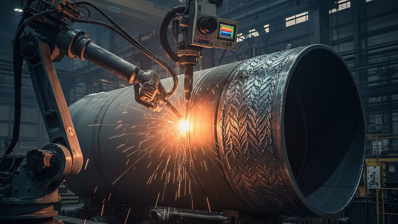
Thermal imaging cannot confirm overlap coverage directly, because a well-covered valley and an under-covered one can carry a similar surface temperature if both passes ran the same parameters. Visual and weld-pool imaging cannot confirm dilution directly, because chemistry is not visible on a camera. A monitoring stack such as HeatCore AI, reading a thermal camera like HeatCam IR-C alongside a weld-pool camera such as PoolDrop, scores both signals together on the same pass rather than treating dilution and coverage as one problem.
Setting an alert rule: a practical walkthrough
Copying a threshold from a different job, or from a generic table, gives you an alert that fires at the wrong point for your alloy, thickness, and joint. Build the rule from your own qualified pass instead.
- Start from the qualified procedure, not a table. Pull the dilution range and any post-machining minimum overlay thickness your WPS and WPQR already establish for this alloy pairing.
- Run a baseline pass known to sit inside that qualified range, and record its thermal signature: peak surface temperature behind the pool, surface thermal-footprint width, and interpass temperature if it is a multi-pass sequence.
- Record the baseline overlap from weld-pool or bead-width imaging on that same pass, so you know what in-spec coverage actually looks like on your equipment, not a generic percentage.
- Set the alert as a deviation band from that baseline, on both signals, rather than an absolute number. A thermal excursion beyond the baseline band flags a dilution risk; a coverage reading below the baseline flags an overlap gap.
- Route the alert to something that can act during the pass. On a robotic or mechanised cell that means an interlock the controller can pause or correct on; on a manual pass it means an operator cue fast enough to adjust travel speed, current, or torch aim before the next pass compounds the drift.
- Re-baseline whenever the alloy pairing, thickness, or joint geometry changes. A threshold built for one overlay chemistry or one deposition pattern does not transfer to another without re-running steps two and three.
Verification: proving the alert fires during deposition, not after it
An alert rule that only agrees with a post-weld chemical analysis or a dimensional check after the fact is not giving you a real-time signal, it is giving you a slower way to confirm what already happened. The way to check this is the same paired comparison used to set the rule in the first place, run deliberately rather than left to chance.
Run a pass with a known, deliberate deviation, either heat input pushed toward the edge of the qualified dilution range or overlap deliberately reduced, under controlled conditions rather than in production. Compare the timestamp of the monitoring alert against the point in the video or thermal record where the deviation is actually visible. An alert that only agrees with a post-weld cross-section or chemical analysis is not catching the deviation while it can still be corrected. Repeat this check whenever the procedure, alloy, or deposition pattern changes, because both the thermal baseline and the overlap baseline move with all three.
Standards that govern qualification, not this article
ASME Section IX governs qualification of the welding procedure and the welders producing the overlay, including the chemical analysis and testing that establishes an acceptable dilution range for a given alloy pairing; work built to an ISO or EN route uses ISO 15614-7, the overlay-welding part of the ISO 15614 series, instead. Once the overlay is finished, general quality-level acceptance criteria such as ISO 5817 apply to the imperfections classified under ISO 6520-1, including the fold-type overlap defect covered above, without this article restating either standard’s numeric limits: those live in the standard and the job’s own WPQR, not in a blog post.
From monitoring to catching drift while it can still be corrected
Reading a thermal or pool-imaging record after the fact tells you what happened. Catching a dilution excursion or an overlap gap while the pass is still running is what an in-process monitoring stack is for. For the fuller picture of thermal-imaging-based overlay quality monitoring, including defect types beyond dilution and overlap, see Weld Overlay Cladding Monitoring with Thermal Imaging. For the full clip this article draws its walkthrough from, see Cladding Process Monitoring with HeatCore. And to check a specific pass’s expected dilution against your process parameters before you ever strike an arc, use the weld dilution calculator.
FAQ
What is dilution in weld overlay cladding, and why does it matter for corrosion resistance? Dilution is the share of the deposited overlay that comes from melted base metal rather than filler. The overlay’s corrosion resistance depends on the filler’s chemistry, typically its nickel or chromium content, and dilution pulls that chemistry toward the far less resistant base metal. Push dilution too high on a given pass and that section of the layer can test out closer to a diluted mix than to the intended corrosion-resistant grade, even though the bead looks sound on the surface.
How much dilution is acceptable on a corrosion-resistant overlay? There is no single number that applies across alloys and processes. Acceptable dilution is set by the qualified welding procedure for that specific base metal and filler pairing, and confirmed by chemical analysis of the deposit during procedure qualification. Ask for the WPQR’s chemistry results for your alloy pair rather than assuming a percentage from a different job or a different filler.
What is bead overlap in overlay cladding, and how is it different from the ISO 6520-1 overlap defect? Bead overlap here is a process parameter: how much of one pass width the next adjacent pass covers. It is a stepover setting, not a discontinuity. The ISO 6520-1 reference 506 defect, also called overlap, is a different thing entirely: weld metal folded over a toe or root without fusing to the parent material beneath it. The names collide by coincidence; the mechanisms and the fixes do not.
Why does bead overlap affect corrosion performance if dilution is already controlled? Coverage, not chemistry. If one pass does not cover enough of the previous one, a valley remains between the two beads where the overlay is thinner and sits closer to the fusion line. After any post-weld machining allowance is removed, that valley can carry less corrosion-resistant thickness than the flat of the bead does, even where the deposit chemistry everywhere else is well inside the qualified range. Too much overlap has its own cost: it reheats more of the previous pass, which raises interpass temperature and can drive the arc deeper into the toe of that pass at the same welding parameters, on top of wasting deposition efficiency and adding heat the part does not need.
What does thermal monitoring actually detect during overlay deposition? Peak surface temperature at and just behind the pool, and the width of the surface thermal footprint trailing it, both of which correlate with how deep the arc is melting into the base metal, the physical driver of dilution, without measuring the sub-surface fusion line or the heat-affected zone directly. It also tracks interpass temperature between overlapping passes, because a section that stayed hot from the previous pass reaches the same depth of melting at a lower arc energy than a cold start needs.
Can visual or weld-pool imaging catch a bead overlap problem that thermal monitoring misses? Yes, because the two read different things. Thermal imaging reads heat, not geometry, so a torch path that drifted and left a gap between passes does not necessarily show up as a temperature anomaly. Weld-pool imaging shows the actual bead width and stepover while the pass is running, which is the direct check on overlap coverage rather than an inference from heat.
How do you set an alert rule for dilution or overlap during overlay deposition? Baseline it on a qualified pass first. Run a test pass known to sit inside your procedure’s dilution range, record its thermal signature (peak surface temperature, surface thermal-footprint width, interpass temperature) and its measured bead overlap from pool imaging, then set the alert as a deviation band from that baseline rather than an absolute figure carried over from a different job or alloy. Confirm the alert actually fires by deliberately running a marginal pass before relying on it in production.
What should happen when a dilution or overlap alert fires mid-deposition? The pass in progress should be interrupted or corrected, not just logged for the after-weld report. On a mechanised or robotic cell that means an interlock the controller can act on immediately, pausing travel or adjusting current. On a manual pass it means an operator cue fast enough to correct heat input, travel speed, or torch aim before the next pass compounds the same deviation.
Catch dilution and overlap drift while a pass is still running
HeatCore AI reads thermal and weld-pool signals together during overlay deposition, so a dilution or coverage problem is flagged on the pass in progress instead of found on final inspection.
Talk to an engineerTherness solution: Welding parameter monitoring — Current, voltage, wire feed and gas recorded per weld, as WPS/PQR and heat-input evidence.
Frequently Asked Questions
What is dilution in weld overlay cladding, and why does it matter for corrosion resistance?
Dilution is the share of the deposited overlay that comes from melted base metal rather than filler. The overlay's corrosion resistance depends on the filler's chemistry, typically its nickel or chromium content, and dilution pulls that chemistry toward the far less resistant base metal. Push dilution too high on a given pass and that section of the layer can test out closer to a diluted mix than to the intended corrosion-resistant grade, even though the bead looks sound on the surface.
How much dilution is acceptable on a corrosion-resistant overlay?
There is no single number that applies across alloys and processes. Acceptable dilution is set by the qualified welding procedure for that specific base metal and filler pairing, and confirmed by chemical analysis of the deposit during procedure qualification. Ask for the WPQR's chemistry results for your alloy pair rather than assuming a percentage from a different job or a different filler.
What is bead overlap in overlay cladding, and how is it different from the ISO 6520-1 overlap defect?
Bead overlap here is a process parameter: how much of one pass width the next adjacent pass covers. It is a stepover setting, not a discontinuity. The ISO 6520-1 reference 506 defect, also called overlap, is a different thing entirely: weld metal folded over a toe or root without fusing to the parent material beneath it. The names collide by coincidence; the mechanisms and the fixes do not.
Why does bead overlap affect corrosion performance if dilution is already controlled?
Coverage, not chemistry. If one pass does not cover enough of the previous one, a valley remains between the two beads where the overlay is thinner and sits closer to the fusion line. After any post-weld machining allowance is removed, that valley can carry less corrosion-resistant thickness than the flat of the bead does, even where the deposit chemistry everywhere else is well inside the qualified range. Too much overlap has its own cost: it reheats more of the previous pass, which raises interpass temperature and can drive the arc deeper into the toe of that pass at the same welding parameters, on top of wasting deposition efficiency and adding heat the part does not need.
What does thermal monitoring actually detect during overlay deposition?
Peak surface temperature at and just behind the pool, and the width of the surface thermal footprint trailing it, both of which correlate with how deep the arc is melting into the base metal, the physical driver of dilution, without measuring the sub-surface fusion line or the heat-affected zone directly. It also tracks interpass temperature between overlapping passes, because a section that stayed hot from the previous pass reaches the same depth of melting at a lower arc energy than a cold start needs.
Can visual or weld-pool imaging catch a bead overlap problem that thermal monitoring misses?
Yes, because the two read different things. Thermal imaging reads heat, not geometry, so a torch path that drifted and left a gap between passes does not necessarily show up as a temperature anomaly. Weld-pool imaging shows the actual bead width and stepover while the pass is running, which is the direct check on overlap coverage rather than an inference from heat.
How do you set an alert rule for dilution or overlap during overlay deposition?
Baseline it on a qualified pass first. Run a test pass known to sit inside your procedure's dilution range, record its thermal signature (peak surface temperature, surface thermal-footprint width, interpass temperature) and its measured bead overlap from pool imaging, then set the alert as a deviation band from that baseline rather than an absolute figure carried over from a different job or alloy. Confirm the alert actually fires by deliberately running a marginal pass before relying on it in production.
What should happen when a dilution or overlap alert fires mid-deposition?
The pass in progress should be interrupted or corrected, not just logged for the after-weld report. On a mechanised or robotic cell that means an interlock the controller can act on immediately, pausing travel or adjusting current. On a manual pass it means an operator cue fast enough to correct heat input, travel speed, or torch aim before the next pass compounds the same deviation.