Most shops do not buy their welding machines in one batch. A line that grew over fifteen years runs inverter power sources from different manufacturers next to older units with no data port at all, some in robotic cells and some on manual stations. When the quality plan asks for a record of what each weld actually received, the first question is not which software to use. It is where the voltage, current and wire feed speed will come from on each machine.
There are three routes: read the machine’s own data interface, measure the quantities with an external acquisition unit, or take them from the PLC or robot controller. Each works. Each also loses something different: sampling rate, synchronisation with the weld path, or comparability between machines. This article sets out what each route delivers, what it drops, and how to plan a retrofit machine by machine. For what a parameter record is for in the first place, see recording what the welding machine actually delivered.
Key takeaways
- A mixed fleet usually needs more than one acquisition route. That is fine as long as the record defines each channel the same way on every station.
- The machine data interface is the cheapest route where it exists. Read its documentation for set-versus-measured values, averaging and update rate before treating it as evidence.
- An external acquisition unit measures the quantities itself, so old and new machines produce channels with the same sampling basis.
- PLC and robot controller tags are the reference for position, program step and arc state. They carry electrical values only as fast and as accurately as the PLC receives them.
- Plan the retrofit from an inventory: one row per machine, one route per channel, one synchronisation reference per station.
Route 1: the machine data interface
Many current inverter power sources expose process values over a digital interface. Where that interface exists and is documented, it is the lowest-effort route: no extra hardware at the torch or cable, and the values arrive already digitised.
Four questions decide whether those values are usable as a record:
- Set or measured? Some interfaces report the programmed value, which is what the machine was told to deliver, not what it delivered. A record built from set values cannot show a deviation from them.
- Averaged or sampled? A value averaged over an interval smooths out exactly the short events that point to a fault: a contact-tip problem, a wire-feed stumble, a gas dropout.
- How fast? The update rate is fixed by the manufacturer. It may be adequate for a per-weld summary and too slow to resolve a transient.
- Same definitions across makes? Two manufacturers can report “current” with different filtering or averaging. Their numbers look the same in a table but are not comparable.
None of these questions can be answered generically. The answer sits in the interface documentation of each machine, and it has to be written into the record’s metadata so an auditor reading the data knows what it represents.
Route 2: an external acquisition unit
The second route measures the process quantities independently of the power source. It adds hardware per station, but it removes the dependency on what each machine chooses to report. An old power source with no data port and a new one with a full interface produce the same channels, at the same sampling rate, with the same definitions.
This is the route that makes cross-fleet comparison straightforward. If station 4 and station 11 run the same WPS on different machines, the records show whether they delivered the same process, because both were measured the same way.
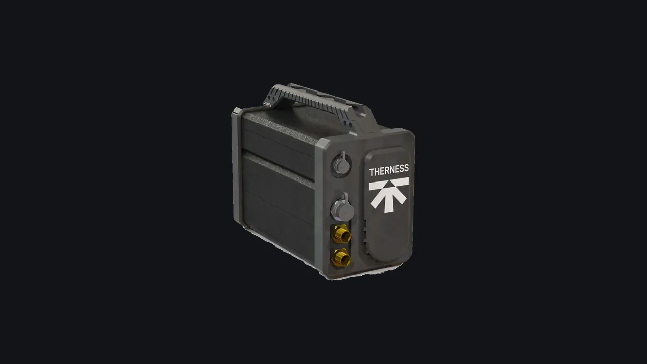
WeldTrace is built for this route. It records voltage, current and wire feed speed simultaneously at 25 kHz and shielding gas flow at 10 Hz. It connects over a single Ethernet cable that carries power and data, and is operated through a browser-based HMI with no client software. Each channel has its own calibration and adjustable acquisition rate. That sampling rate is high enough to resolve the short electrical events that an averaged interface value hides.
A channel is only comparable across machines if it was defined the same way on each: same quantity, same unit, same sampling basis, same start and stop reference. The acquisition route can vary per machine. The channel definition cannot.
Route 3: PLC and robot controller tags
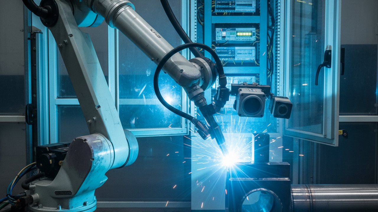
On automated stations, the PLC or robot controller already sits in the middle of the process. It knows which program step is running, where the torch is on the joint and when the arc is enabled. That context is what turns an electrical trace into a record of a specific joint and pass, as described in where each signal comes from in a robotic cell.
As a source for the electrical values themselves, the PLC is limited by what it receives. If the power source passes set values to the PLC, the tag carries set values. If the PLC reads the value once per scan cycle, the tag carries one value per scan. The PLC is the right place for context and synchronisation; the electrical channels may still need route 1 or route 2 behind it. How the tags, triggers and timestamps are wired in practice is covered in camera and PLC integration: wiring, sync and the data pipeline.
At Therness, the Weld Parameters module can take its data either from WeldTrace or from the separate PLC Integration module, which provides OPC-UA, Modbus TCP and Profinet connectivity. The choice follows the station, not a single fleet-wide rule.
What each route delivers and drops
| Machine interface | External acquisition unit | PLC / controller tags | |
|---|---|---|---|
| Extra hardware | None where the interface exists | One unit per station | None beyond existing PLC |
| Measured or set value | Depends on the machine | Measured | Whatever the PLC receives |
| Sampling basis | Fixed by the manufacturer | Set per channel, identical across machines | PLC scan rate |
| Short transients | Often averaged out | Resolved at a high sampling rate | Usually not resolved |
| Comparability across makes | Needs a per-machine definition check | Same definition on every machine | Inherits its source |
| Joint position and arc state | Not usually | Arc state derived from current; position from another source | Yes: the reference source |
The table is a starting point, not a verdict. A modern cell with a well-documented interface and a PLC may need nothing else. A manual station on a twenty-year-old power source has only one practical route.
Synchronisation: one reference per station
Whatever the route, every station needs one event that ties the electrical data to a specific weld. On automated stations the controller’s arc-on and arc-off signals, or its program step, provide it. On manual stations there is no controller; arc-on and arc-off can be derived from the measured current crossing a threshold, and the joint reference comes from the job card, a barcode scan or the operator’s selection at the station.
Without that reference, the fleet produces traces with timestamps and nothing to say which joint they belong to. That is a data problem that no amount of sampling rate fixes.
Planning the retrofit machine by machine
A practical retrofit starts with an inventory, one row per station:
- Machine: power source type and age, process (MIG/MAG, TIG, other), manual or automated.
- Interface: present or not; if present, set or measured values, averaging and update rate from the documentation.
- Controller: PLC or robot controller present; which signals are available (arc state, program step, position).
- Route per channel: which source provides voltage, current, wire feed speed and gas flow on this station.
- Sync reference: which event marks the start and end of each weld.
- Record link: how each weld is tied to the WPS, the welder or program, and the part, following the same fields as a digital WPS and PQR record.
Two rules keep the result usable. First, choose the route per channel, not per fleet: a station can take arc state from the PLC and current from an external unit. Second, fix the channel definitions before the first machine is connected, and apply them to every route. Retrofitting definitions after data exists means the early records cannot be compared with the later ones.
A pilot on two or three representative stations, typically one modern cell, one older machine and one manual station, shows whether the definitions hold across all three routes before the rest of the fleet is connected.
Map your fleet before you pick the hardware
Therness can help sort your stations by acquisition route and define the channels once, so records from old and new machines stay comparable.
Discuss your fleetTherness solution: Welding parameter monitoring — Current, voltage, wire feed and gas recorded per weld, as WPS/PQR and heat-input evidence.
Frequently Asked Questions
Can one record format cover power sources of different makes and ages?
Yes, if the record is defined by channel rather than by machine: the same quantities, units, sampling basis and arc-on/arc-off reference for every station. The acquisition route can differ per machine; the definition of each channel in the record cannot, or two stations with the same numbers will not mean the same thing.
What is lost when arc data is read from the machine data interface?
It depends on the interface. Some report set values rather than measured ones, some report a value averaged over an interval, and the update rate is fixed by the manufacturer. Short transients such as a wire-feed stumble can disappear inside that averaging. The route is convenient where it exists, but its sampling basis has to be read from the documentation before the data is used as evidence.
When is an external acquisition unit the better route?
When a machine has no usable data port, when its interface reports set values rather than delivered values, or when several machines must produce records with the same sampling basis. An external unit measures the quantities itself, so an old power source and a new one produce comparable channels.
Are PLC tags enough to document what each weld received?
PLC tags are the reference for where the torch is, which program step is running and when the arc is on. As a source for voltage, current and wire feed speed they carry whatever the PLC receives, usually at the PLC scan rate. They are the right source for context and synchronisation; whether they are enough for the electrical record depends on what the PLC actually receives from the power source.
How are stations without a PLC or robot controller handled?
A manual station has no controller to supply arc state or joint position. The arc-on and arc-off events can be derived from the measured current itself, and the joint or part reference comes from the job card or a scan at the station. The electrical channels are recorded the same way as on automated stations.