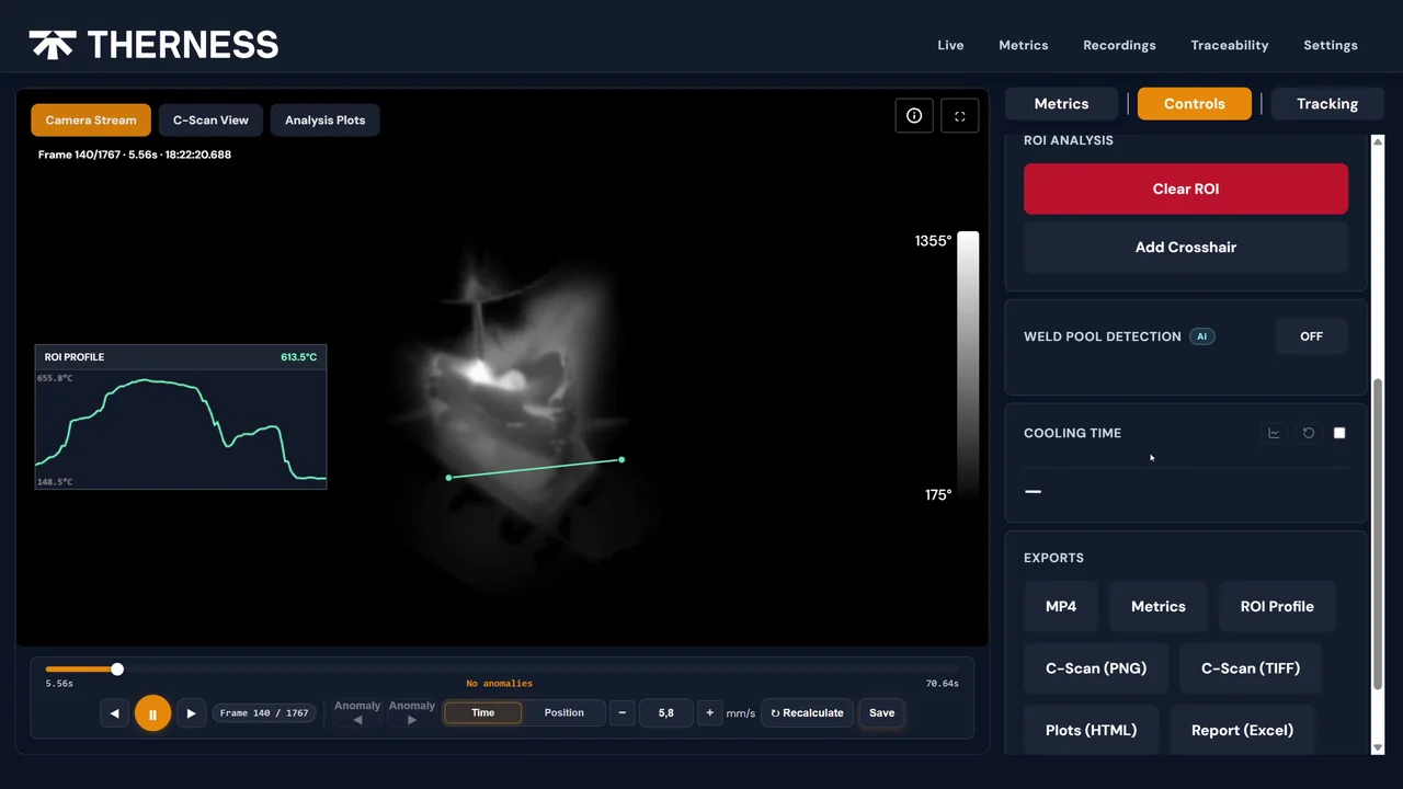
Welding camera PLC integration is what transforms a camera from a passive recording device into an active quality-control node in a robotic or automated welding cell. Without a wired connection to the PLC or robot controller, the camera captures arc light on a standalone clock — footage that is time-stamped but never cross-referenced to a specific joint, weld sequence, or part serial number. With integration, every frame carries structured metadata: part ID, programme step, arc-on event, WPS reference. That metadata is what ISO 3834 compliance, EN 15085 railway audit trails, and automotive PPAP packages actually require.
This guide covers the full signal architecture — from the 24 V digital I/O trigger wire to the MES data pipeline — with a wiring diagram, common failure modes, a step-by-step commissioning procedure, and validation metrics. Whether your cell runs a welding camera for industrial automation on a Profinet PLC, an EtherNet/IP PLC, or a robot-native I/O interface, the integration principles are the same.
Key Takeaways
- Welding camera PLC integration requires hardware triggering — not software polling — to guarantee sub-2 ms latency between the arc-enable signal and the first captured frame.
- Digital I/O (24 V DC, optocoupled) is the simplest and most reliable trigger path; Profinet and EtherNet/IP add richer metadata exchange at the cost of higher configuration effort.
- The camera, PLC, and robot controller must share a common time reference (PTP/NTP) before any frame-to-event correlation is meaningful.
- ISO 3834-2 requires six minimum fields per joint record: timestamp, part serial, joint ID, WPS reference, programme step, and camera file path.
- EMI from the welding arc is the single most common cause of spurious triggers and dropped frames — proper cable shielding and VLAN isolation reduce this to near zero.
- Camera footage does not replace power-source data (current, voltage, heat input); both sources must be ingested into a shared per-joint record.
- Validate the integration with a quantitative timing procedure before production; re-validate after every PLC programme change that modifies weld sequence logic.
Table of Contents
- Why PLC and Robot Integration Defines Camera Usefulness
- Signal Architecture: Digital I/O, Ethernet/IP and Profinet
- Wiring the Arc-Enable Hardware Trigger
- Data Pipeline: From Camera to MES and ERP
- Common Integration Failure Modes and Fixes
- Step-by-Step Integration Commissioning
- Validation and Verification Procedure
- Standards and ISO 3834 Traceability Requirements
- Integration Decision Framework
- FAQ
Why PLC and Robot Integration Defines Camera Usefulness
A standalone welding camera records footage. An integrated welding camera records evidence. The distinction is traceable metadata. When a quality auditor requests the arc footage for weld joint W-0147 on part serial 2026-04-17-0023 using WPS EN-ISO-15614-1-MAG-S355, a standalone camera offers a file timestamp and nothing else. The auditor must manually cross-reference the timestamp against the WPS log, the robot programme, and the part traveller — work that takes hours and introduces human error.
An integrated camera writes all six fields — timestamp, part serial, joint ID, WPS reference, programme step, camera file path — into the record at arc ignition. The auditor retrieves a single structured record. This is the practical difference between a welding monitoring system that satisfies an ISO 3834 audit and one that does not.
For robotic welding cells, integration also enables real-time feedback loops. The camera detects an anomaly — arc wander, missing bead, excessive spatter — and the PLC logic can halt the cell, flag the joint, and request operator review before the robot moves to the next joint. This closes the quality loop that unintegrated cameras cannot close, regardless of image quality or frame rate. Watch a HeatCore AI live view on a weld to see that loop in action.
Signal Architecture: Digital I/O, Ethernet/IP and Profinet
Three integration paths exist. The right choice depends on how much metadata the application requires and what fieldbus the cell already runs.
Digital I/O: Simplest Arc-Sync Trigger
A 24 V DC digital output from the PLC or robot controller fires when the arc starts and resets when it stops. The camera input circuit is optocoupled — input impedance typically 1–4 kΩ — providing galvanic isolation from the arc circuit. This is the minimum viable integration: the camera knows arc-on and arc-off times, nothing else.
For cells where part identification is loaded by barcode scanner or manually by the operator before the weld sequence runs, digital I/O triggering combined with a simple naming convention — part scan creates a folder; each arc-enable pulse creates the next frame sequence in that folder — provides adequate traceability without fieldbus complexity.
EtherNet/IP: For Cells with EtherNet/IP Controllers
EtherNet/IP, standardised by ODVA, maps camera I/O and parameter registers to the PLC tag table. The camera appears as a standard EtherNet/IP adapter. The PLC produces part ID, joint number, and WPS code into a tag array; the camera consumes those tags and embeds them in every frame’s metadata without custom middleware. Data rates of 1,000 packets per second are achievable on a switched Gigabit Ethernet segment with sub-1 ms cycle time.
Profinet: For Profinet Controllers and Many European OEM Lines
Profinet, the IEC 61784-2-compliant industrial Ethernet standard widely used in European manufacturing, provides equivalent capability with deterministic real-time (RT) and isochronous real-time (IRT) options. A camera with a Profinet device interface appears in TIA Portal as a GSDML node — import the GSDML file, assign a device name, map camera registers to PLC data blocks. The integration procedure is identical to adding any other Profinet I/O device.
For cells that run neither EtherNet/IP nor Profinet, OPC-UA provides a vendor-neutral integration path supported by most modern PLCs, robot controllers, and industrial cameras. Programmable logic controllers conforming to IEC 61131-3 have supported external device integration via fieldbus adapters since the third edition; OPC-UA is the current convergence standard for cross-vendor data exchange.
For visible-band cameras — such as the Therness PoolDrop weld pool camera — and LWIR thermal cameras such as the HeatCam-IR-C, the fieldbus integration path is identical. The difference is in what the frame data contains: PoolDrop provides Class 1 laser-safe illuminated visible-spectrum weld pool images; HeatCam-IR-C provides calibrated LWIR thermal frames showing interpass temperature distribution. Both integrate over the same trigger and metadata architecture. See the Therness camera product family for the models that support this integration.
Wiring the Arc-Enable Hardware Trigger
The arc-enable signal is the most reliable trigger source in any welding cell. It is already present — it is the same signal the welding power source uses to start the arc. Tapping it for the camera costs no additional latency.
Signal Sources
Three points in the cell output an arc-enable signal:
- PLC digital output — the cleanest source. The PLC programme knows the exact moment arc ignition is commanded and can add joint metadata to the message simultaneously.
- Robot controller arc-detect output — commonly available on industrial robot controllers as a standard digital output. Fires approximately 10–50 ms after actual arc ignition (the controller detects arc by monitoring the power source feedback signal), introducing a fixed offset that must be characterised and accounted for in the timestamp.
- Welding power source arc-detect output — a hardware signal from the power source that goes high when arc current exceeds a threshold. The fastest source (response below 5 ms), but requires a cable from the power source cabinet to the camera, which may complicate routing.
Wiring Diagram and Cable Protection
PLC Digital Output (Q0.0) ────── 24V / 0V pair ──────── Camera Ext.Trig IN+/IN-
                                       │
                                Twisted pair, shielded (STP AWG22+)
                                Shield grounded at PLC end only
                                Ferrite bead at camera cable entry point
                                Separate conduit from welding power cables
                                Minimum 200 mm separation for parallel runs
Critical wiring rules:
- Use shielded twisted pair (STP), minimum AWG22, for the trigger cable.
- Ground the shield at one end only — PLC or cabinet end — to prevent ground loops that inject 50/60 Hz noise onto the signal.
- Add a ferrite bead at the camera cable entry point to suppress high-frequency EMI from the arc.
- Route the trigger cable in a separate conduit from the welding power cables. Maintain at least 200 mm separation for parallel runs; cross at 90° when crossing is unavoidable.
- Never route the trigger cable alongside 400 V power feeds or water-cooled torch hoses. Induced EMI can generate spurious triggers at 30–100 Hz that fill storage with false arc-event folders.
Data Pipeline: From Camera to MES and ERP
On-Device Processing vs. Off-Device
Modern industrial cameras include an embedded processor capable of running JPEG compression, metadata stamping, and anomaly-detection algorithms on-device. On-device processing reduces network bandwidth, offloads the integration server, and enables real-time go/no-go signalling back to the PLC without round-trip latency.
The output of on-device processing is typically a lightweight JSON record per arc event:
{
  "part_id": "2026-04-17-0023",
  "joint_id": "W-0147",
  "wps_ref": "EN-ISO-15614-1-MAG-S355",
  "arc_on_ts": 1750000000123,
  "arc_off_ts": 1750000014456,
  "anomaly": false,
  "frame_path": "/records/2026-04-17-0023/W-0147/arc_001.jpg"
}
This six-field record is what the MES ingests — and what the auditor queries.
Integration with Welding Data Historian
A welding data historian and MES integration layer receives the per-joint JSON record and merges it with power-source data (current, voltage, wire speed) to create the complete weld record. This merged record supports ISO 3834-2 audit queries, EN 15085 production control verification, and PPAP weld evidence packages for automotive customers.
For welding traceability and MES/ERP integration at scale, the camera acts as one of several sensors contributing to the per-joint record. The others typically include: welding power source (current/voltage), wire feed unit (wire speed), and — where applicable — the robot controller (TCP position, programme step).
Time synchronisation is non-negotiable. Without Precision Time Protocol (IEEE 1588) or NTP alignment across the camera, PLC, and MES server, millisecond-level correlation between camera events and power-source data is unreliable. Implement PTP before the integration goes live, not as a post-commissioning fix.
Common Integration Failure Modes and Fixes
| Failure mode | Root cause | Fix |
|---|---|---|
| Spurious arc-trigger events (camera records with no arc) | EMI from welding arc injected into trigger cable | Add ferrite bead; verify cable routing separation (min 200 mm from power cables); confirm shield grounded at one end only |
| Camera frames misaligned to joint | Software trigger jitter above 5 ms; or robot arc-detect offset not accounted for | Switch to hardware trigger on PLC DQ; characterise and compensate robot arc-detect latency |
| Part ID missing from frame metadata | PLC has not written part ID to camera register before arc-enable fires | Ensure part ID is written to camera register via EtherNet/IP or Profinet at part load, not at arc ignition |
| Frame files corrupt or truncated | Network packet loss on camera VLAN under load | Isolate camera to dedicated switched VLAN; confirm MTU size matches camera output |
| Clock drift accumulates during shift | No PTP or NTP synchronisation | Enable PTP on camera and PLC; use factory NTP server; verify drift after 8 h with ptpstat or equivalent |
| Storage fills within 48 h | Full-resolution uncompressed frames retained | Enable on-device JPEG compression at quality factor 85–90; set retention policy to delete frames older than 30 days automatically |
| Profinet device not visible in TIA Portal after GSDML import | Device name not assigned | Assign device name via Proneta or DCP tool; Profinet name assignment is a mandatory step before device diagnostics are visible |
| Robot cell stops at every joint instead of only on anomaly | Camera go/no-go output wired normally-closed instead of normally-open | Review PLC programme input polarity; rewire or invert the PLC input signal in software |
Step-by-Step Integration Commissioning
- Mount and cable the camera — fix to tool or fixture bracket per the camera mounting and setup guide; route all cables per the wiring rules in §3.
- Configure network — assign a static IP address on the camera VLAN; confirm the camera responds to ping from the PLC or integration PC; set up PTP or NTP synchronisation and verify clock alignment within ±1 ms.
- Import fieldbus configuration — for Profinet: import GSDML into TIA Portal, assign device name via Proneta, compile and download PLC programme. For EtherNet/IP: import EDS file into Studio 5000, add the camera as an adapter device, map tags.
- Wire and bench-test the hardware trigger — connect the PLC DQ trigger cable per the wiring diagram; apply a 24 V DC bench supply signal; confirm the camera enters record mode in under 2 ms using an oscilloscope on the trigger line and camera strobe output.
- Configure metadata fields — map PLC data blocks (part ID, joint ID, WPS reference) to camera metadata registers; run a dry-run weld sequence and verify that all six mandatory fields appear in the frame file’s JSON record.
- Commission data pipeline — confirm per-joint JSON records appear in the MES or historian within 5 s of arc-off; spot-check that part serial, joint ID, and WPS reference match the PLC programme step.
- EMI stress test — run 10 consecutive arcs; confirm zero spurious triggers and zero frame corruption in the event log; verify frame-to-arc alignment by comparing camera arc-on timestamps with PLC event log arc-on timestamps.
- Sign-off documentation — record camera IP, PLC programme version, network topology diagram, trigger wire routing map, and PTP status in the equipment register per ISO 17662.
Validation and Verification Procedure
Before signing off the integration for production, run the following quantitative checks:
| Test | Method | Pass criterion |
|---|---|---|
| Trigger latency | Oscilloscope: measure PLC DQ rising edge to camera strobe output | Below 2 ms |
| Frame-to-joint alignment | Dry-run 20 joints; compare frame timestamps to PLC arc-event log | At most 1 frame offset per joint |
| Metadata completeness | Query 20 frame records from MES; verify all 6 fields populated | 100% complete |
| Clock alignment | Compare camera NTP/PTP clock vs PLC clock after 8 h shift | Drift below 5 ms |
| EMI immunity | Run 50 arcs; count spurious triggers in event log | Zero spurious events |
| Storage throughput | Monitor write rate during 100 consecutive arcs | No write backlog; frames available within 5 s of arc-off |
Repeat the latency and alignment tests after any change to the PLC weld sequence programme that modifies the arc-enable output logic.
Standards and ISO 3834 Traceability Requirements
ISO 3834-2 specifies quality requirements for fusion welding and defines what production records must demonstrate. For camera-based monitoring, the relevant obligations are:
- Clause 12 (Inspection and testing): records must identify the equipment, operator, procedure reference, and any deviations. Camera footage with the six mandatory metadata fields satisfies this requirement when the camera is listed in the equipment register.
- Clause 14 (Records): records must be retained for the period specified in the contract or applicable standard. Per-joint JSON records and camera frame files both constitute part of the weld record.
- ISO 17637 applies when camera footage is used as a substitute for or supplement to manual visual examination. The camera’s field of view, resolution (at least 1 line-pair per millimetre at the weld surface), and working distance must be validated against the standard’s viewing conditions before camera inspection can substitute for a human examiner.
- EN 15085 (railway welding) requires 100% documentation of quality class CP B and CP C joints. Camera integration that writes a frame record per joint provides this documentation automatically, without additional manual logging effort.
- IATF 16949 automotive quality management requires that special characteristics — including weld joints on safety-critical assemblies — are monitored, controlled, and traceable. A fully integrated camera pipeline satisfies the monitoring and traceability elements directly.
The camera is not the weld record — it contributes to the weld record. A complete per-joint record under ISO 3834-2 requires: camera frame files with metadata, welding power source data (current/voltage/heat input), WPS and PQR references, and welder or equipment qualification status. All four sources are required for a fully audit-ready record.
For a complete overview of what a weld monitoring system RFP template should specify when PLC integration is a requirement, the inline inspection procurement template covers the integration depth, data format, and retention policy questions that procurement teams most often omit.
Integration Decision Framework
| Integration depth | Use case | Trigger method | Metadata exchange | Effort |
|---|---|---|---|---|
| Standalone | Footage archive only; no MES; manual part ID | None (free-run) | None | Minimal |
| Triggered | Arc-sync footage; timestamp-based correlation | Hardware DI 24 V DC | Arc-on/off timestamps | Low |
| Fieldbus basic | Automated part/joint ID from PLC | EtherNet/IP or Profinet | Part ID, joint ID, WPS ref | Medium |
| Fieldbus + historian | ISO 3834 per-joint record; MES query | EtherNet/IP or Profinet plus OPC-UA | All 6 fields plus power-source merge | Medium–High |
| Full pipeline | Real-time anomaly feedback to PLC; PPAP evidence | Fieldbus plus PLC callback DQ | All 6 fields plus go/no-go digital output | High |
Choose the depth that matches the audit requirement. A cell supplying tier-1 automotive under IATF 16949 with PPAP evidence requirements needs “Full pipeline”. A job shop that wants arc footage for internal rework root-cause analysis needs “Triggered” at minimum.
The right starting point for specifying any integration is the weld monitoring camera selection guide, which covers the hardware prerequisites — frame rate, trigger input specifications, fieldbus adapter availability — that determine which integration paths are available for a given camera model.
FAQ
What signal does a PLC send to trigger a welding camera?
A PLC typically sends a 24 V DC digital output signal — the same arc-enable or arc-detect line that switches the welding power source. The camera input is optocoupled to isolate it from arc-generated electromagnetic noise. Signal latency from PLC output to camera first frame should be below 2 ms for reliable joint-frame alignment.
Can a welding camera connect to a Profinet or EtherNet/IP PLC directly?
Yes. Industrial Ethernet cameras that support Profinet or EtherNet/IP appear as standard I/O nodes in the PLC programme. The camera streams metadata — part ID, joint number, arc-on timestamp — via the fieldbus without requiring a separate middleware PC.
What is the difference between hardware triggering and software triggering for a welding camera?
Hardware triggering links camera capture directly to a digital I/O line with latency below 2 ms, guaranteeing frames align to the exact arc-on event. Software triggering issues a network command from an application, adding jitter of 5 to 50 ms that shifts which frame is associated with each joint. For ISO 3834 traceability, hardware triggering is the only reliable option.
How much bandwidth does a welding camera consume on a factory Ethernet network?
A typical welding camera streaming JPEG-compressed frames at 100 fps and 1280x1024 resolution generates roughly 15 to 30 Mbps. This is well within a switched Gigabit Ethernet segment, but the camera should be isolated on a dedicated VLAN separate from PLC control traffic to avoid timing jitter caused by broadcast congestion.
Does welding camera integration with a robot controller require vendor-specific APIs?
Most robot controllers expose a digital I/O interface that does not require vendor-specific APIs for basic triggering. Advanced integration — reading the part programme, joint sequence, or robot TCP position — typically uses OPC-UA, a vendor-specific robot API, or a fieldbus adapter module provided by the robot manufacturer.
What PLC data should be logged alongside each camera frame for ISO 3834 compliance?
ISO 3834-2 requires records that identify the equipment, welding procedure, and any deviations. For camera records this means logging: timestamp (UTC), part serial number, joint ID, WPS reference, programme step, and the camera file path or storage reference. These six fields together satisfy the core traceability requirement.
How do I synchronise welding camera timestamps with the PLC system clock?
Use PTP (IEEE 1588 Precision Time Protocol) or NTP to synchronise both the camera and the PLC to the same time source. PTP achieves sub-microsecond accuracy over Ethernet and is supported by most industrial cameras and modern PLCs. Without time synchronisation, correlating camera frames with PLC event logs at the millisecond level is unreliable — a 50 ms drift can shift a frame to the wrong joint at normal robot speeds.
Can the welding camera replace the weld log generated by the welding power source?
No. The camera provides optical evidence — frame sequences, arc-on events, weld geometry images. The welding power source data (current, voltage, wire feed speed, heat input calculation) is independent and must be retained separately per ISO 3834-2. The correct architecture integrates both sources — camera and power source — into a shared per-joint record in the MES or welding historian.
Specify your welding camera PLC integration
Our team has integrated welding cameras in PLC-controlled and robotic cells. Get a specification review and wiring diagram tailored to your cell architecture.
Book a free technical reviewTherness solution: Welding camera — Thermal and high-speed imaging that watches the arc, the pool and the cooling seam while the weld is made.
Frequently Asked Questions
What signal does a PLC send to trigger a welding camera?
A PLC typically sends a 24 V DC digital output signal — the same arc-enable or arc-detect line that switches the welding power source. The camera input is optocoupled to isolate it from arc-generated electromagnetic noise. Signal latency from PLC output to camera first frame should be below 2 ms.
Can a welding camera connect to a Profinet or EtherNet/IP PLC directly?
Yes. Industrial Ethernet cameras that support Profinet or EtherNet/IP appear as standard I/O nodes in the PLC programme. The camera streams metadata — part ID, joint number, arc-on timestamp — via fieldbus without requiring a separate middleware PC.
What is the difference between hardware triggering and software triggering for a welding camera?
Hardware triggering links camera capture directly to a digital I/O line with latency below 2 ms, guaranteeing frames align to the exact arc-on event. Software triggering issues a network command from an application, adding jitter of 5 to 50 ms that misaligns frames to joints. For ISO 3834 traceability, hardware triggering is the only reliable option.
How much bandwidth does a welding camera consume on a factory Ethernet network?
A typical welding camera streaming JPEG-compressed frames at 100 fps and 1280x1024 resolution generates roughly 15 to 30 Mbps. This is well within a switched Gigabit Ethernet segment, but the camera should be on a separate VLAN from PLC control traffic to avoid jitter caused by broadcast congestion.
Does welding camera integration with a robot controller require vendor-specific APIs?
Most robot controllers expose a digital I/O interface that does not require vendor-specific APIs for basic triggering. Advanced integration — reading part programme, joint sequence, or robot TCP position — typically uses OPC-UA, a vendor-specific robot API, or a fieldbus adapter module provided by the robot manufacturer.
What PLC data should be logged alongside each camera frame for ISO 3834 compliance?
ISO 3834-2 requires records that identify the equipment, the welding procedure, and any deviations. For camera records this means logging: timestamp (UTC), part serial number, joint ID, WPS reference, programme step, and the camera file path. These six fields together satisfy the core traceability requirement.
How do I synchronise welding camera timestamps with the PLC system clock?
Use PTP (IEEE 1588 Precision Time Protocol) or NTP to synchronise both the camera and the PLC to the same time source. PTP achieves sub-microsecond accuracy over Ethernet and is supported by most industrial cameras and modern PLCs. Without time synchronisation, millisecond-level correlation between camera frames and PLC event logs is unreliable.
Can the welding camera replace the weld log generated by the welding power source?
No. The camera provides optical evidence — frame sequences, arc-on events, weld geometry images. The welding power source data (current, voltage, wire feed speed, heat input) is independent and must be retained separately per ISO 3834-2. Both sources must be integrated into a shared per-joint record.