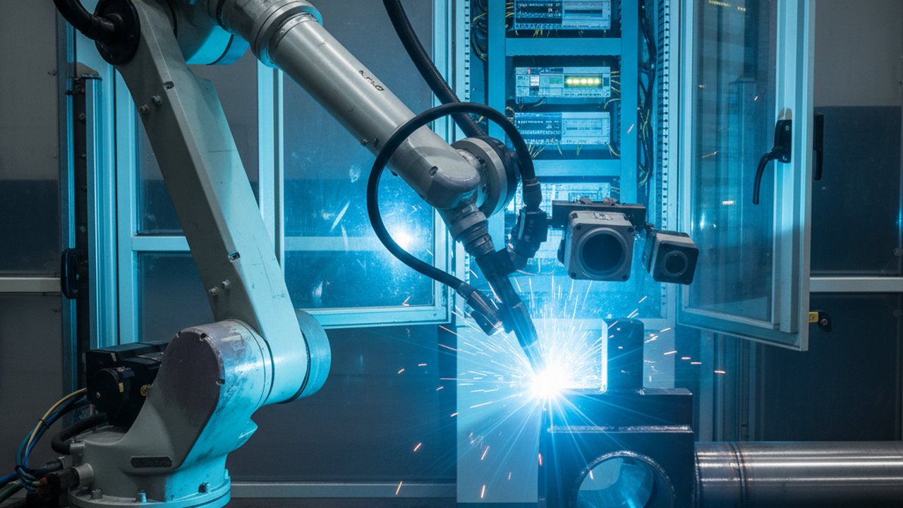
A robotic welding cell already produces every signal a monitoring system needs — it just produces them from four different places, on four different clocks, none of which was designed to talk to the others. The torch-mounted or cell-fixed camera sees the pool. The thermal camera sees the heat field around it. The power source reports voltage, current and wire feed speed as electrical values. The PLC or robot controller knows where the torch actually is on the joint and which program step is running. A monitoring system that only reads one of these answers only one of the questions a per-weld record needs answered — and a system that reads all four but never aligns them to the same point on the weld path produces four separate logs, not one record.
This article walks through where each signal actually comes from inside the cell, what it is good for on its own, and what “aligned to the weld path” means in practice: not four data streams sharing a folder, but four readings tied to the same joint, the same pass, and the same moment the torch was there.
Key takeaways
- Robotic weld monitoring draws from four physically distinct sources: the visual camera on the pool, the thermal camera on the surrounding field, the power source’s electrical signals, and the PLC or robot controller’s position and program state.
- A torch-mounted camera tracks the pool through every joint orientation the robot reaches; a cell-fixed camera avoids added wrist payload but can be occluded at some angles.
- The power source’s voltage and current signals are often the earliest evidence of a process fault, ahead of any change a camera can see.
- Without the PLC or robot controller’s position feed, every other signal is a value with no location on the seam.
- Alignment is a synchronisation problem — a shared trigger or timestamp — not a matter of collecting more data.
- The output that matters is a per-weld record: one entry per seam segment, not four parallel logs a person has to reconcile by hand.
Source 1 — the camera on the weld pool
The visual camera is usually the signal people picture first, and it is mounted one of two ways.
A torch-mounted camera travels with the torch, so the pool stays centred in the frame through every joint angle the robot’s program calls for — the same reason seam-tracking systems put their camera here. The cost is mechanical: extra payload on the robot wrist and a dress-pack that has to route camera cable alongside torch cable without adding drag or interference through the whole reach envelope.
A cell-fixed camera sits on a bracket outside the robot’s moving mass, so it adds no wrist payload and no dress-pack routing. The trade is line of sight: at some joint orientations the robot arm, the part fixture, or the torch body itself can sit between the camera and the pool, so a fixed camera’s coverage has to be checked against the actual program, not assumed from the layout drawing.
Either way, what the camera is built to survive matters as much as where it sits: arc radiance, spatter, and heat all shorten the working life of anything not specifically rated for the environment directly in front of a welding arc.
Source 2 — the thermal camera on the heat field
A thermal camera answers a different question than the visual camera does. Where the pool camera shows shape and motion at the arc, the thermal camera reads the temperature field around and behind it — the heat that has already been deposited, cooling on the already-welded length of the joint. That is the signal interpass temperature checks and cooling-rate trends are built from, and it is present whether or not the arc is currently on.
Mounting follows the same torch-mounted-or-fixed choice as the visual camera, with the same trade-offs, though a thermal unit reading a wider field of view around the joint tolerates a fixed position better than a pool-centred visual camera does. HeatCam IR-C is built for this role in a robotic cell: continuous thermal read of the joint and surrounding parent material, independent of the visual feed. The reason this signal is worth wiring up at all is timing: thermal video shows several defect mechanisms forming before they are visible any other way, which is exactly the lead time a robotic cell needs to act on a fault before the next part loads.
Source 3 — the power source’s electrical signals
The power source is the signal source people most often forget is already there. Many modern inverter power sources can expose arc voltage, welding current and wire feed speed over a data interface, so on those cells the signal is a connection away. Where the source has no such interface, or where the record has to show what was actually delivered rather than what the source reports, an independent acquisition unit reads the same quantities at the cable.
This matters because an electrical signature often moves before a camera would show anything. A shielding-gas dropout, a worn contact tip, or a wire feed speed stumble shows up as a voltage or current excursion frequently ahead of any visible pool disturbance, simply because the arc’s electrical behaviour reacts to the fault mechanism directly, while a camera is reading a downstream visual consequence of it. WeldTrace acquires voltage, current and wire feed speed together fast enough to resolve that kind of transient, with shielding-gas flow logged alongside them on the same pass.
Source 4 — the PLC and robot controller
The fourth source is the one that turns the other three from values into evidence: the PLC or robot controller, which is the only place in the cell that knows where the torch actually is on the joint, which program step is running, and when the arc is enabled or disabled.
A voltage reading, a thermal frame, or a pool image without a position attached to it is a number, not a record. The PLC’s position and arc-state feed is what lets every other signal be assigned to a specific joint, pass, and length of seam instead of sitting in a log with a timestamp and nothing else.
This is also usually the least glamorous integration in the cell, and the most load-bearing: robot-agnostic monitoring has to read this feed correctly across the different robot controller families, each with its own way of exposing arc-on/arc-off state and joint position to an external system.
Why alignment, not collection, is the actual problem
Four sources producing four streams of data is not, on its own, a monitoring system. Each stream runs on its own clock: the camera frames at its own frame rate, the thermal unit at its own refresh interval, the power source at whatever sampling rate its interface supports, and the controller emitting position and state changes as the program executes. None of these clocks is naturally synchronised to the others.
Alignment means picking a shared reference and triggering or timestamping every stream against it. In practice that reference is usually the arc-on/arc-off event the power source and controller both already produce, sometimes supplemented by a position tick from the robot program at fixed intervals along the seam. Hardware triggering — the camera capturing exactly when the arc-enable signal fires, rather than free-running on its own clock and being matched up afterward in software — keeps that alignment tight enough to trust; a software-only match introduces timing jitter that can put a signal reading a pass or two away from where it actually happened.
Get this wrong and the failure is invisible until someone tries to use the record: the thermal frame and the voltage reading both exist, both have timestamps, and neither one is provably from the same instant on the same joint.
Building the per-weld record
Once the four sources are aligned to the same weld-path reference, the output is a single per-weld record rather than four logs: the WPS and welder or program reference, the joint position and pass number from the controller, the electrical trace from the power source for that segment, the thermal and visual read for the same segment, and a pass/fail flag with a stated reason.
This is the same structure a manually kept weld map already uses — welds identified, WPS and welder assigned, coverage tracked per weld — populated from the cell’s own signals instead of typed in after the fact. A record built this way fits within the quality records ISO 3834-2 requires of a fusion-welding fabricator, alongside the inspection and testing records already kept; it does not replace them, and it does not remove the acceptance criteria a fabricator still applies from the relevant product or examination standard.
Common alignment failures and fixes
- The camera free-runs on its own clock. Frames exist but cannot be matched to a specific pass with confidence. Fix: hardware-trigger capture off the arc-enable or arc-detect signal rather than polling on a timer.
- The thermal read has no position tag. A temperature trend exists but nobody can say which length of the joint it covers. Fix: log the controller’s position feed alongside every thermal sample, not just at the start and end of the pass.
- The power source’s signals are read at too coarse an interval. A brief current dip that lasted a fraction of a second gets averaged away before it is logged. Fix: sample at a rate that can resolve the shortest fault duration relevant to the process, not the rate that happens to be convenient for the existing data logger.
- The PLC feed is treated as optional. Camera and thermal data get collected, but without joint position they cannot be assigned to a specific weld. Fix: treat the position and arc-state feed as a required input to the record, not an enrichment added later.
- Four systems, four separate exports. An inspector has to open four files and manually match timestamps to check one weld. Fix: merge the streams into one per-weld record at the point of capture, not at audit time.
Where this fits with the ROI case
None of the above changes the economics on its own; wiring up four signals and aligning them costs integration time regardless of what it finds. The ROI case for robotic arc welding monitoring covers the other side of that ledger: what a per-weld record is worth once it exists, in rework avoided and inspection time saved, separate from the question of how the signal gets built in the first place.
HeatCore AI is the layer that scores the aligned signal in real time, once the four sources above are wired to a common weld-path reference — the scoring is only as good as the alignment underneath it, which is the part this article has been about.
FAQ
What are the main signal sources for weld monitoring in a robotic welding cell? Four, typically: a torch-mounted or cell-fixed visual camera on the pool, a thermal camera reading the surrounding heat field, the power source reporting arc voltage, current and wire feed speed, and the PLC or robot controller reporting joint position, program step and arc-on/arc-off state.
Should the visual camera be mounted on the torch or fixed in the cell? It depends on what the camera has to see. A torch-mounted camera keeps the pool centred through every joint orientation the robot reaches, which suits seam tracking and per-pass pool geometry, at the cost of added wrist payload and dress-pack routing. A cell-fixed camera avoids that kinematic load and suits interpass thermal views or post-weld checks, but the robot or part can occlude it at some joint angles. Many cells use both.
What does a thermal camera add that a visual camera on the pool does not? The visual camera shows pool shape and arc behaviour; the thermal camera shows the heat field around and behind the pool, including interpass temperature and cooling trend on already-deposited passes. The two answer different questions and neither substitutes for the other.
What signals come from the power source itself, and why do they matter? Modern inverter power sources carry arc voltage, welding current and wire feed speed as electrical signals. A deviation usually shows up there before the camera sees it. A current or voltage excursion is often the earliest evidence of a shielding-gas fault, a contact-tip problem or a wire-feed stumble, ahead of any visible pool change.
Why does the PLC or robot controller need to be part of the monitoring chain? The PLC and robot controller are the only source for where the torch actually is on the weld path and which program step is running. Without that position and state feed, every other signal is a value with no location: a temperature spike or a voltage dip cannot be tied to a specific joint, pass or seam length.
How are camera, thermal, power-source and PLC signals aligned to the same point on the weld path? By a shared reference the robot program already produces: arc-on and arc-off events, or a position tick from the controller, used as a common clock that every signal stream is timestamped or triggered against. Alignment is a synchronisation problem, not a data-volume problem, and it has to be solved before any signal is trusted as evidence for a specific weld.
What does a per-weld record built from these signals actually contain? One entry per weld or per seam segment, carrying the WPS and welder or program reference, the joint position from the robot program, the process trace from the power source, the thermal and visual read for that segment, and a pass or fail flag with the reason. It is the same structure a weld map already uses, populated automatically instead of by hand.
Does adding these monitoring signals slow the robot cycle down? Not when it is wired correctly. Camera and thermal capture and power-source logging run in parallel with welding, triggered off signals the controller already generates, and add no dwell time of their own. What does cost cycle time is a system that stops the robot to poll a sensor instead of listening to what is already running.
See where your cell's signals actually come from
Therness aligns the torch camera, thermal camera, power source and PLC feed to one weld-path reference, so every seam gets one per-weld record instead of four logs to reconcile by hand.
Talk to an engineerTherness solution: Welding monitoring system — Every weld inspected in the cycle, with defect flags and the ISO 3834 / ISO 17635 evidence kept per weld.
Frequently Asked Questions
What are the main signal sources for weld monitoring in a robotic welding cell?
Four, typically: a torch-mounted or cell-fixed visual camera on the pool, a thermal camera reading the surrounding heat field, the power source reporting arc voltage, current and wire feed speed, and the PLC or robot controller reporting joint position, program step and arc-on/arc-off state.
Should the visual camera be mounted on the torch or fixed in the cell?
It depends on what the camera has to see. A torch-mounted camera keeps the pool centred through every joint orientation the robot reaches, which suits seam tracking and per-pass pool geometry, at the cost of added wrist payload and dress-pack routing. A cell-fixed camera avoids that kinematic load and suits interpass thermal views or post-weld checks, but the robot or part can occlude it at some joint angles. Many cells use both.
What does a thermal camera add that a visual camera on the pool does not?
The visual camera shows pool shape and arc behaviour; the thermal camera shows the heat field around and behind the pool, including interpass temperature and cooling trend on already-deposited passes. The two answer different questions and neither substitutes for the other.
What signals come from the power source itself, and why do they matter?
Modern inverter power sources carry arc voltage, welding current and wire feed speed as electrical signals. A deviation usually shows up there before the camera sees it. A current or voltage excursion is often the earliest evidence of a shielding-gas fault, a contact-tip problem or a wire-feed stumble, ahead of any visible pool change.
Why does the PLC or robot controller need to be part of the monitoring chain?
The PLC and robot controller are the only source for where the torch actually is on the weld path and which program step is running. Without that position and state feed, every other signal is a value with no location: a temperature spike or a voltage dip cannot be tied to a specific joint, pass or seam length.
How are camera, thermal, power-source and PLC signals aligned to the same point on the weld path?
By a shared reference the robot program already produces: arc-on and arc-off events, or a position tick from the controller, used as a common clock that every signal stream is timestamped or triggered against. Alignment is a synchronisation problem, not a data-volume problem, and it has to be solved before any signal is trusted as evidence for a specific weld.
What does a per-weld record built from these signals actually contain?
One entry per weld or per seam segment, carrying the WPS and welder or program reference, the joint position from the robot program, the process trace from the power source, the thermal and visual read for that segment, and a pass or fail flag with the reason. It is the same structure a weld map already uses, populated automatically instead of by hand.
Does adding these monitoring signals slow the robot cycle down?
Not when it is wired correctly. Camera and thermal capture and power-source logging run in parallel with welding, triggered off signals the controller already generates, and add no dwell time of their own. What does cost cycle time is a system that stops the robot to poll a sensor instead of listening to what is already running.