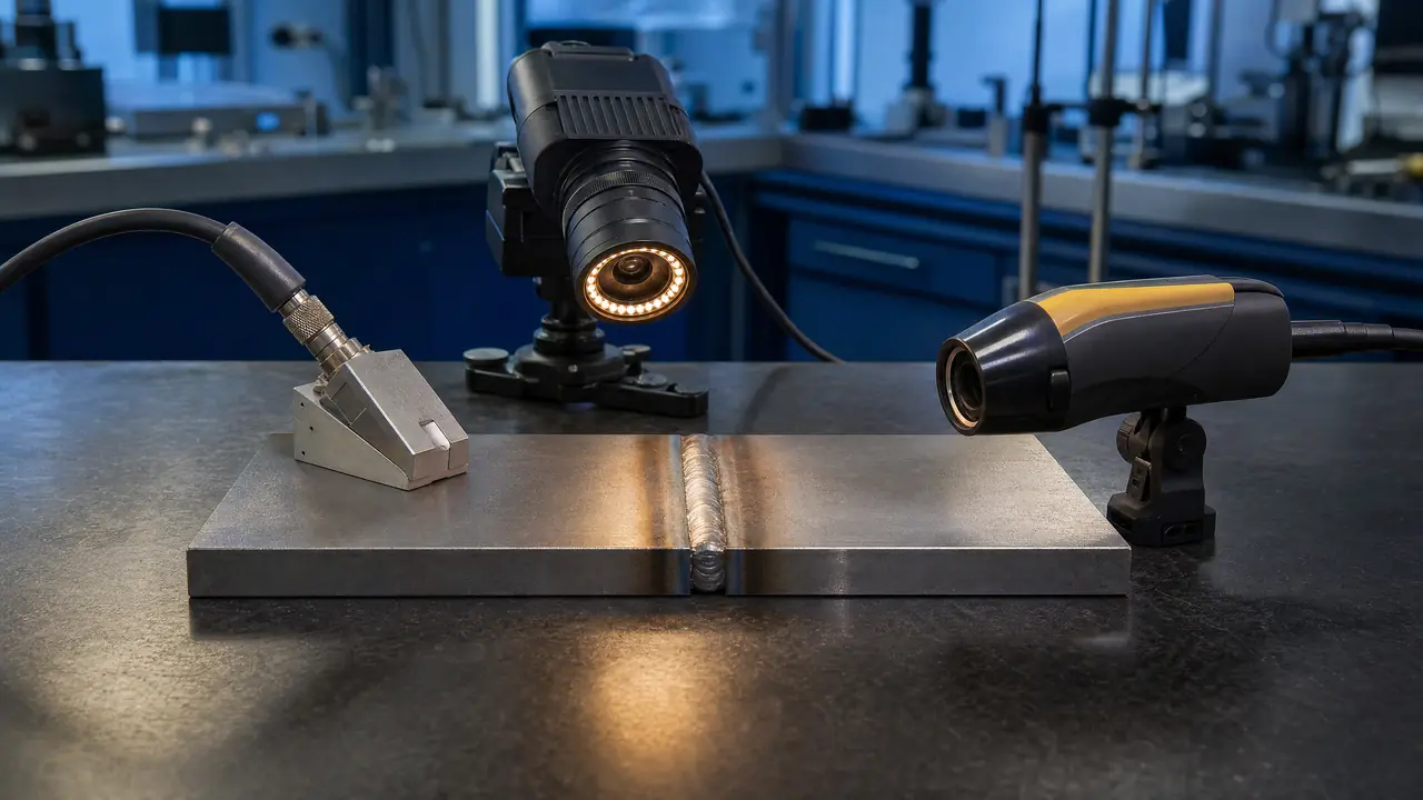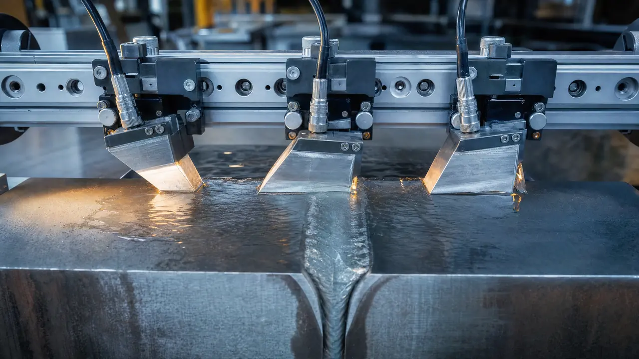
When a weld inspection specification leaves the choice of NDT method open, active thermography and radiography often end up on the same shortlist. Both generate an image of the weld, both detect subsurface defects, and both satisfy most Level 2 quality requirements under EN ISO 3834 or ISO 9001. But the physics, practical constraints, and defect sensitivity of each method are fundamentally different. Choosing the wrong one costs time, money, or — worse — missed defects. This guide maps the key decision factors so you can select the right technique for each inspection scenario.
The Physics in Two Paragraphs
Radiography passes ionising radiation — X-rays or gamma rays — through the weld. Density variations caused by voids (porosity, lack of fusion, cracks) attenuate the beam differently from solid metal, producing contrast on a film or digital detector. The technique is inherently volumetric: it integrates information through the full thickness of the part. EN ISO 17636-1 (film) and EN ISO 17636-2 (computed radiography and digital detector arrays) govern technique selection, geometry, and image quality.
Active thermography injects a thermal pulse or periodic heat wave into the component surface — via flash lamps, halogen heaters, or induction coils — and records the transient thermal response with an infrared camera. Subsurface defects act as thermal barriers: they slow or divert heat flow, creating detectable temperature anomalies at the surface. EN 16714 governs the method; personnel qualify to ISO 9712 in the thermographic testing (TT) method.
Both methods require a written inspection procedure approved by a Level 3 NDT engineer qualified to the relevant method under ISO 9712.
Defect Detection: What Each Method Sees
The most important difference between the two techniques is defect orientation sensitivity.
| Defect type | Radiography (RT) | Active thermography (AT) |
|---|---|---|
| Internal porosity | Excellent (high contrast) | Poor (volume too small for thermal barrier) |
| Slag / tungsten inclusions | Excellent | Poor |
| Lack of fusion (volumetric gap) | Good | Good — if near surface |
| Transverse cracks | Poor (perpendicular to beam) | Good (thermal barrier regardless of orientation) |
| Longitudinal cracks | Good (parallel to beam) | Good |
| Delaminations / lack of bond | Poor | Excellent |
| Surface-breaking cracks | Poor | Good (via induction thermography) |
| Undercut / geometric defects | Visible on profile | Visible on surface map |
| Weld root defects (>5 mm depth) | Excellent | Limited by depth sensitivity |
The key insight: RT images density contrasts; AT images heat-flow barriers. This means RT wins for volumetric embedded defects in thick sections, while AT wins for planar defects and wide-area surface/near-surface screening. (Watch a thermal imaging weld comparison that shows the heat-flow contrast in action.)
A delamination in a 3 mm stainless steel clad plate presents near-zero radiographic contrast — the gap is too thin to attenuate X-rays measurably. The same defect appears with high contrast in a lock-in thermography scan because it interrupts lateral heat diffusion across the full clad area.
Standards and Regulatory Requirements
Radiography: EN ISO 17636
EN ISO 17636 is the reference standard for radiographic testing of fusion-welded joints in metallic materials. It specifies:
- Class A (basic technique) and Class B (improved technique) with different sensitivity requirements
- Source-to-film distance, geometric unsharpness limits, and image quality indicator (IQI) requirements
- Film and digital detector selection by material thickness and weld geometry
- Acceptance criteria are referenced separately — typically EN ISO 5817 (steel welds) or the applicable product standard
EN ISO 17636 applies across pressure vessels (EN 13445), structural steelwork (EN 1090), and railway (EN 15085). Many codes — ASME Section V Article 2, API 1104 — mandate radiography by name, leaving no method choice.
Active Thermography: EN 16714
EN 16714 is structured to mirror conventional NDT standards:
- EN 16714-1: General principles — procedure qualification, personnel qualification, report content
- EN 16714-2: Equipment — IR camera NETD (<50 mK), spatial resolution, calibration requirements, excitation source specifications
- EN 16714-3: Terms and definitions
Where a code specifies “radiographic or equivalent thermographic testing”, EN 16714-compliant active thermography is typically accepted after procedure qualification demonstrating equivalent defect detectability. This is increasingly common for thin-wall automotive structural welds, aerospace bond-line inspection, and rail vehicle bogie frames under EN 15085. Therness delivers weld inspection built to these EN 16714 procedures.
For details on how the method meets EN 16714 requirements across different industrial sectors, see what the standards actually require, sector by sector.
Operational Comparison
Beyond physics and standards, operational constraints frequently decide the method:
| Factor | Radiography | Active thermography |
|---|---|---|
| Radiation safety | Exclusion zone required; RPO supervision; regulatory licensing | No ionising radiation; no exclusion zone |
| Production interruption | High — area must be evacuated during exposure | Low — single operator, no area clearance |
| Inspection speed | 1 film = ~1 weld seam; setup + exposure + development: 15–45 min | 0.5–2 m²/min scan rate; real-time display |
| Portability | X-ray tube or gamma source: heavy, requires transport permits for isotopes | Compact IR camera + portable excitation head |
| Surface access | Needs both-side access for source + detector | Single-side access sufficient for most techniques |
| Material thickness | Optimal 5–150 mm (X-ray); unlimited (gamma, with power) | Best results <15 mm; reduced sensitivity >20 mm |
| Consumables | Film or digital plates; processing chemistry | None |
| Data archiving | Radiograph (film or digital file) | Thermogram sequence (data cube) |
Gamma radiography with Ir-192 or Se-75 sources requires a radiation protection supervisor (RPS) on site and transport authorisation under ADR/IATA. This is a significant operational overhead on live construction sites or offshore platforms.
Decision Framework: Which Method for Which Scenario
Use this matrix as a starting point. Override with your applicable code if it mandates a specific method.
Use radiography when:
- The applicable code mandates RT (ASME B31.3, API 1104 critical pipeline, pressure vessel DNV rules)
- Weld thickness >20 mm and volumetric defects are the primary concern
- You need depth localisation of embedded porosity or inclusions for repair scoping
- EN ISO 5817 Level B acceptance criteria apply and client requires radiographic records as quality evidence
Use active thermography when:
- Radiation exclusion zones are operationally unacceptable (live production lines, occupied structures)
- Inspection area is large and speed matters — post-weld screening of structural assemblies, rail vehicles, pressure vessels before final closure
- Primary concern is delaminations, lack of bond in clad/overlay welds, or surface-breaking cracks
- Thin-wall components (<10 mm) where AT achieves comparable sensitivity to RT at a fraction of the cost
- Digital output is required for integration with a quality management system or AI-based defect classification
Use both (complementary approach):
- Phase 1: AT screening of the full weld map → flag anomaly zones
- Phase 2: RT on flagged zones for volumetric characterisation and depth measurement
- Result: full coverage at lower radiation dose and inspection cost than 100% RT
This tiered strategy is recognised in EN ISO 3834-2 (comprehensive quality requirements) and is increasingly adopted by Tier 1 automotive and aerospace suppliers managing large weld seam volumes under AIAG CQI-15 audit requirements.
Key Technical Limitations to Know
Active thermography depth limit. Thermal diffusion is frequency-dependent: the thermal diffusion length δ = √(D/πf), where D is thermal diffusivity and f is excitation frequency. For structural steel (D ≈ 12 × 10⁻⁶ m²/s), lock-in thermography at 0.1 Hz reaches δ ≈ 6 mm. Pulsed thermography typically resolves defects to 3–5 mm depth in steels. Defects >10–15 mm deep are generally below the reliable detection threshold.
Radiography geometric limitations. Defects perpendicular to the radiation beam — planar cracks parallel to the film — present minimal contrast. EN ISO 17636 requires multiple exposure angles for complex geometries precisely because of this limitation. Active thermography has no equivalent geometric dependency.
EN ISO 5817 acceptance criteria. Both methods must ultimately be evaluated against the same acceptance criteria. However, RT provides direct dimensional measurement of defect length and area from the radiograph. Active thermography provides a temperature contrast map: defect sizing requires calibrated reference standards and a validated procedure before results can be cited against EN ISO 5817 limits.
Summary
Active thermography and radiography are complementary, not competing, NDT methods. RT remains the required method where codes mandate it and for deep volumetric defect characterisation. AT delivers faster, radiation-free wide-area inspection with superior sensitivity to planar and near-surface defects. The fastest-growing application is the tiered model: AT for full-area screening, RT for targeted investigation of AT-flagged zones. To match hardware to your weld map, browse the inspection systems.
For a deeper look at the different excitation techniques — pulsed, lock-in, flash, and induction — see which one suits your defect catalogue.
See Active Thermography in Action on Your Weld Line
Therness HeatCam systems deliver real-time thermographic weld inspection. Book a demo to see detection performance on your specific weld geometry and material.
Book a demoTherness solution: Welding monitoring system — Every weld inspected in the cycle, with defect flags and the ISO 3834 / ISO 17635 evidence kept per weld.
Frequently Asked Questions
Can active thermography replace radiography for weld inspection?
Active thermography cannot fully replace radiography for all weld inspection tasks. Radiography excels at detecting volumetric embedded defects — internal porosity, slag inclusions, and lack of fusion — in thick-section butt welds, especially where EN ISO 17636-2 (digital radiography) is the specified examination method. Active thermography is superior for wide-area surface and near-surface inspection, delaminations in thin-wall or overlay welds, and any situation where ionising radiation is impractical. The two methods are often used together: thermography for fast screening, radiography for volumetric characterisation of suspect zones.
What defects can active thermography detect that radiography cannot?
Active thermography is more sensitive than radiography to planar defects oriented parallel to the inspection surface — delaminations, lack of bond in clad plates, and shallow fatigue cracks. These defects present little radiographic contrast because they are perpendicular to the X-ray beam. Thermography detects them as thermal barriers (zones with reduced heat diffusivity) regardless of orientation. Radiography, by contrast, detects defects with measurable volume (porosity, inclusions) most effectively when the beam is parallel to the defect plane.
Which standard covers active thermography for weld inspection?
EN 16714 (Thermographic testing) is the primary European standard for active thermography NDT, structured in EN 16714-1 (general principles), EN 16714-2 (equipment), and EN 16714-3 (terms). Personnel qualification follows ISO 9712 (thermographic testing method, Levels 1–3). Radiographic testing of fusion welds is governed by EN ISO 17636-1 (film radiography) and EN ISO 17636-2 (digital radiography). Both methods require written procedures approved by a Level 3 NDT engineer qualified in the relevant method.