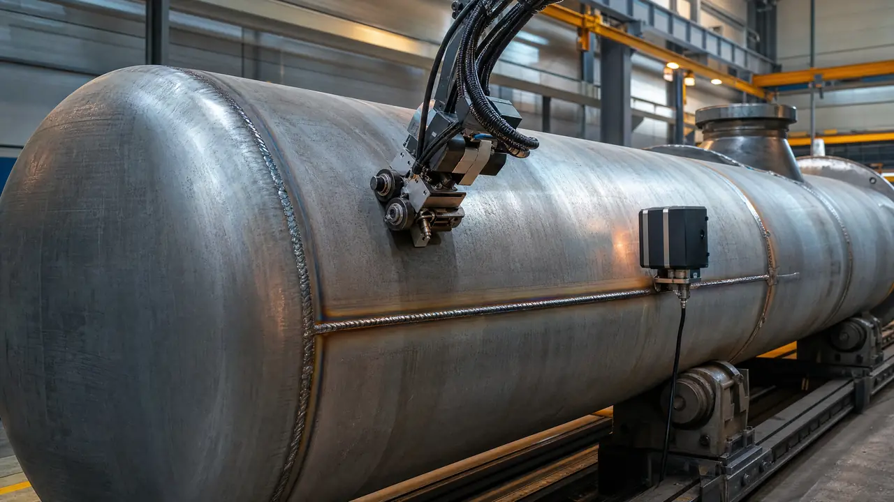
ASME Section VIII and ASME Section IX get confused constantly because they are both part of the same Boiler and Pressure Vessel Code (BPVC) and both show up on the same fabrication drawing package — but they answer completely different questions. Section VIII, Division 1 sets the rules for constructing a pressure vessel: materials, design, fabrication, examination, and acceptance for the finished vessel. Section IX qualifies the welding procedures and welders used to build it — a separate, prerequisite step that Section VIII references rather than restates. A shop can hold a perfectly qualified Section IX procedure and welder roster and still fail a Section VIII audit if the vessel’s design, examination, or documentation does not meet Division 1’s own construction requirements, and the reverse is equally true.
This guide covers welding, NDE, and acceptance requirements under the current ASME BPVC Section VIII, Division 1 (2025 edition), issued on ASME’s standard biennial BPVC revision cycle. Every edition-dependent requirement below names the 2025 edition explicitly, because Division 1 is revised on that cycle and a requirement correct in one edition can shift in the next.
Scope: what makes a vessel a Division 1 vessel
Section VIII, Division 1 provides requirements applicable to the design, fabrication, inspection, testing, and certification of pressure vessels operating at internal or external pressures exceeding 15 psig. It is the most widely used of the three Section VIII divisions — Division 2 (Alternative Rules) permits higher design stresses with correspondingly more rigorous design analysis and examination, and Division 3 covers very high-pressure vessels outside Division 1’s scope entirely. A fabricator choosing between Division 1 and Division 2 for a given vessel is trading Division 1’s simpler, more conservative rules against Division 2’s higher allowable stress and correspondingly higher analysis and examination burden — a design and cost decision made well before welding starts, not a welding-procedure decision.
Welding procedure qualification under Section IX
Every weld on a Division 1 vessel is made to a Welding Procedure Specification (WPS) qualified per Section IX, using welders or welding operators who hold current Section IX Welder Performance Qualification (WPQ) for the specific process, position, and material combination the vessel requires. Division 1 itself does not restate Section IX’s qualification variables — essential variables, supplementary essential variables where impact testing applies, and the ranges each qualification covers — it simply requires that qualification exist and that the production weld fall within the qualified ranges. An inspector reviewing vessel welding records checks the WPS against its supporting Procedure Qualification Record (PQR) and confirms the production joint’s actual parameters — material, thickness, process, position — sit inside what the PQR actually qualified, not just that a PQR exists somewhere in the file.
Joint categories and efficiency factors
Division 1 organizes vessel welded joints into categories (commonly labelled A, B, C, and D) based on the joint’s location and orientation on the vessel — Category A joints, for example, are the longitudinal joints in the main shell and heads, generally the highest-stressed and most consequential category. Each category carries its own set of permitted joint types and, critically, its own joint efficiency factor — a value between a fraction and 1.0 that derates the allowable stress in the design calculation to account for the joint’s examination level. A fully radiographed Category A joint carries a higher efficiency factor than the same joint type examined only by spot radiography, which is the code’s way of directly trading examination extent against how much stress the design is allowed to put through that joint. Because the exact efficiency factor values are tabulated by joint type and examination level in the current edition, this guide does not restate them as standalone figures — a design calculation pulls the applicable factor from the 2025 edition’s own table for the specific joint category and examination level the vessel actually receives.
The other joint categories
Category A is the highest-consequence category, but Division 1 defines the full set. Category B joints are typically the circumferential joints connecting shell sections to each other or to heads, and to transitions in shell diameter or thickness. Category C joints connect flanges, tubesheets, and flat heads to the shell or head they attach to. Category D joints connect nozzles, communicating chambers, and other openings to the shell, head, or flat plate they penetrate. Each category carries its own set of permitted joint types and its own examination-versus-efficiency trade-off, structured the same way as Category A but calibrated to that category’s typical stress state and consequence of failure. A vessel’s design drawing identifies every welded joint by category before fabrication starts, precisely so that the correct examination extent and efficiency factor are locked in at the design stage rather than negotiated after the vessel is already welded.
NDE method selection
Division 1 specifies which combination of visual, radiographic, ultrasonic, magnetic particle, and liquid penetrant examination applies to a given joint category, material, and service — and, tied directly to the joint efficiency discussion above, at what extent (full radiography, spot radiography, or none, subject to the corresponding efficiency factor). Radiographic testing under the ISO, ASME, and API frameworks covers how RT acceptance criteria are structured across these codes and where Division 1’s own criteria sit relative to ISO 5817 or API 1104 for a fabricator working across more than one code system on adjacent equipment. As with every ASME construction code covered on this site, Division 1 does not leave method or extent to the fabricator’s preference — the applicable table, keyed to joint category and service, determines it, and the ITP records which cell of that table applies to each joint.
Post-weld heat treatment
Division 1 mandates PWHT for material and thickness combinations the code’s own PWHT table specifies, following the same structure as the other ASME construction codes: a minimum holding temperature range and minimum holding time by material (P-Number) and nominal thickness, with additional considerations for vessels in specific services (such as those requiring impact testing at low design temperatures) that can trigger PWHT even where thickness alone would not. Thermal monitoring through the PWHT cycle is how a fabricator produces a continuous, auditable temperature record for the heating ramp, hold, and controlled cooldown, rather than relying on a single thermocouple reading logged at the start and end of the cycle — a continuous trace shows whether the entire vessel wall reached and held the required temperature range, not just the point the thermocouple happened to be attached to.
Hydrostatic testing
Before a Division 1 vessel enters service, it undergoes a pressure test — hydrostatic in the great majority of cases, pneumatic only where the code’s more restrictive conditions for a pneumatic test are met and documented. The required test pressure is calculated as a specified multiple of the vessel’s design pressure under UG-99, adjusted by the ratio of the material’s allowable stress at test temperature to its allowable stress at design temperature — the exact multiplier and the full calculation are set out in UG-99 of the current edition rather than restated here as a bare number, because the ratio adjustment means the effective test pressure is vessel- and material-specific even when the nominal multiplier is the same across vessels. The test record — medium, pressure achieved and held, hold duration, and confirmation of no leakage or permanent deformation — becomes part of the vessel’s permanent documentation package alongside its welding, examination, and PWHT records.
Building the quality evidence trail
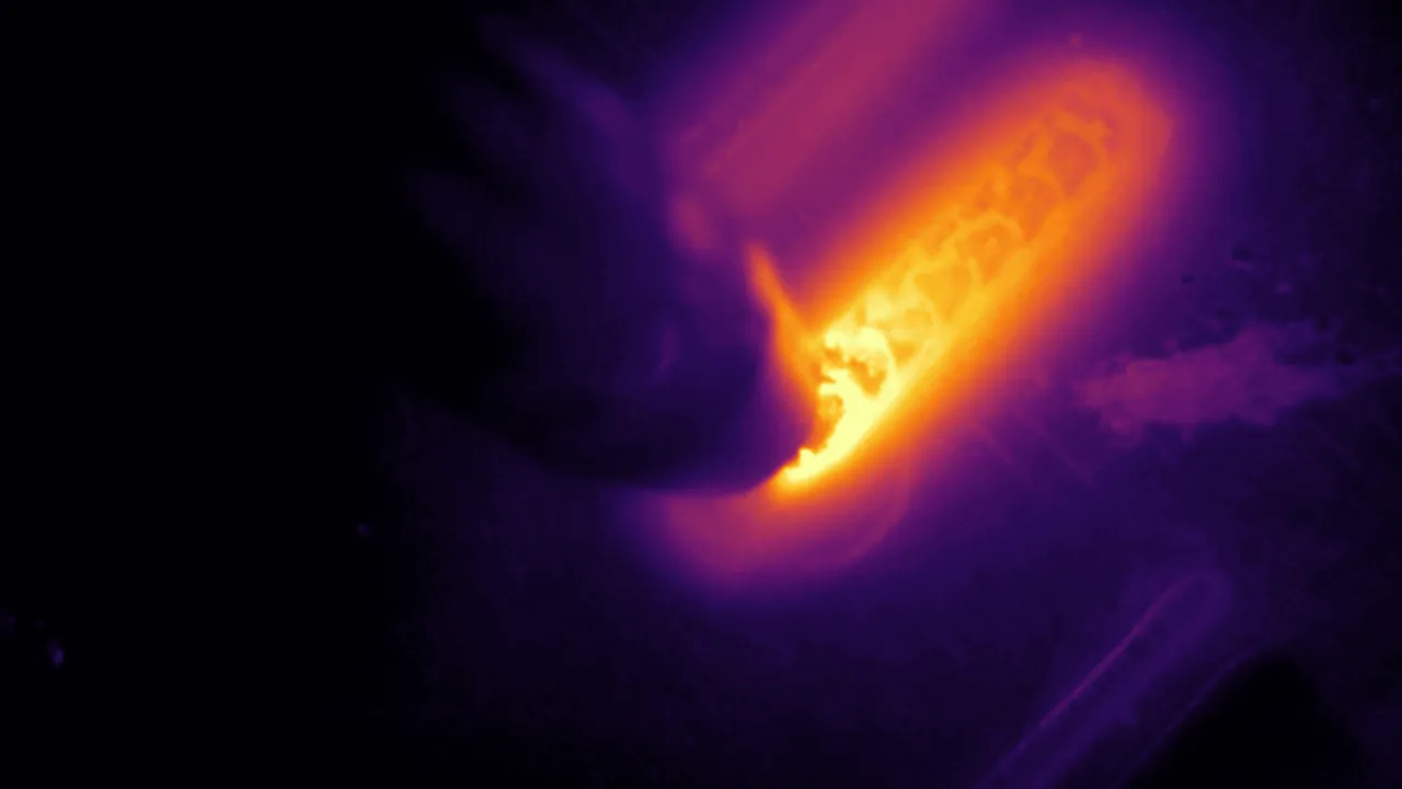
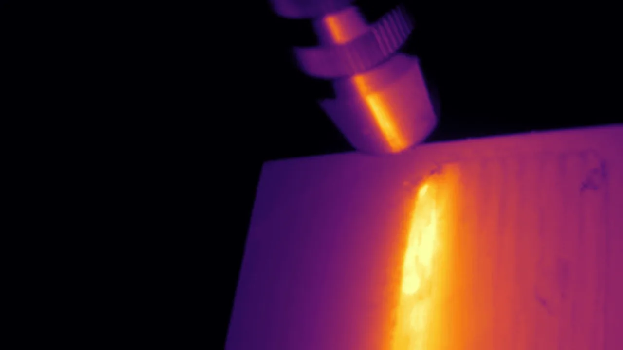
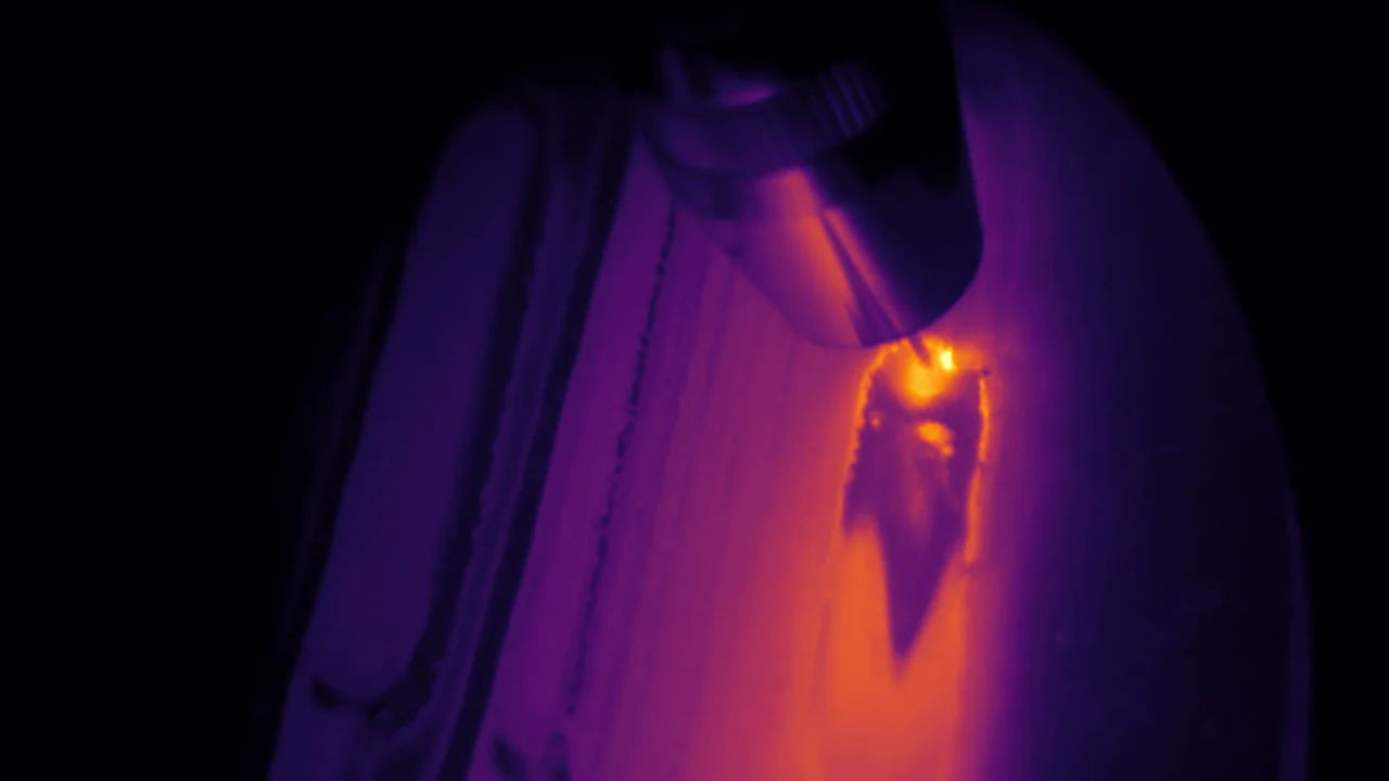
ISO 3834 and PED-aligned quality monitoring for pressure vessel fabrication covers how a shop building to both the ASME framework and the European Pressure Equipment Directive can run one quality system that satisfies both sets of documentation requirements rather than maintaining two parallel paper trails. Within either framework, a welding monitoring system that records process parameters and thermal behaviour continuously during welding and PWHT adds a corroborating evidence layer — not a substitute for the Section IX qualification, the Division 1 examination results, or the hydrostatic test record, but a joint-by-joint process record that supports the case that the qualified procedure was actually followed in production, not just qualified once in a test coupon.
What this guide does not claim
This guide does not state or imply that any product, monitoring system, or vendor described on this site carries U-stamp eligibility or ASME certification of any kind. U-stamp authorization is a facility-level ASME accreditation covering a fabricator’s quality system, not a property of a monitoring instrument, and Therness holds no ASME certification and makes no claim to. Any vessel fabricator’s own U-stamp status and Quality Control System are matters for that fabricator’s own ASME accreditation records, entirely separate from whatever in-process monitoring equipment that fabricator chooses to use on the shop floor.
Practical scoping checklist
Before welding starts on a Division 1 vessel: confirm the vessel is correctly scoped under Division 1 rather than Division 2 or Division 3 based on its actual design pressure and stress requirements; qualify WPS and welders under Section IX for the specific process, material, and position combinations the vessel design calls for; determine each joint’s category and, from the design’s required joint efficiency, the examination extent that efficiency depends on; and confirm PWHT and hydrostatic test requirements from the current 2025 edition’s own tables for the vessel’s actual material and thickness, rather than carrying forward values from a previous vessel built to an earlier edition. Documented correctly, the finished package traces every joint back to its Section IX qualification, its Division 1 examination result, and — where the fabricator runs one — its in-process monitoring record, so that an inspector reviewing the vessel years into service can reconstruct exactly how it was qualified to be built and how it was verified to have been built that way.
The Authorized Inspector’s role
Division 1 vessel fabrication under the ASME Code stamp involves a party the code itself defines: the Authorized Inspector (AI), employed by an ASME-accredited inspection agency independent of the fabricator, who reviews design calculations, witnesses required examinations and the hydrostatic test, and signs the Manufacturer’s Data Report before the vessel is stamped and released. The AI’s review is not a duplicate of the fabricator’s own quality control — it is an independent check that the fabricator’s Quality Control System, the specific vessel’s documentation, and the examination results actually support the certification being made. A fabricator’s internal QC records, welding records, and in-process monitoring data all feed into what the AI reviews, but the AI’s sign-off is a distinct step in the chain, not a formality layered on top of a fabricator’s self-certification.
Repair and rework of rejected welds
A vessel weld that fails examination against Division 1’s acceptance criteria follows the same general repair logic as other ASME construction codes: repair under a qualified procedure — the original WPS if its qualified range covers the repair, or a repair-specific WPS if it does not — followed by re-examination of the repaired area at the same method and extent the original joint required, evaluated against the same acceptance criteria. The repair and its re-examination result both need to appear in the vessel’s permanent record, identified against the specific joint location, so that a later review can distinguish a joint that was correctly repaired and re-verified from one where a reject was simply reworked without adequate follow-up examination.
Because a pressure vessel’s design calculation depends on the actual joint efficiency achieved, a repair that changes the examination method or extent applied to a joint — for example, a joint originally spot-radiographed that requires full radiography after repair — can change which joint efficiency factor applies to that joint going forward, and the vessel’s design documentation needs to reflect whichever efficiency the as-built, as-repaired joint actually supports.
Where Section VIII and Section IX responsibilities get confused
The most common confusion is treating a valid Section IX qualification as sufficient evidence that a specific production weld meets Division 1’s requirements. Section IX qualification establishes that a WPS, executed by a qualified welder, produces sound welds within the range of essential variables tested — it says nothing about whether that WPS was actually followed on a specific joint, whether the joint received the examination Division 1’s joint category and service require, or whether the resulting joint efficiency supports the vessel’s design pressure. A shop with an impeccable Section IX qualification file can still fail a Division 1 audit if production records cannot show that the qualified procedure was actually the one used, in its qualified range, on the joint being reviewed — which is exactly the gap continuous parameter and thermal monitoring during production welding is positioned to close, by tying the process record to the specific joint rather than to the procedure’s qualification test coupon alone.
Documentation retention
A Division 1 vessel’s Manufacturer’s Data Report, design calculations, material certifications, welding qualification records, examination results, and hydrostatic test record together form the vessel’s permanent file, retained for the vessel’s operating life rather than a fixed statutory period in most jurisdictions, because an in-service inspection, a repair, or an incident investigation years or decades after fabrication may need to trace back to the original construction records for the specific joint or material heat involved. A digital record system that links in-process monitoring data to specific joint identifiers, alongside the qualification and examination documentation the code requires, makes that retrieval practical at the point in the vessel’s service life when it actually matters — which is rarely soon after fabrication.
See Vessel Welding Process Evidence in Real Time
Therness continuous parameter and thermal monitoring gives pressure vessel fabricators a per-joint process record alongside Section IX qualification and Division 1 examination results. Book a demo to see it on your own vessels.
Book a demoTherness solution: Welding monitoring system — Every weld inspected in the cycle, with defect flags and the ISO 3834 / ISO 17635 evidence kept per weld.