A fillet weld size chart in mm looks like the simplest document in the shop, and it is the one most often read wrong. Two numbers circulate for the same weld — the leg and the throat. They differ by about thirty per cent, both are quoted in millimetres, and nothing in the unit tells them apart. Add a code minimum that exists for metallurgical rather than structural reasons and a designer, a welder and an inspector can each be confident and each be describing a different weld.
Key takeaways
- A fillet weld has two size dimensions in millimetres, leg and effective throat, and a chart that does not say which one it lists is unusable.
- For an equal-leg fillet with a flat face, throat equals leg times 0.707. That factor is geometry, not a code rule.
- Code minimum sizes stop a small bead quenching against a thick section. They are a metallurgical floor, never the structural answer.
- The American codes index the minimum on the thicker part joined; the European family sets a flat throat floor instead. Either way, the required size comes from the load — take whichever is larger.
- Oversize fillets are a real defect class: wasted consumables, added distortion, and a joint outside its qualified procedure range.
- Size is produced by deposition rate and travel speed: controllable upstream, only verified downstream.
What a fillet weld size chart in mm actually lists
Every credible chart is a chart of one dimension. Confusion starts when the heading says only “size”.
Leg length
The leg runs from the joint root along the fusion face to the toe, on each member. It is what a leg gauge reads and the dimension checkable without cutting anything. ISO drawing practice writes it with a leading z.
Effective throat
The throat is the shortest distance from the theoretical root to the weld face. It is the dimension that carries load, because a fillet fails through its throat and not along a leg. ISO practice gives the design throat a leading a.
Why the two are not interchangeable
An a6 and a z6 are different welds. The first asks for a 6 mm throat, needing roughly 8.5 mm legs. The second asks for 6 mm legs, delivering roughly a 4.2 mm throat. Substituting one for the other silently cuts the capacity of the connection by roughly thirty per cent, because fillet capacity runs with throat area, not leg length — the most common error a size chart introduces once it is photocopied out of context. Go the other way, from z6 up to a6, and the weld metal deposited roughly doubles, because volume runs with the leg squared: a cost consequence, not a capacity one, and the two are not the same argument.
Put the convention on the drawing, not in a colleague’s head. The rules that make a and z unambiguous are set by the international welding symbol standard, and a title block naming the edition in force ends the argument.
The geometry behind the numbers
Equal legs and the 0.707 relation
On an ideal fillet with a 90 degree included angle, equal legs and a flat face, the cross-section is a right isosceles triangle. The perpendicular from root to hypotenuse is the leg times the cosine of 45 degrees, 0.7071. A 10 mm leg gives a 7.07 mm throat; a 5 mm throat needs a 7.07 mm leg. Round up for legs, down for throats.
Unequal legs, convexity and penetration
Real welds depart from the ideal in ways that move the number you should trust.
- Unequal legs. The throat is no longer a single-factor conversion; it is derived from both leg values.
- Convexity. A convex face adds metal outside the design triangle. That metal is not counted, and it worsens toe stress concentration.
- Concavity. A concave face removes metal from inside the triangle, so the real throat is smaller than the leg conversion predicts. These welds need a throat gauge.
- Deep penetration. Some processes give measurable penetration past the theoretical root. Codes let you credit it only where the procedure was qualified to demonstrate it, which makes it a WPS question.
How codes tie a minimum fillet size to the thicker part
Ask why a code refuses a small fillet on a thick plate and the answer is thermal. A thick section is a heat sink: a small bead cools very fast against it, the heat-affected zone hardens, and hydrogen has no time to diffuse out. The joint passes a strength calculation and cracks in service.
So the American structural codes index a minimum fillet size on the thicker of the two parts joined and apply it however light the load is. The European family instead sets a flat minimum effective throat plus separate minimum-length rules, not a table stepped by thickness. Either way, read the actual values only from the edition your contract names: a chart printed here goes stale and is not the edition your contract governs.
Three consequences no chart can express:
- The minimum is a floor, not a design value. Size for load as well and take the larger.
- The minimum can cap at the thinner part’s thickness, not relax with preheat. Some codes let the required leg stop growing once it reaches the thickness of the thinner member, even where the thicker-part table would call for more, but attach a preheat caution to that exception: the thicker member is still the heat sink that set the floor in the first place, and capping the leg at the thinner part’s thickness does nothing to slow how fast it pulls heat out of the bead.
- The floor assumes a single pass. Multi-pass fillets change the cooling picture: the second pass tempers the first.
To see that argument quantitatively for your own thickness and process, put numbers through the heat input calculator and follow the reasoning in the heat input and quality control guide.
A worked sizing method
- Establish the governing code and edition. The contract names it, and everything downstream is scoped by it.
- Get the required throat from the load. Resolve the force, use your code’s design method for fillet welds, solve for throat area.
- Convert to a leg. Divide the throat by 0.707 and round up to a size the shop welds — the fillet weld size calculator does the conversion in both directions, including a deep-penetration allowance you type yourself, and reports the weld metal that leg implies.
- Look up the code floor for the thicker member, read from the code itself.
- Take the larger of steps 3 and 4 and record which governed. On light connections the floor usually wins, which stops a later cost exercise shaving a weld it cannot shave.
- Check the length rules. Minimum length, end returns and intermittent spacing are separate clauses; a correctly sized fillet that is too short is still a non-conformity.
- Check the procedure envelope. Confirm the WPS covers that leg, thickness, position and process.
- Set the parameters that will produce it. Deposition rate and travel speed determine the leg, so fix them on the sheet rather than asking welders to correct size by eye. The deposition rate calculator turns a target leg into a wire feed and travel speed.
Which dimension to put on the drawing
| Situation | Specify | Why |
|---|---|---|
| Sized by calculation, shop welds to gauges | Throat, leg noted | Throat is the engineering quantity; the leg note keeps it measurable |
| Light fabrication governed by the code floor | Leg | Nobody is calculating; the leg is what the gauge reads |
| Concave profiles expected | Throat | A leg dimension overstates a concave weld |
| Unequal members, one much thinner | Both legs | One number cannot describe the geometry |
| Fatigue-governed detail | Throat plus a profile requirement | Toe geometry, not size, drives fatigue life |
Failure modes and fixes
| Failure mode | What you see | Root cause | Fix |
|---|---|---|---|
| Silent undersize | Legs measure to drawing, capacity does not | An a dimension read as a z | Name the symbol standard in the title block |
| Chronic oversize | Consumable use above estimate, distortion | Gaps compensated at the torch | Fix fit-up; gap compensation belongs in the procedure |
| Concave weld failing the throat check | Leg gauge passes, throat gauge fails | Wrong gauge for a mechanised profile | Specify the throat and issue throat gauges for those joints |
| Cracking on thick sections | Delayed cracks days after welding | Fillet at the floor without the assumed preheat | Reinstate and record preheat in the WPS |
| Size drift along a long weld | First metre correct, last metre light | Travel speed creeping up over the run | Record travel and wire feed speed rather than sampling the finished weld |
| Toe undercut on oversize fillets | Rejectable profile at the toe | High current chasing a big leg in one pass | Split into passes; see the undercut causes and acceptance guide |
Verifying fillet weld size in production
On the weld. Visual inspection to a written procedure comes first, and imperfections are judged against the international quality-level framework. Gauges give leg and throat; macro-sections on procedure and production test pieces give the true throat and any real root penetration. Sample the worst point, because acceptance is governed by the minimum along the weld. The visual weld inspection procedure guide covers writing that inspection down so it survives an audit.
While making it. Fillet size is an output of deposition rate and travel speed, both measurable live. A shop recording current, voltage, wire feed speed and travel knows which welds drifted before anyone gauges them: a welding parameter monitoring record turns “the last metre looks light” into a timestamped fact, which is what WeldTrace acquires on production cells.
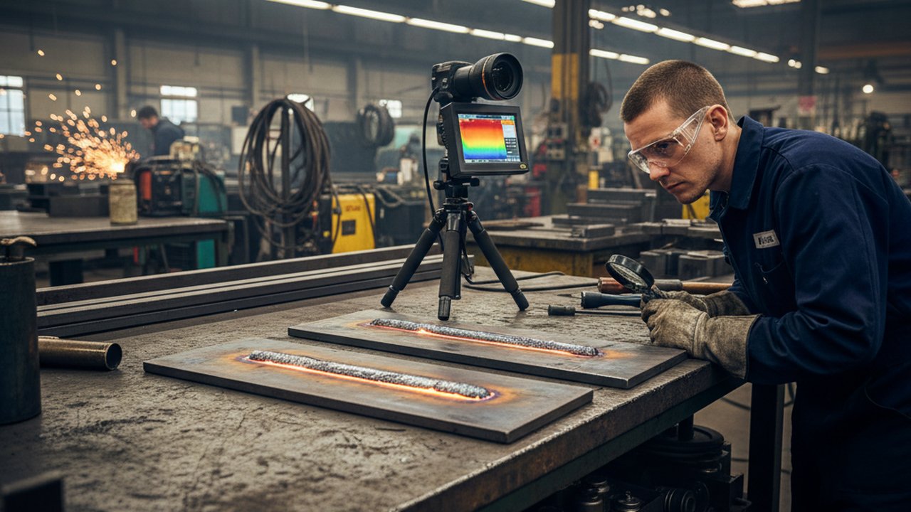
On the joint itself. Where fit-up gaps drive overwelding, a view of the joint before the arc beats a measurement after it: a welding camera makes gap, torch position and bead profile observable on cells nobody can stand beside, while the weld is still recoverable and before the gauge argument starts.
One-page verification checklist: convention stated on the drawing; leg and throat gauges calibrated; the worst point sampled rather than the tidiest; macro-section evidence for any credited penetration; parameter records kept for the shift; leg size confirmed inside the WPS range.
Joint choice sits upstream of all of it. If a connection would be better served by a groove weld than an ever-larger fillet, make that call with the weld joint design guide, and judge the result against the ISO 5817 quality levels guide.
Where to read the real numbers
- ISO 5817:2023, quality levels for imperfections in fusion-welded joints — the ISO acceptance framework for fillet profile and throat deficiency.
- ISO 2553:2019, symbolic representation of welded joints on drawings — the source of the
aandzconvention. - AWS D1.1/D1.1M:2025, Structural Welding Code — Steel — the American structural family, with its minimum fillet size clauses.
- ASME Boiler and Pressure Vessel Code — attachment weld rules for pressure equipment.
- The Eurocodes programme — the European design family carrying the throat-based resistance checks.
- CEN — check there for the current EN edition applicable in your country.
- Background reading: the TWI job knowledge library, the International Institute of Welding, the American Welding Society, the NDT education resource centre.
FAQ
Does a fillet weld size in millimetres refer to the leg or the throat? It depends on the drawing convention. ISO writes the design throat as a and the leg as z, and the letter before the number says which one is specified. Reading an a-dimension as a leg undersizes the joint.
Why is there no single fillet weld size chart in mm that works for every code? Each code derives its floor from a different mix of thickness, restraint and preheat rules, inside its own copyrighted tables. A chart lifted from one code and used under another can be non-conforming.
Where does the 0.707 factor in fillet weld sizing come from? It is the cosine of forty-five degrees. On an equal-leg fillet with a flat face, the shortest distance from theoretical root to weld face is the leg times that factor, 0.7071. It is geometry, not a code rule.
How do codes decide the minimum fillet weld size from plate thickness? The floor is a thermal argument, not a strength one. The thicker member pulls heat out fast, so a small bead cools quickly, hardens and can crack. The American structural codes index the minimum directly on the thicker part joined; the European family instead sets a flat minimum throat plus length rules rather than stepping the minimum by thickness.
What happens if a welder deposits a fillet larger than the drawing calls for? Oversize fillets burn consumables and arc time, add heat input and distortion, and can push the joint outside its qualified procedure range. On fatigue details a heavier weld often worsens the toe geometry.
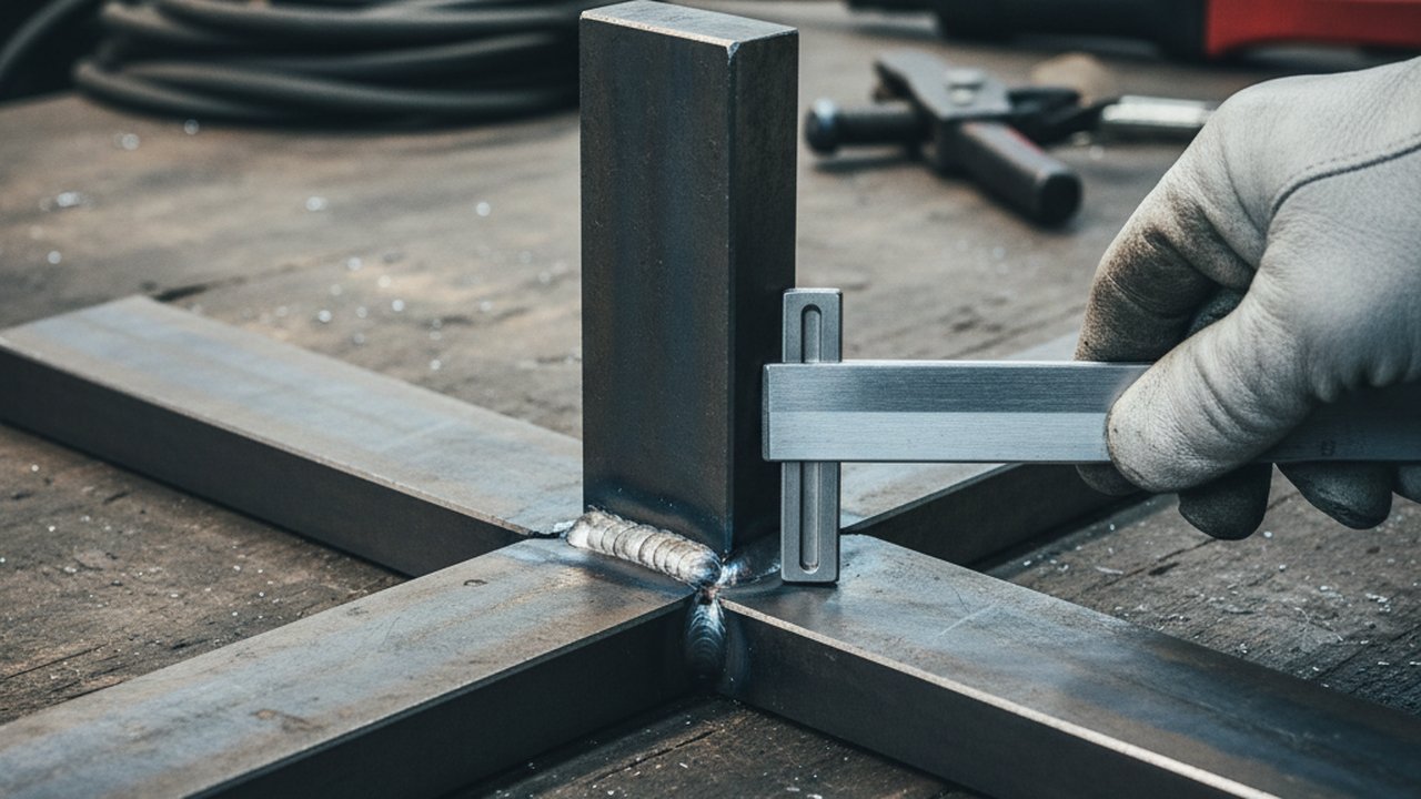
How is fillet weld size measured on the shop floor? With gauges: a leg gauge seated against both members, and a fillet gauge reading the effective throat on a concave profile. Macro-sections give the true throat. Measure the worst point, not the average.
Prove the fillet you specified is the fillet you welded
Continuous current, voltage, wire feed speed and travel records turn weld size from an after-the-fact measurement into a controlled production parameter.
Talk to us about parameter recordsTherness solution: Welding monitoring system — Every weld inspected in the cycle, with defect flags and the ISO 3834 / ISO 17635 evidence kept per weld.
Frequently Asked Questions
Does a fillet weld size in millimetres refer to the leg or the throat?
It depends on the drawing convention. ISO writes the design throat as a and the leg as z, and the letter before the number says which one is specified. Reading an a-dimension as a leg undersizes the joint.
Why is there no single fillet weld size chart in mm that works for every code?
Each code derives its floor from a different mix of thickness, restraint and preheat rules, inside its own copyrighted tables. A chart lifted from one code and used under another can be non-conforming.
Where does the 0.707 factor in fillet weld sizing come from?
It is the cosine of forty-five degrees. On an equal-leg fillet with a flat face, the shortest distance from theoretical root to weld face is the leg times that factor, 0.7071. It is geometry, not a code rule.
How do codes decide the minimum fillet weld size from plate thickness?
The floor is a thermal argument, not a strength one. The thicker member pulls heat out fast, so a small bead cools quickly, hardens and can crack. The American structural codes index the minimum directly on the thicker part joined; the European family instead sets a flat minimum throat plus length rules rather than stepping the minimum by thickness.
What happens if a welder deposits a fillet larger than the drawing calls for?
Oversize fillets burn consumables and arc time, add heat input and distortion, and can push the joint outside its qualified procedure range. On fatigue details a heavier weld often worsens the toe geometry.
How is fillet weld size measured on the shop floor?
With gauges: a leg gauge seated against both members, and a fillet gauge reading the effective throat on a concave profile. Macro-sections give the true throat. Measure the worst point, not the average.