Emissivity is the largest single error source when a thermal camera measures a steel or aluminium weld, and it is the one most often left at a default value nobody can justify. The camera is honest: it reports what its radiometric model implies from the signal it collected. If the emissivity in that model is wrong, the temperature is wrong by a margin that no amount of resolution, frame rate or software polish will recover.
This guide covers what emissivity does to a welding measurement, how carbon steel, stainless and aluminium differ, and the procedure that turns a setting into evidence.
Key takeaways
- Emissivity is not a material constant. It varies with wavelength, temperature, surface roughness, oxidation state and viewing angle.
- On low emissivity metal, most of what the camera collects is reflected surroundings, so the reflected background value matters as much as the emissivity value.
- Welding changes the surface while you measure it. An emissivity model established before the first pass is stale by the third.
- Aluminium is the hard case: low emissivity and high conductivity together mean small errors and slow readings both cost you the peak.
- A prepared reference spot on the part beats a clever number in the software, every time.
- The deliverable is not a setting. It is a pair of records — camera reading and calibrated contact reading — that agree repeatably on your own material.
What emissivity is, and what the camera does with it
Emissivity is the ratio between the radiation a real surface emits and the radiation a perfect emitter at the same temperature would emit, within the wavelength band the instrument accepts. A perfect emitter scores one; a mirror-like metal surface scores close to zero.
The three terms in every radiometric reading
What reaches the detector is the sum of three contributions: radiation emitted by the target, radiation from the surroundings that the target reflects toward the camera, and radiation from anything in the optical path between them. For an opaque metal, the first two dominate, and their split is set by emissivity — a surface with an emissivity of two tenths emits two tenths and reflects eight tenths of what is behind the camera.
That is the difficulty in one sentence. On a bright metal the camera is largely photographing the room, and the temperature it reports depends on what the room is doing. The procedure for determining and compensating for reflected apparent temperature, emissivity and attenuating media is set out in ISO 18434-1, the general-procedures part of the machine condition-monitoring thermography series, and is worth following as written.
Why metals are the hard case
Non-metals — paint, oxide, ceramic, refractory — radiate efficiently and are relatively insensitive to how they are viewed. Metals do the opposite: emissivity is low, depends strongly on wavelength, and changes as soon as the surface does. Because that dependence is spectral, a value right for one instrument is not automatically right for another, which is why the choice of infrared wavelength band and the emissivity model must be decided together. The welding camera hub covers where each instrument class sits before the emissivity question arises.
Steel and aluminium behave differently
Carbon and low alloy steel
Steel is the forgiving case, but only once it has oxidised. Bright ground or machined steel is a poor emitter; the same surface after heating carries an oxide layer that radiates far more efficiently. Mill scale behaves similarly.
The practical consequence is a moving target during welding. As passes accumulate, the surface darkens and its emissivity climbs, so an unchanged software setting makes the camera report a temperature rise that the metal did not experience. Multi-pass work therefore needs either a reference spot whose condition is controlled or a model that acknowledges the change; the workflow behind that is covered in the interpass temperature limits and control guide.
Stainless steel
Stainless is the most misleading of the three. A polished austenitic surface is a strong reflector and, in the long wave band, a weak emitter. Heat tint changes that dramatically and unevenly, so a single joint can carry several distinct emissivity zones within a few centimetres. Stainless also constrains the fix: crayons, tapes and paints containing halogens or sulphur are commonly restricted near austenitic and nickel-based materials, so a reference patch has to be a qualified consumable rather than whatever is on the bench.
Aluminium and its alloys
Aluminium combines the two worst properties for infrared work. Its natural oxide is thin and its bright surface radiates very poorly, so the reflected term dominates almost completely. At the same time its thermal conductivity is roughly three to five times that of carbon steel, and an order of magnitude more than austenitic stainless, so gradients flatten within seconds and a reading taken a moment late has already lost the value it was meant to capture. Anodised or heavily oxidised aluminium behaves much better, which is exactly why prepared reference marks are close to mandatory on aluminium fabrication. The material-specific workflow is set out in the guide to aluminium welding quality monitoring with thermal imaging.
On aluminium, the question is rarely “what emissivity should I enter”. It is “how do I create a spot on this part whose emissivity I actually know”. Answer that and the software setting becomes bookkeeping.
Decision table: choosing an emissivity strategy
| Situation | Workable strategy | Why it holds | Cost or limit |
|---|---|---|---|
| Oxidised carbon steel, arc off, interpass check | Software value plus periodic contact cross check | Oxide emissivity is high and reasonably stable | Drifts as scale thickens over many passes |
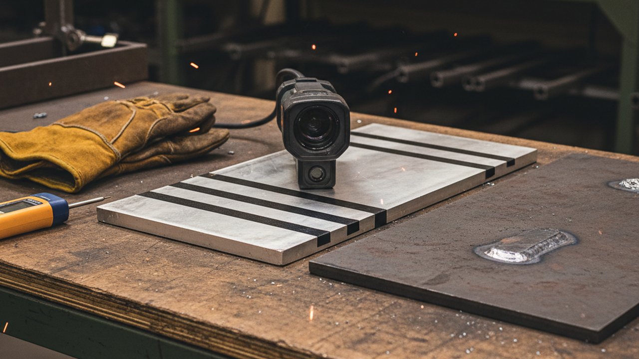
| Ground or machined steel before welding | Prepared reference patch adjacent to the joint | Removes the low emissivity surface from the measurement | Patch must survive handling and heat |
| Polished stainless with heat tint | Reference patch, qualified consumable only | Tint zones are non-uniform and unpredictable | Consumable restrictions on austenitic grades |
| Bright aluminium plate | Reference patch, mandatory | Reflected term otherwise dominates the signal | Patch placement must not contaminate the joint |
| Anodised or coated aluminium | Software value, verified once per batch | Coating emissivity is high and repeatable | Verify per coating supplier, not per alloy |
| Enclosed cell with hot fixtures | Measure reflected background before every campaign | Background is the dominant unknown, not emissivity | Needs a repeatable measurement position |
| Additive build, layer on layer | Reference on the substrate plus a per-layer trend | Absolute value is unstable; the trend still is not | Trend only detects change, not absolute breach |
Where the recorded temperature has to satisfy a qualified range, the measurement method is itself governed. ISO 13916 specifies requirements for measuring preheating, interpass and preheat maintenance temperatures, and a radiometric method has to meet those requirements, not substitute for them. The related workflow is covered in the preheat and interpass monitoring guide.
Failure modes and fixes
Every reading is low, and consistently so
Emissivity is set too high for the surface. The camera assumes the surface emits efficiently, receives less signal than that assumption predicts, and concludes the part is cooler. The tell is that the error scales with the difference between part and surroundings.
Readings climb through a multi-pass joint with no real heat gain
Oxidation, as above. Fix it with a prepared reference spot rather than by tuning the setting between passes, which merely moves the fiction around.
A shiny part reads hotter when someone stands beside the cell
Reflection. On a low emissivity surface, a warm body, a lamp, a hot fixture or an open furnace door all contribute. Determine the reflected apparent temperature properly and re-enter it whenever the cell layout changes.
Aluminium reads plausibly in the morning and badly after lunch
Surface state. Handling, fresh oxide, coolant residue and fingerprints all move emissivity on aluminium far more than they would on scaled steel. Prepared references and a defined cleaning step remove most of it.
Two operators get different numbers on the same joint
Usually viewing angle and spot size. Emissivity is not constant with angle, and a spot that overlaps the bead edge averages two different surfaces. Fix the geometry in the procedure — angle, distance, spot placement — rather than treating it as operator skill.
Numbers were fine until the protective window was replaced
Any window attenuates, and a replacement is rarely optically identical. Treat a window change as a re-verification trigger and record the part number of what was fitted.
Step by step: establishing an emissivity model
- Define the measurement point. A named, marked location — not “near the weld”. Everything else depends on this being repeatable.
- Record the production surface condition. As-rolled, ground, scaled, tinted, anodised, painted. Photograph it. This is what changes between qualification and production and is almost never written down.
- Determine the reflected apparent temperature at the measurement position, following the general thermography procedure, and record it alongside the emissivity value.
- Choose the strategy from the table above. Where a reference patch is used, confirm the consumable is acceptable for the material and stays clear of the fusion zone.
- Fix the geometry. Viewing angle close to normal, standoff distance stated, spot size small enough to sit entirely inside one surface condition.
- Set the value and run the paired trial described below before anything is recorded as evidence.
- Write the result into the inspection procedure, including the re-verification triggers, so the number has an owner rather than a history.
Emissivity checklist. Measurement point marked. Surface condition recorded and photographed. Reflected apparent temperature determined and logged. Strategy chosen and consumable approved. Viewing angle and standoff fixed. Spot size inside one surface condition. Paired trial completed at two temperatures. Re-verification triggers written into the procedure.
Verification: proving the number
An emissivity setting is verified when the camera and a calibrated reference agree, repeatably, on your material and surface condition, at more than one temperature.
The paired trial
Take a coupon in the production surface condition. Bring it to the low end of your working range, record the camera reading, then immediately take a calibrated contact reading at the marked spot. Repeat at the high end. Do at least five pairs at each level and keep all of them.
Read the pattern, not the average. A constant offset suggests the reflected background value. An offset that grows with temperature suggests emissivity. Scatter without a trend suggests geometry, spot size or timing. The practice of measuring and compensating emissivity with an imaging radiometer is described in ASTM E1933, which is the standard most laboratories work to for this specific step, and the terminology it shares with other documents is fixed by ISO 10878, the vocabulary standard for infrared thermographic testing.
Traceability and competence
The calibration chain behind the reference instrument ends at national metrology work such as the radiation thermometry programme at NIST, whose published measurement literature carries the uncertainty analysis. The thermography certification schemes run by ASNT and BINDT exist because emissivity handling is judgement. Applied case material surfaces first at NDT.net and in guidance from TWI.
What the record has to contain
The emissivity value and its justification, the reflected apparent temperature, the surface condition, the viewing angle and standoff, the instrument and window fitted, the reference instrument and its calibration status, and the raw pairs. That is the difference between a measurement and an opinion, and it is what a reviewer working to the qualification frameworks published by AWS or under the European system coordinated by CEN and CENELEC will look for.
Putting it into production
In a running cell the emissivity model belongs to the installation, not the operator: written into the recipe, carrying its re-verification triggers, versioned with the rest of the welding monitoring system configuration. HeatCam IR-C is the long wave instrument we fit for that role — cell-mounted, fixed geometry, one measurement point that stays where the procedure says it is. Fixed geometry removes two of the error sources above by construction.
Where the question underneath the temperature is really energy delivered rather than surface state, the heat input calculator handles the parameter side, and the field thermography inspection guide covers handheld work where geometry cannot be fixed and the discipline has to be stricter.
FAQ
Why does emissivity change during a weld rather than staying constant? Because the surface changes. Oxide grows, scale forms and spatter lands, and each of those raises the efficiency with which the surface radiates. A value measured on a clean coupon before welding no longer describes the same coupon after three passes, so the camera reports a rise that never happened.
Is it better to correct emissivity in software or to modify the surface? Modify the surface where the process allows it. A software value is an assumption applied uniformly to a scene that is not uniform, whereas a prepared high emissivity patch gives the camera a spot whose behaviour is known and repeatable. Software correction then handles the rest of the frame.
How does aluminium differ from steel for infrared temperature measurement? Aluminium radiates far less efficiently than oxidised steel, so a larger share of what the camera sees is reflected surroundings rather than the part. Conductivity is also much higher, so thermal gradients flatten quickly and a delayed reading loses the peak the measurement was meant to capture.
What is reflected apparent temperature and why does it matter on shiny metal? It is the effective temperature of everything radiating onto the target that the target then reflects toward the camera. On a low emissivity surface most of the signal is that reflection, so entering an ambient value when the real surroundings include a hot fixture produces a confidently wrong reading.
How do you prove an emissivity setting to an auditor? With paired records: the camera reading and a calibrated contact reading taken at the same marked spot, over several repeats and at least two temperatures, plus the emissivity value used, the reflected background value and the surface condition. The pairs are the evidence; the setting alone is only a claim.
Does high emissivity paint or tape belong on a production part? Sometimes, but it has to be qualified like any other consumable in contact with the joint. Materials that leave halogen or sulphur residues are restricted on stainless steels and nickel alloys, and anything applied inside the fusion zone risks contamination, so references usually sit adjacent to the weld.
Get the emissivity question settled before it costs you a record
Tell us the material, the surface condition and where the measurement has to be taken. We will say which strategy holds on your parts, and where a reference spot is unavoidable.
Review your measurement setupTherness solution: Welding camera — Thermal and high-speed imaging that watches the arc, the pool and the cooling seam while the weld is made.
Frequently Asked Questions
Why does emissivity change during a weld rather than staying constant?
Because the surface changes. Oxide grows, scale forms and spatter lands, and each of those raises the efficiency with which the surface radiates. A value measured on a clean coupon before welding no longer describes the same coupon after three passes, so the camera reports a rise that never happened.
Is it better to correct emissivity in software or to modify the surface?
Modify the surface where the process allows it. A software value is an assumption applied uniformly to a scene that is not uniform, whereas a prepared high emissivity patch gives the camera a spot whose behaviour is known and repeatable. Software correction then handles the rest of the frame.
How does aluminium differ from steel for infrared temperature measurement?
Aluminium radiates far less efficiently than oxidised steel, so a larger share of what the camera sees is reflected surroundings rather than the part. Conductivity is also much higher, so thermal gradients flatten quickly and a delayed reading loses the peak the measurement was meant to capture.
What is reflected apparent temperature and why does it matter on shiny metal?
It is the effective temperature of everything radiating onto the target that the target then reflects toward the camera. On a low emissivity surface most of the signal is that reflection, so entering an ambient value when the real surroundings include a hot fixture produces a confidently wrong reading.
How do you prove an emissivity setting to an auditor?
With paired records: the camera reading and a calibrated contact reading taken at the same marked spot, over several repeats and at least two temperatures, plus the emissivity value used, the reflected background value and the surface condition. The pairs are the evidence; the setting alone is only a claim.
Does high emissivity paint or tape belong on a production part?
Sometimes, but it has to be qualified like any other consumable in contact with the joint. Materials that leave halogen or sulphur residues are restricted on stainless steels and nickel alloys, and anything applied inside the fusion zone risks contamination, so references usually sit adjacent to the weld.