Weld joint design determines not just the mechanical performance of a connection, but whether a qualified welder can consistently produce the joint to the required quality level under normal production conditions. Select the wrong joint type or specify a groove geometry that defies practical execution, and you will be managing welding defects and NCRs instead of shipping product. Yet across fabrication shops and engineering offices, joint design decisions default to “what we did on the last job” rather than a systematic match of load path, process capability and code requirements.
This guide covers the five fundamental joint types, the sizing rules that govern fillet and groove welds, the international codes that mandate specific geometries, a decision framework connecting joint choice to ISO 5817 acceptance criteria, and the most common failure modes you will encounter when design and execution diverge.
Weld joint design at a glance
Weld joint design is five decisions taken before the first arc: joint type, weld type, weld size, penetration class and groove preparation, each checked against the code the contract names. The short answers, with clause numbers from AWS D1.1/D1.1M:2025, the current edition of the structural steel code:
- Joint types: butt, T, corner, lap and edge. The joint type is the position of the parts; the weld type (fillet, groove, plug or slot) is what fills it.
- Fillet weld size: drawings give the leg z or, in ISO practice, often the throat a; calculations always use the effective throat a; for an equal-leg fillet, a = 0.707 × z. Minimum fillet sizes, stepped by base-metal thickness, are in Table 7.7 (subclause 7.13); the maximum along a plate edge is in Figure 4.7.
- FJP/CJP or PJP: complete joint penetration (CJP in AWS terms) fuses the whole thickness and is the default for tension, bending and fatigue. Partial joint penetration is designed on a declared effective throat smaller than the plate.
- Groove preparation: groove angle, root opening and root face are set together. The prequalified ones are drawn in Figure 5.1 (CJP) and Figure 5.2 (PJP), fillet details in Figure 5.3; ISO 9692-1:2013 gives recommended preparations for steels. Outside a prequalified detail the WPS is qualified by test (Clause 6).
- Acceptance criteria: visual acceptance under AWS D1.1 is Table 8.1; on ISO work it is the ISO 5817:2023 quality level, B, C or D, named on the drawing. Joint design decides how hard that level is to reach.
Key Takeaways
- Weld joint design governs load transfer efficiency, weld quality achievability and code compliance simultaneously — it is not a detail to delegate to habit or copy-paste.
- Fillet weld effective throat = 0.707 × leg size; this is the governing dimension for all structural calculations, not the visible leg dimension on the drawing.
- Minimum fillet weld sizes (AWS D1.1/D1.1M:2025 Table 7.7) keep a small bead on thick steel from cooling too fast; they are not strength specifications, and the required structural size is often larger.
- Full joint penetration (FJP) is the default for primary tension, bending and fatigue-critical members; partial penetration (PJP) is designed on its declared throat and needs a fatigue check where loads cycle.
- Groove angle, root opening and root face are set together for each process and position; wrong values produce incomplete root penetration, which ISO 5817 limits by quality level.
- Prequalified joint details per AWS D1.1/D1.1M:2025 Clause 5 (Figures 5.1–5.3), used within their tolerances, remove the need for procedure qualification testing.
- The correct joint design makes ISO 5817 Quality Level B reachable with normal workmanship; the wrong design makes it very hard to reach, whatever the welder skill.
Table of Contents
- The Five Basic Weld Joint Types
- Fillet Weld Sizing: Throat, Leg and Shear Capacity
- Butt Weld Design: Full vs Partial Penetration
- Joint Selection Decision Framework
- Groove Preparation: AWS D1.1 and ISO 9692 Requirements
- Common Failure Modes and Fixes
- ISO 5817 Acceptance Criteria by Joint Type
- FAQ
The Five Basic Weld Joint Types
Every welded connection belongs to one of five geometric categories, defined by the relative position of the members being joined. The joint type determines which weld type applies, which groove geometry is required, and which code rules govern sizing and inspection.
Butt joint — Two plates aligned in the same plane, joined edge to edge. The weld fills a groove prepared between the edges. Butt joints with full penetration achieve 100% joint efficiency, making them the usual choice for primary pressure-containing seams in piping systems, process vessels and structural primary tension members. AWS D1.1/D1.1M:2025 and ASME Section IX both qualify groove-weld procedures on butt test joints.
T-joint — One member meets the surface of another at approximately 90°. Typically welded with double fillet welds on both sides for shear connections, or with a single-bevel groove providing partial or full penetration where bending or fatigue loads govern. T-joints are the most common joint type in structural steel frames, crane girder webs, machine bases and pressure vessel nozzle attachments.
Corner joint — Two members forming an L-shape, meeting at their edges. Can be executed as an outside fillet weld, a square butt groove or a full-penetration V-groove depending on the load and access conditions. The open-corner configuration (exposed root, no backing) is the simplest to fit-up but develops a stress concentration at the unwelded root under bending — unsuitable for fatigue-loaded enclosures or frames.
Lap joint — Two overlapping plates joined by fillet welds along one or both exposed edges. Structurally inefficient in tension due to the eccentric load path and weld-toe stress concentration, but useful in shear applications, thin sheet work and non-critical connections where fit-up simplicity is more valuable than structural optimisation. Eurocode 3 EN 1993-1-9 assigns lap joints to lower fatigue detail categories than butt welds — a deliberate code recognition of their inherent stress-concentration geometry.
Edge joint — Two parallel plates joined at their edges, primarily used to seal or tack thin-gauge sheet panels. Rarely used for load-carrying connections.
Weld joint type and weld type appear on engineering drawings using welding symbols per AWS A2.4 (US practice) or ISO 2553 (international practice). Confirm with your customer which notation system governs before issuing fabrication drawings — mixing conventions is a consistent source of misread joint preparations on the shop floor.
Fillet Weld Sizing: Throat, Leg and Shear Capacity
The effective throat a is the structural governing dimension of a fillet weld — not the leg size z that appears on fabrication drawings. For a standard equal-leg fillet weld deposited at the theoretical geometry (45° bisector):
a = 0.707 × z
A 10 mm fillet weld (leg) produces an effective throat of 7.07 mm. This is the dimension through which shear force is resolved in structural calculations. Working back from a required load:
Required leg z = F / (0.707 × f_w × L)
where F is the applied force (N), f_w is the design shear strength of the weld metal (N/mm²), and L is the weld length (mm). AWS D1.1/D1.1M:2025 derives the weld strength from the electrode classification strength F_EXX (Table 4.3, available strength of welded joints) and credits load direction for fillets (Table 4.4); Eurocode 3 EN 1993-1-8 applies a correlation factor β_w tied to the base metal ultimate strength. Always verify which code governs before sizing.
Minimum fillet weld sizes are not strength requirements. They exist because a small bead deposited on a thick section cools too fast, which hardens the heat-affected zone and invites cracking. AWS D1.1/D1.1M:2025 sets them in Table 7.7 (subclause 7.13), stepped by base-metal thickness; read the values from the edition your contract names, because earlier editions carried the rule under other table numbers. A fillet weld size chart in mm explains how the American and European rules differ.
Always calculate required throat from load first, then verify the result meets both the strength requirement and the minimum-size floor. The larger value governs the drawing callout.
Maximum fillet weld size along a plate edge is limited so the weld does not melt away the edge and hide the true leg: AWS D1.1/D1.1M:2025 shows the rule in Figure 4.7 (Maximum Specified Fillet Weld Size Along Edges), new in the 2025 edition.
A drawing may give the fillet size as the leg z or, in ISO practice, often as the throat a (for example “a5”); check which letter precedes the size. Every structural calculation uses the throat a. Keep both on your calculation sheet and confirm the callout matches the calculated value for the letter it uses.
Butt Weld Design: Full vs Partial Penetration
The penetration class is a design decision — one that has direct consequences for joint efficiency, fatigue performance and inspection requirements.
Full joint penetration (FJP / CJP — complete joint penetration) extends through the entire thickness of the thinner member, achieving 100% joint efficiency in tension. Designers specify FJP for:
- Primary tension and moment connections in structural steel frames under AWS D1.1
- Circumferential butt welds in ASME B31.3 process piping, where Table 341.3.2-1 limits incomplete penetration by fluid service category
- Main seams of pressure vessels, where the joint efficiency used in the design depends on the joint type and the extent of radiography
- Cyclically loaded details, where an unfused root acts as a crack starter
FJP requires groove preparation (see Groove Preparation below) and a backing bar or back-gouging to confirm root fusion; contracts usually call for volumetric NDE (UT or RT) to verify root integrity. A CJP joint welded from one side without backing is outside the AWS D1.1 prequalified details and needs a WPS qualified by test (Clause 6).
Partial joint penetration (PJP) uses a calculated effective throat smaller than the member thickness. PJP is appropriate for:
- Joints carrying only compressive loads, where full efficiency is unnecessary by design
- Connections designed with a reduced joint efficiency or a declared effective throat
- Cases where access prevents back-gouging and a backing bar is undesirable or impractical
PJP joints carry a fatigue penalty. The unfused root is an inherent notch that amplifies cyclic stress at the root tip. Eurocode 3 EN 1993-1-9 puts PJP welds in lower fatigue detail categories than equivalent FJP joints — a code-recognised acknowledgement of the root notch effect. Do not use PJP in any fatigue-critical application without an explicit fatigue life calculation confirming adequacy.
Design rule: if in doubt between FJP and PJP, choose FJP for any joint that will see cyclic loading, external bending, or repeated thermal cycling. The additional inspection cost is real; the failure cost of an undersized root in service is larger.
Joint Selection Decision Framework
This matrix condenses the code-driven selection logic into a working shop-floor reference:
| Load type | Access | Preferred joint | Penetration class |
|---|---|---|---|
| Primary tension or bending | Both sides | Double-V butt | FJP |
| Primary tension or bending | One side only | Single-V butt + backing bar | FJP |
| Fatigue (any load direction) | Both sides | Double-V butt or T-joint groove | FJP |
| Shear (secondary) | Both sides | Double fillet T-joint | Fillet |
| Shear (secondary) | One side | Single fillet T-joint | Fillet |
| Compressive only | Either | Corner fillet or PJP groove | Fillet or PJP |
| Seal / thin sheet | Either | Lap or edge fillet | Fillet |
| Attachment weld (no structural load) | Either | Fillet or plug/slot | Fillet |
Cross-reference the selected joint against the applicable code to confirm the configuration is permitted for the application and execution class. A weld map that records the joint type, applicable code clause and required ISO 5817 quality level for each weld ID is the audit document that links design intent to production records — the traceability that ISO 3834-2 and EN 1090-2 work relies on when the contract asks for it.
Groove Preparation: AWS D1.1 and ISO 9692 Requirements
Groove geometry controls root fusion, which is the leading mechanical cause of incomplete penetration defects. Three interdependent parameters govern every groove specification:
Groove angle — The total included angle between the two groove faces. In AWS D1.1/D1.1M:2025 every prequalified CJP detail in Figure 5.1 states its own angle, root opening and root face, with tolerances, for a given process, position and backing; the 2025 edition replaced those drawings, so take the values from the current figure. ISO 9692-1:2013 gives recommended joint preparations for steels by thickness and process. A narrow angle reduces sidewall access for electrode manipulation and raises the probability of lack of fusion at the bevel faces. A wide angle increases angular distortion and needs more filler metal and heat input per unit joint length.
Root gap (root opening) — The opening between workpiece edges at the root before welding begins. The prequalified detail or the WPS states it in millimetres with a tolerance, and AWS D1.1/D1.1M:2025 subclause 7.21 sets the tolerance of joint dimensions at fit-up. A closed root depends on back-gouging from the second side; an open root welded from one side needs either a backing or a root pass that fuses both edges, which demands precise fit-up across the full joint length.
Root face (land) — The flat, unbevelled edge portion at the root, a few millimetres at most. A root face prevents burn-through by providing a thermal bridge at the root during the first pass. It must be removed by back-gouging if back-side access is available and full-penetration is required on both sides, or fully consumed by a hot root pass if a ceramic backing strip is used.
All three parameters are written into the WPS. Under ISO 15614-1 the procedure is qualified on a test joint, and a change beyond its range of qualification needs a new qualification. Prequalified joint details per AWS D1.1/D1.1M:2025 Clause 5 (Figures 5.1–5.3), used within their tolerances, bypass procedure testing entirely, which is one of the most practical arguments for specifying AWS prequalified joint configurations wherever the project code permits.
Never weld a groove joint that deviates from the WPS-specified groove dimensions without re-qualifying the procedure or switching to an approved prequalified joint. Incomplete root penetration is one of the imperfections ISO 5817 limits by quality level, and on a full-penetration joint it also breaks the design assumption: read its row for the level the drawing names before accepting any.
Common Failure Modes and Fixes
Most weld joint design failures fall into a small set of recurring patterns. Each has a deterministic root cause and a specific fix:
| Failure mode | Root cause | Fix |
|---|---|---|
| Incomplete root penetration | Root gap ≤ 0 mm, excessive land, heat input below WPS range | Bring root opening and land back to the WPS or prequalified detail; verify heat input per welding heat input calculation |
| Lack of sidewall fusion | Groove angle too narrow, incorrect electrode angle, excessively fast travel | Open the groove to the WPS angle; correct torch angle to address sidewall; add slight weave on SMAW root pass |
| Angular distortion in butt joints | Single-sided weld with no restraint; imbalanced heat input | Specify double-V (welded both sides); apply pre-set counter-camber; use balanced welding sequence (alternate sides) |
| Undersized fillet weld | Drawing callout copied from previous job without structural calculation | Recalculate required leg from load + electrode F_EXX; update drawing callout; verify with calibrated weld gauge during visual inspection |
| Lamellar tearing (T-joints in rolled plate) | Through-thickness tensile strain during cooling; elevated sulfur in base metal | Specify Z-grade (Z25/Z35) steel per EN 10164; redesign to spread load over FJP groove; apply preheat to slow cooling rate |
| Crater cracking at weld stop | Abrupt arc termination without crater fill | Use run-off tabs at joint ends; use crater fill technique or back-step at stop end; verify with visual inspection |
| Cold lap / overlap at weld cap | Excessive current for cap pass; travel speed too slow | Increase travel speed; reduce amperage to WPS range; verify interpass temperature before cap |
Real-time weld monitoring during production can detect arc interruptions, torch-angle deviations and travel-speed excursions — the upstream signals for incomplete fusion and insufficient throat — before they produce ISO 5817 non-conformances requiring costly repair or cut-out. A weld monitoring system also generates the production data records that confirm WPS compliance across the full joint length. The Therness product range supplies the cameras and analytics behind this, as shown in the system overview.
ISO 5817 Acceptance Criteria by Joint Type
ISO 5817:2023 defines acceptance criteria for fusion-welded joints at Quality Levels B (highest stringency), C and D. Joint design affects which imperfections are probable and whether achieving Level B demands extraordinary effort or normal production practice.
| Joint type | Typical ISO 5817 imperfection risk | What decides acceptance |
|---|---|---|
| Single-V butt FJP | Incomplete root penetration | Its row in ISO 5817 for the level named; on a full-penetration design it also breaks the strength assumption |
| Single-V butt FJP | Root concavity | Depth limit for the level, read against the wall thickness |
| Double fillet T-joint | Undercut | Depth limit for the level, which depends on the plate thickness |
| Double fillet T-joint | Insufficient throat thickness | The design throat, checked along the full weld length |
| Lap fillet | Overlap (cold lap) | Its row for the level; it hides lack of fusion at the toe |
| Lap fillet | Angular misalignment | Tolerance for the level and the fit-up of the assembly |
| PJP groove | Unfused root (by design) | Not a defect: the declared effective throat is what gets verified |
| Corner (open root) | Root concavity, burn-through | Their rows for the level; access to the root decides both |
The key insight from this table is that joint design sets the baseline probability for each imperfection type. A single-V butt joint prepared to the angle, root opening and land of its WPS or prequalified detail gives a competent qualified welder the geometric conditions to achieve Level B without rework. The same joint with a much narrower groove and a closed root gap makes Level B very hard to reach whatever the welder skill, because the geometry denies access to the root.
This is why joint design review belongs in the quality plan before the first arc is struck — not in the non-conformance report after the first RT sequence.
Connecting joint type and required quality level in the weld map and linking it to the welder’s active qualification via the welder continuity record creates the audit-ready traceability trail that ISO 3834-2 fabrication and EN 1090-2 execution classes call for.
FAQ
What is the difference between a fillet weld and a butt weld? A fillet weld joins two surfaces at approximately right angles (T-joint, corner, lap) using a triangular cross-section deposited without groove preparation. A butt weld joins two pieces edge-to-edge in the same plane, requiring groove preparation. Butt welds achieve higher joint efficiency in tension; fillet welds require no groove machining and tolerate more fit-up variation.
How do you calculate fillet weld throat thickness? For an equal-leg fillet weld, effective throat a = 0.707 × leg z. A 10 mm leg gives a 7.07 mm throat. This is the value used in shear and bending calculations under AWS D1.1 and EN 1993-1-8; ISO 2553 notation calls them a and z.
What is the minimum fillet weld size per AWS D1.1? AWS D1.1/D1.1M:2025 sets it in Table 7.7 (subclause 7.13), stepped by base-metal thickness; read the values from the edition your contract names. The minimum keeps a small bead on thick steel from cooling too fast; the size the load requires may be larger.
When should I use FJP versus PJP? Use FJP for primary tension, bending and fatigue-critical joints requiring 100% joint efficiency. Use PJP for compressive-only or explicitly reduced-efficiency joints. When in doubt, use FJP.
What groove angle is required for a butt weld? No single value: each prequalified CJP detail in AWS D1.1/D1.1M:2025 Figure 5.1 fixes its own angle, root opening and root face by process, position and backing, and ISO 9692-1:2013 gives recommended preparations for steels by thickness and process. Too narrow risks lack of root and sidewall fusion; too wide adds filler metal, heat and distortion.
How does joint design affect ISO 5817 quality level? Joint geometry sets the conditions that determine which imperfections can occur and at what probability. Correct groove geometry makes Level B reachable under normal production; geometry that denies access to the root makes it very hard to reach, whatever the welder skill.
What is the effective weld throat and why does it matter? Effective throat is the shortest distance from joint root to weld face and is the governing dimension in structural calculations. For equal-leg fillet welds it is 0.707 × leg. Undersizing the throat reduces load capacity without a visible change in weld size.
Can a fillet weld carry tensile loading? Yes. AWS D1.1/D1.1M:2025 credits load direction with equivalent strength coefficients for obliquely loaded fillet welds (Table 4.4), so a transversely loaded fillet is credited with more strength per unit length than a longitudinal one; take the coefficient from the table. In fatigue-critical applications, however, the weld-toe stress concentration at T-joints often makes FJP groove welds the safer design.
What is a plug weld or slot weld? A plug weld fills a circular hole drilled through one plate and fused to the surface below. A slot weld uses an elongated opening. Both are used where lap edge fillet welds cannot access the full joint perimeter. AWS D1.1/D1.1M:2025 covers them in subclauses 4.11 (design) and 7.24 (technique); for cyclically loaded structures, check 4.19 (Prohibited Joints and Welds) first.
Do prequalified joints eliminate WPS qualification testing? Yes, for joint details and WPS conditions that meet AWS D1.1/D1.1M:2025 Clause 5 exactly (Figures 5.1–5.3, within tolerances). Any deviation outside them requires a WPS qualified by testing under Clause 6 of AWS D1.1 or under ISO 15614-1.
Catch joint design execution issues before they become NCRs
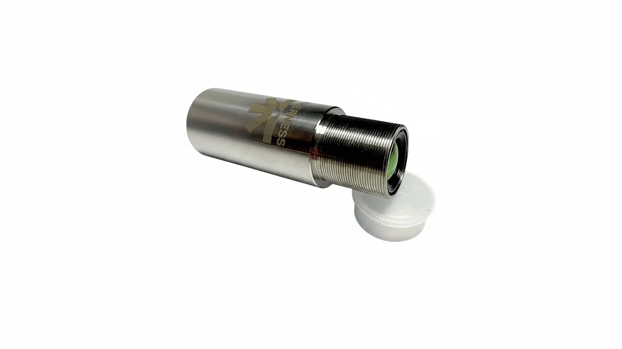
Therness weld monitoring systems detect arc anomalies, torch-angle deviations and heat input excursions during production — before joint design deficiencies translate into ISO 5817 non-conformances. For continuous thermal monitoring on the shop floor, the HeatCam IR-C is a cylindrical thermal camera for fixed production-line installs — see how it compares to arc-visualization weld cameras.
Request a DemoTherness solution: Welding monitoring system — Every weld inspected in the cycle, with defect flags and the ISO 3834 / ISO 17635 evidence kept per weld.
Frequently Asked Questions
What is the difference between a fillet weld and a butt weld?
A fillet weld joins two surfaces approximately at right angles (T-joint, corner, lap) using a triangular cross-section deposited without groove preparation. A butt weld joins two pieces edge-to-edge in the same plane, requiring groove preparation. Full-penetration butt welds carry tensile and bending loads at 100% joint efficiency; fillet welds are simpler to execute and tolerate more fit-up variation.
How do you calculate fillet weld throat thickness?
For a standard equal-leg fillet weld the effective throat equals 0.707 × leg size. A 10 mm leg fillet weld has an effective throat of 7.07 mm. This throat dimension — not the leg — is used in shear and bending calculations under AWS D1.1 and EN 1993-1-8. In ISO welding-symbol notation (ISO 2553) the throat is "a" and the leg is "z".
What is the minimum fillet weld size per AWS D1.1?
AWS D1.1/D1.1M:2025 sets it in Table 7.7 (subclause 7.13, Minimum Fillet Weld Sizes): the minimum leg steps up with base-metal thickness. Earlier editions carried the rule under other table numbers, so cite the table of the edition your contract names and read the values from it. The minimum keeps a small bead on a thick section from cooling too fast; it is not a strength check, and the size the load requires may be larger.
When should I use full joint penetration (FJP) versus partial joint penetration (PJP)?
Use FJP (complete joint penetration) for primary tension, bending and fatigue-critical members where 100% joint efficiency is required by code or design. Use PJP when loads are compressive, the joint efficiency is deliberately reduced in design calculations, or access prevents back-gouging. FJP needs a backing bar or back-gouging to sound metal, and contracts usually call for more volumetric NDE on it.
What groove angle is required for a butt weld?
There is no single value. In AWS D1.1/D1.1M:2025 each prequalified CJP detail in Figure 5.1 fixes its own groove angle, root opening and root face, with tolerances, by process, position and backing; the 2025 edition redrew those details. ISO 9692-1:2013 gives recommended preparations for steels by thickness and welding process. A narrow angle limits access to the sidewalls and the root; a wide one adds filler metal, heat input and angular distortion.
How does joint design affect ISO 5817 acceptance quality level?
Joint design sets the geometric conditions that decide which ISO 5817:2023 imperfections are likely. A root opening that is too tight or a root face that is too thick leads to incomplete root penetration, one of the imperfections ISO 5817 limits by quality level; the drawing or contract names the level, B, C or D. Correct groove geometry makes level B reachable with normal workmanship. Geometry that denies access to the root makes it very hard to reach, whatever the welder skill.
What is the effective weld throat and why does it matter?
The effective throat is the shortest distance from the joint root to the weld face — the governing dimension for structural calculations. For equal-leg fillet welds it is 0.707 × leg size. Undersizing the throat reduces load capacity without any change in the visible weld size, making it a common hidden error in fillet weld design.
Can a fillet weld carry tensile loading?
Yes. AWS D1.1/D1.1M:2025 credits the load direction: Table 4.4 gives equivalent strength coefficients for obliquely loaded fillet welds, so a transversely loaded fillet (load perpendicular to the weld axis) is credited with more strength per unit length than a longitudinally loaded one. Take the coefficient from that table, not from a rule of thumb. In fatigue-critical applications, however, the weld-toe stress concentration at T-joints often makes a full-penetration groove weld the safer design choice.
What is a plug weld or slot weld?
A plug weld fills a circular hole drilled through one plate and fused to the surface below. A slot weld uses an elongated opening instead. Both are used where lap edge fillet welds cannot access the full joint perimeter. AWS D1.1/D1.1M:2025 covers their design in subclause 4.11 and their technique in 7.24; for cyclically loaded structures, check subclause 4.19 (Prohibited Joints and Welds) before using them in members under tension.
Do prequalified joints eliminate WPS qualification testing?
Yes, when the joint and the WPS meet AWS D1.1/D1.1M:2025 Clause 5 (Prequalification of WPSs) exactly: a CJP, PJP or fillet detail from Figures 5.1, 5.2 or 5.3, used within its tolerances, with the base metals, processes and filler metals Clause 5 allows. A prequalified WPS needs no procedure qualification record (PQR). Any deviation outside those details or conditions requires a WPS qualified by testing under Clause 6, or under ISO 15614-1 on ISO work.