Foundry casting temperature thermography is usually sold as a way to measure molten metal, which is the one job it does worst. The value is elsewhere: on the ladle shell, the pouring stream, the mould face and the casting as it cools, thermography sees whole surfaces continuously, on every heat, in places where a foundry has historically had one sampled number and a lot of experience.
That distinction decides whether an installation pays back. A camera aimed at a bath of liquid metal in the hope of replacing an immersion thermocouple will produce numbers that drift with the slag film and disagree with the laboratory. The same camera aimed at the mould face between shots will find heat extraction problems that nobody could see before. This article covers which temperatures are worth imaging, how to build the installation, how to verify it, and the failure modes that make a reading confidently wrong.
Key takeaways
- Thermography is strongest on solid oxidised surfaces and weakest on clean liquid metal, where emissivity is low, variable and masked by slag.
- Four surfaces repay continuous imaging: ladle and launder refractory shells, the pouring stream and cup, the mould or die face, and the casting through cooling and knockout.
- Emissivity, reflected background and the plume between lens and target must all be handled before a radiometric number means anything.
- A general-purpose industrial camera covers aluminium, most copper alloys and every refractory shell; the free surface of molten ferrous metal sits above its range and needs a dedicated instrument.
- Most installation failures are contamination, geometry drift and reflections, and each has a recognisable signature that separates it from a real process change.
- The record only becomes useful when it is stamped with heat number and mould identifier, so that a defect investigation becomes an analysis instead of an argument.
The four temperatures worth imaging
Ladle and launder shells
Refractory wear is a safety and cost problem that announces itself thermally long before it becomes visible. A hot spot on a ladle shell means the lining behind it has thinned, and a fixed camera watching ladles as they pass a station builds a wear history per vessel rather than a spot check per inspection. This is the single most established industrial use of thermography in metal casting, and the easiest to justify: the target is a solid oxidised steel shell, which is close to an ideal thermographic subject.
The pouring stream and cup
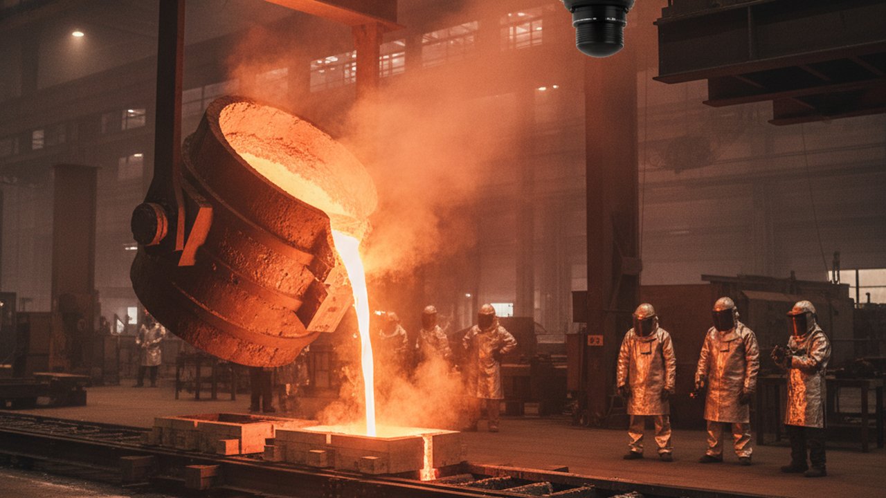
Pouring temperature drives fluidity, shrinkage behaviour and the tendency to misrun. A camera watching the stream and the cup gives a per-mould record of the pour, including fill sequence and the length of the pouring window, without any operator action. The stream is harder than the shell — it is narrow, moving and surrounded by fume — but it is imaged as a relative measurement across heats rather than as an absolute laboratory value.
The mould or die face
For permanent mould, die casting and any tooling that is reused, the face temperature between shots is the process variable. Coating condition, spray coverage and cooling channel performance all show as spatial patterns that repeat in the same geometry from cycle to cycle. The discipline here is identical to that of a fixed welding camera installation: a stable viewpoint, a defined region of interest and a trigger tied to the machine cycle.
The casting through cooling and knockout
Knockout temperature and cooling uniformity govern residual stress, distortion and, for some alloys, final microstructure. Imaging castings on the cooling line turns a scheduled dwell into a measured condition, and it catches the mould that came out early. The same logic drives thermal monitoring of post-weld heat treatment, where the controlled variable is also a cooling path rather than a peak.
Why a thermal image beats a spot reading
A radiometric camera converts the infrared radiance reaching its detector into temperature using an assumed emissivity, an assumed reflected apparent temperature and an assumed path transmission. Every one of those assumptions is under attack in a foundry. ISO 18434-1, the general procedures standard for thermography, is explicit about determining and compensating for emissivity, reflected apparent temperature and attenuating media, and a foundry installation that skips any of the three will produce plausible pictures containing wrong numbers.
Emissivity of metal, oxide and slag
Clean liquid metal is a poor emitter and a strong reflector. Oxidised solid steel is a good emitter. Slag, dross and mould coating each sit somewhere else again, and on a real pouring line all of them are present in the same frame within a few seconds of each other. This is the physical reason a camera is a poor bath thermometer and an excellent tool for solid surfaces: the surfaces that stay in one condition give repeatable readings, and the surfaces that change condition do not.
Reflected radiation in a hot bay
A foundry bay contains furnaces, hot moulds and glowing castings. All of them radiate onto whatever the camera is aimed at, and the background is not constant: it changes when a furnace door opens or a hot mould passes. Measuring the reflected apparent temperature in the real running condition, and repeating that when the layout changes, is what stops a background swing being read as a process event.
The plume between lens and target
Fume from the pour, steam from cooling water and dust from the sand system all absorb infrared. The consequence is an under-reading that appears exactly at the moment of interest. The fix is geometric — put the line of sight off the plume axis — plus a clean dry air purge across the window.
The most common false conclusion in foundry thermography is that a dip during pouring is a cold pour. Check the plume first. An attenuated path and a genuinely cold stream look identical in a single frame and separate immediately in a trend.
Choosing and siting the equipment
Instrument choice follows the measurement point, not the brochure. ISO 18251-1, which sets out the characteristics of infrared thermography systems and equipment, exists precisely to help a user match a system to a task across lens, detector, image processor and accessories.
| Measurement point | Instrument that fits | Why it fits | What it cannot do |
|---|---|---|---|
| Ladle and launder shell | Fixed radiometric camera | Whole-surface wear pattern, vessel by vessel | Cannot measure lining thickness directly |
| Bath temperature in the furnace | Immersion thermocouple | Direct contact with the melt, the accepted reference | No continuous coverage between samples |
| Pouring stream and cup | Fixed camera, triggered on pour | Relative per-mould record, no operator action | Not a laboratory-grade absolute value |
| Mould or die face between shots | Fixed camera on the machine cycle | Coverage and cooling appear as spatial patterns | Cannot see inside cooling channels |
| Casting on the cooling line | Fixed camera or scheduled survey | Cooling uniformity and knockout readiness | Cannot resolve internal gradients |
| Free surface of molten ferrous metal | Dedicated high-temperature instrument | Above the range of a general-purpose camera | Not covered by a standard industrial camera |
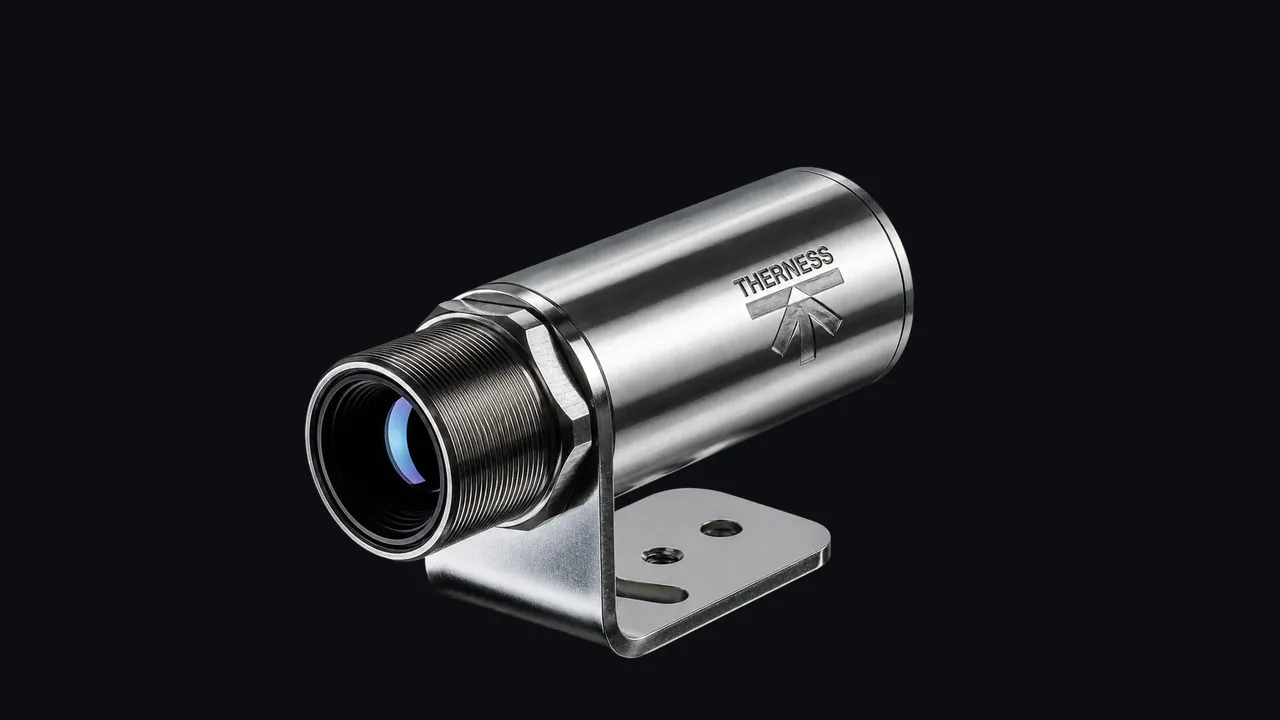
For everything above the last row, one device usually covers the plant. HeatCam IR-C, a cylindrical thermal camera built for fixed industrial installs, carries a 384 × 240 radiometric sensor over -20 °C to 900 °C (1500 °C with the optional range) with 60 mK sensitivity, Power over Ethernet and Modbus for a single-cable connection into the plant network, remote motorised focus, a choice of lenses and a high distance-to-spot ratio so the camera can sit far enough back to stay out of splash and fume. The same stream can be taken by software such as HeatCore Basic for alarms, statistics and a durable record.
Step-by-step implementation
Step 1 — Name the decision first
Decide what the data will change: ladle relining intervals, misrun scrap, knockout scheduling, or die spray maintenance. Each choice puts the camera in a different place. An installation without a named decision generates storage costs and nothing else.
Step 2 — Pick a target that stays in one condition
Prefer a surface whose emissivity does not change shot to shot: a shell, a coated mould face, a stripped casting. Where the target must be a stream or a bath, define the measurement as a comparison across heats rather than an absolute value, and say so in the procedure.
Step 3 — Site for the plume and the splash
Choose an angle close to normal on the target, off the axis of the fume plume, and outside the splash envelope. Mount on fixed structure rather than on moving equipment; a mount that moves destroys the comparability of every trend built on it.
Step 4 — Set emissivity and background in the running state
With the line running normally, take a contact reference on the target, adjust emissivity until the radiometric reading agrees, and measure the reflected apparent temperature from the surroundings as they actually are. Record both values with the date, the coating in use and the vessel or mould identifier.
Step 5 — Trigger on the process, not on a clock
Tie acquisition to the pour signal, the machine cycle or the passage of a vessel past the station. Free-running acquisition samples random moments and mixes hot and cold phases into a single meaningless average.
Step 6 — Baseline before alarming
Collect enough heats to characterise normal variation, then set warning and action levels from that record. Levels invented before the baseline exists are ignored within a week, or they stop the line for nothing.
Step 7 — Stamp the record with production identity
Every record carries heat number, mould or die identifier, alloy and shift. This is what turns a monitoring system into evidence, and it is the same argument as the one made for reducing scrap and rework by measuring inline.
Failure modes and fixes
| Symptom in the data | Likely cause | Fix |
|---|---|---|
| Steady downward drift over a shift, recovering after cleaning | Window contamination by fume, dust or spray | Restore the air purge, add window cleaning to the shift routine |
| Deep dip exactly during the pour | Fume plume crossing the line of sight | Move the viewpoint off the plume axis, compare against the trend before concluding |
| Step change after maintenance, no process change | Camera moved or refocused, regions of interest shifted | Re-establish geometry from the reference image, re-verify with a contact reading |
| Readings rise when a furnace door opens | Reflected background not compensated | Re-measure the reflected apparent temperature, shield the line of sight |
| Ladle readings scatter between vessels | Different shell condition and paint, not different linings | Set emissivity per vessel class, or trend each vessel against itself |
| Mould face reads hot in one repeating zone | Blocked cooling channel or missing spray coverage | Inspect the channel and the nozzle; this is a real finding |
| Absolute values disagree with the laboratory | Emissivity or background wrong, or target is a liquid surface | Re-establish both in the running state, or move the measurement to a solid target |
Only two rows in that table are process findings. The rest are instrument or path faults that look like process events, which is why a verification routine is worth more than an extra camera.
Verification, records and payback
The routine that keeps the data honest
Keep a stable reference target in the field of view at a fixed position and read it at the start of every run. Any deviation is an instrument or path problem, because the reference has not changed. Anchor the absolute value on a documented interval against a traceable reference: the thermodynamic metrology work at NIST, the temperature and humidity programme at NPL and the working groups of the Consultative Committee for Thermometry describe the basis on which such a chain is built. The parallel discipline for welding measurement chains is set out in the guidance on calibration, verification and validation of monitoring equipment.
Say what you mean
Use the defined terms. ISO 10878 fixes the vocabulary of infrared thermography for non-destructive testing, and the distinction between an apparent temperature and a compensated one is exactly the distinction a quality argument turns on. Where the question moves from process monitoring to finding subsurface discontinuities, the method set changes as well: the difference is laid out in the guide to passive and active thermographic weld inspection and across the thermography and NDT testing hub, and the research literature on active techniques is collected at NDT.net and in the applied work of Fraunhofer IZFP.
Where the money comes back
Three returns show up first. Relining decisions based on measured shell temperature rather than a fixed calendar recover vessel availability. Misrun and cold-shut scrap falls when the pouring window is recorded per mould instead of judged. And knockout scheduling based on a measured cooling curve releases moulds earlier without risking distortion, which is a throughput gain that costs nothing in tooling.
The wider context is documented outside the vendor world: ASM International on casting metallurgy and solidification, the World Steel Association on process and material data, the industrial efficiency and decarbonisation work at the US Department of Energy on the energy side of melting and heat treatment, and the HSE guidance on metalworking on the plant conditions any fixed installation has to survive.
FAQ
Which foundry temperatures can a thermal camera measure reliably?
Solid, oxidised surfaces: the ladle and launder shell, the mould or die face, the casting after stripping, and the sand system. Free liquid metal surfaces are the hardest case, because emissivity is low, variable and masked by slag and oxide film.
Why does molten metal often read low on a thermal camera?
A clean liquid metal surface is a poor emitter and a strong reflector, so much of what reaches the detector is reflected background rather than emitted radiation. Slag, oxide skin and dross change that from second to second, which is why liquid surfaces need a dedicated instrument.
How do fume and steam affect infrared readings on a pouring line?
Both absorb and scatter infrared, so the camera under-reads whenever a plume crosses the line of sight. The error arrives exactly at the moment of pouring. Site the camera off the plume axis, purge the window, and treat any sudden dip during pour as suspect until proven.
Can thermography replace an immersion thermocouple for melt temperature?
No. An immersion thermocouple is the reference for bath temperature and should stay. Thermography adds what the thermocouple cannot give: continuous coverage of ladle shells, streams, mould faces and castings, on every heat rather than at sampling points.
Where should a thermal camera be mounted on a pouring line?
Above and to the side of the pour path, angled as close to normal on the target as the layout allows, outside the fume plume and clear of splash. Fixed structure is better than the pouring machine itself, because a moving mount destroys the comparability of every trend.
What does an uneven mould cooling pattern indicate?
It points to a heat extraction problem: coating thickness variation, a blocked cooling channel, a mould that was not fully cooled before reuse, or inconsistent spray coverage. Because the pattern repeats in the same geometry, it separates cleanly from random process noise.
How do you verify a foundry thermal camera against a known reference?
Keep a stable reference target in the field of view and read it at the start of every run, then compare the installation against a traceable reference on a documented interval. The daily check catches window contamination; the traceable check anchors the absolute value.
What thermal records should a foundry keep for each casting?
Heat number, mould or die identifier, the pouring-stream and mould-face readings with their timestamps, the emissivity and background values in force, and the cooling profile to knockout. That set makes a defect investigation an analysis rather than an argument.
Find out which foundry surface is worth imaging first
Send us the layout of the pour line or the mould station and the decision you want the data to support, and we will come back with the viewpoint, the optics and the verification routine.
Discuss a foundry installationFrequently Asked Questions
Which foundry temperatures can a thermal camera measure reliably?
Solid, oxidised surfaces: the ladle and launder shell, the mould or die face, the casting after stripping, and the sand system. Free liquid metal surfaces are the hardest case, because emissivity is low, variable and masked by slag and oxide film.
Why does molten metal often read low on a thermal camera?
A clean liquid metal surface is a poor emitter and a strong reflector, so much of what reaches the detector is reflected background rather than emitted radiation. Slag, oxide skin and dross change that from second to second, which is why liquid surfaces need a dedicated instrument.
How do fume and steam affect infrared readings on a pouring line?
Both absorb and scatter infrared, so the camera under-reads whenever a plume crosses the line of sight. The error arrives exactly at the moment of pouring. Site the camera off the plume axis, purge the window, and treat any sudden dip during pour as suspect until proven.
Can thermography replace an immersion thermocouple for melt temperature?
No. An immersion thermocouple is the reference for bath temperature and should stay. Thermography adds what the thermocouple cannot give: continuous coverage of ladle shells, streams, mould faces and castings, on every heat rather than at sampling points.
Where should a thermal camera be mounted on a pouring line?
Above and to the side of the pour path, angled as close to normal on the target as the layout allows, outside the fume plume and clear of splash. Fixed structure is better than the pouring machine itself, because a moving mount destroys the comparability of every trend.
What does an uneven mould cooling pattern indicate?
It points to a heat extraction problem: coating thickness variation, a blocked cooling channel, a mould that was not fully cooled before reuse, or inconsistent spray coverage. Because the pattern repeats in the same geometry, it separates cleanly from random process noise.
How do you verify a foundry thermal camera against a known reference?
Keep a stable reference target in the field of view and read it at the start of every run, then compare the installation against a traceable reference on a documented interval. The daily check catches window contamination; the traceable check anchors the absolute value.
What thermal records should a foundry keep for each casting?
Heat number, mould or die identifier, the pouring-stream and mould-face readings with their timestamps, the emissivity and background values in force, and the cooling profile to knockout. That set makes a defect investigation an analysis rather than an argument.