Thermography for forging die temperature monitoring turns the die from a consumable replaced on a calendar into a process variable you can see, trend and control. Hot forging is one of the few industrial processes where almost every quality and cost outcome — fill, flash, dimensional repeatability, die life, scrap rate — traces back to a temperature field nobody measures continuously. Most forges still run on a furnace setpoint, an occasional handheld reading and the judgement of the press operator.
That gap is worth closing, because the die face is the one surface a fixed radiometric camera can watch on every cycle at production speed without touching anything. What follows is the measurement itself, the installation that makes it trustworthy, the verification routine that keeps it that way, and the failure modes that make a thermal reading confidently wrong.
Key takeaways
- Die surface temperature governs metal flow, die wear and dimensional repeatability, and it varies across the impression in ways a spot reading cannot capture.
- A radiometric camera measures radiance, not temperature: emissivity, reflected apparent temperature and the path between lens and target all have to be handled before the number means anything.
- Emissivity on a forging die is not a constant. Scale, lubricant film and coating condition move it within a single shift.
- Fixed installations fail through contamination, geometry drift and reflections far more often than through sensor faults, and each has a recognisable signature.
- Verification is a routine, not a commissioning task: a short reference check every run separates a trend you can act on from one you merely have.
- The payback appears when the record carries part number, die serial and cycle count, so die life and scrap can be explained rather than estimated.
Why die temperature decides forging quality
The die is a heat exchanger, not a passive tool
Every blow deposits heat into the die from conduction out of the hot stock and from the plastic work done on the material. Between blows, lubricant spray, air blast and radiation take heat back out. A production die therefore settles into a cyclic thermal steady state with a mean level and a per-cycle swing, and that steady state is what the process was developed around.
When it shifts — a slower cadence at a changeover, a warmer billet after a furnace adjustment, a blocked spray nozzle — the friction and flow conditions at the interface change, and the part changes with them.
What the thermal cycle looks like
On an instrumented press the die face shows a sharp rise at contact, a decay during transfer, a steep drop when lubricant hits the surface, and a partial recovery before the next blow. The useful quantities are the peak, the trough after spray, and the drift of both across a run. A handheld reading taken once a shift lands at an arbitrary point in that cycle.
Where the scrap comes from
Cold dies produce underfill and poor surface finish. Overheated dies soften locally, wear faster and push dimensional drift into the last hundreds of parts of a run with no visible event. Both are cheap to correct if seen early and expensive if the first evidence is a dimensional check at the end of the batch — the economics that drive inline monitoring instead of downstream rework and scrap.
What a thermal camera actually measures on a hot die
A radiometric camera measures the infrared radiance reaching the detector and converts it using an assumed emissivity, an assumed reflected apparent temperature and an assumed path transmission. Get those wrong and the image still looks perfectly plausible. This is why ISO 18434-1, the general procedures standard for thermography in condition monitoring, gives explicit attention to determining and compensating for emissivity, reflected apparent temperature and attenuating media. The discipline is the same one that governs a fixed welding camera installation; only the process differs.
Emissivity, the variable nobody controls
Clean machined die steel is a poor emitter and a good reflector. The same surface after a few hundred cycles, carrying oxide scale and a graphite-bearing lubricant film, emits far more efficiently. The surface moves along that scale during a run, so an emissivity value fixed at commissioning slowly becomes wrong.
Two answers work. Measure emissivity in the state the die actually runs in and redo it when the lubricant or coating changes; or accept that the absolute value is uncertain and build the control on relative behaviour, comparing the same region of the same die with itself over time. Most forges get more from the second.
Reflected apparent temperature in a hot bay
A forging bay is full of hot objects: furnace doors, glowing stock on the transfer, a press frame warm after hours of running. Each radiates onto the die face and into the camera. A camera not told about that background over-reads, and the error changes whenever the surroundings do. Measuring and entering the reflected apparent temperature is the difference between a signal and a story.
The path between lens and target
Steam from lubricant flashing off a hot die, smoke and airborne scale attenuate the signal, producing an under-reading exactly when the process is most interesting. Siting the camera so its line of sight avoids the plume, and purging the window with clean dry air, removes most of it.
A thermal image that looks sharp and stable is not evidence that the temperatures in it are correct. Sharpness comes from the optics; correctness comes from emissivity, reflected apparent temperature and path compensation, none of which are visible in the picture.
Choosing the instrument for each measurement point
Not every question in a forging cell is a camera question, and the wrong instrument at a point is the usual reason a monitoring project produces data nobody trusts.
| Measurement point | Instrument that fits | Why it fits | What it cannot do |
|---|---|---|---|
| Die face across the impression | Fixed radiometric thermal camera | Whole-surface field, every cycle, no contact | Cannot see below the surface |
| Billet leaving the furnace | Fixed camera or single-point pyrometer | Simple geometry, high and stable target | Cannot resolve internal stock gradients |
| Die block bulk temperature | Embedded thermocouple | Direct contact reading at a known depth | One point only, needs a machined pocket |
| Lubricant spray coverage | Fixed camera, viewing after spray | Coverage is a spatial pattern, not a value | Cannot measure film thickness |
| Press tooling and bolster health | Periodic handheld survey | Slow-changing condition, no fixed asset | Not a per-cycle process record |
Hardware selection follows from that table, not from a specification sheet. ISO 18251-1, which describes the characteristics of infrared thermography systems and equipment, exists to help a user match a system to a measurement task across lens, detector, image processor and accessories. For die monitoring the consequential choices are the calibrated range, the spatial resolution at the working distance, and whether the housing survives the environment.
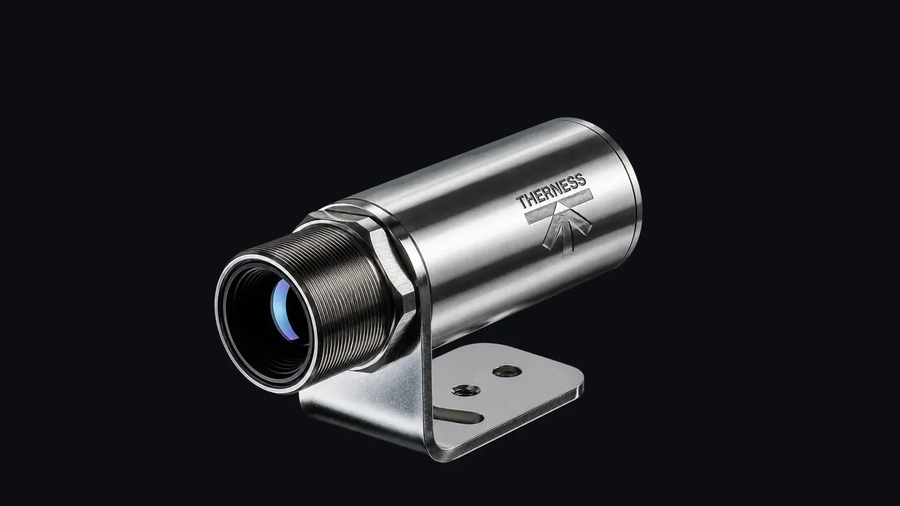
HeatCam IR-C, a cylindrical thermal camera for fixed installations, was built for that profile: a 384 × 240 radiometric sensor covering -20 °C to 900 °C (1500 °C with the optional range) at 60 mK sensitivity, so one device reads both a hot billet and a warm die face; Power over Ethernet and Modbus so it lands on the plant network over one cable; remote motorised focus and a choice of lenses so the working distance stays clear of spray and scale. Where there is no room for a full-size housing, the compact HeatCam IR-S covers the same measurement.
Step-by-step implementation
Step 1 — Decide the question before the hardware
Write down the decision the data will support: extend die life, cut underfill scrap, prove stock temperature to a customer, shorten warm-up. Each implies a different viewpoint and sampling rate. An installation without a stated question produces an archive, not a control.
Step 2 — Choose the viewpoint
Pick the position that sees the region of the impression where the process is most sensitive, at an angle as close to normal as the cell allows. Steep angles depress apparent emissivity and add reflections. Confirm the die is genuinely visible at that moment of the cycle, with the press in every position it reaches.
Step 3 — Fix the geometry and protect it
Mount on structure that does not move when the press strokes. A camera that shifts a few millimetres changes which part of the die each pixel sees, and every trend built on fixed regions of interest silently breaks. Add the enclosure, the air purge and a shielded cable route now, not after the first failure.
Step 4 — Establish emissivity and background in the running state
Bring the cell to normal production condition. Take a contact reference at a defined spot, adjust the emissivity setting until the radiometric reading matches, and measure the reflected apparent temperature from the surroundings as they are during a run. Record both values with the date, the lubricant in use and the die serial.
Step 5 — Define regions of interest and the cycle trigger
Define the areas you will trend: typically the deepest part of the impression, a flash land, and a reference area away from contact. Trigger measurement from the press signal so every cycle is sampled at the same phase. Untriggered sampling mixes peaks and troughs and turns a clean signal into noise.
Step 6 — Set alarms from observed behaviour
Run the cell long enough to characterise normal variation, then set warning and action levels from that record. Alarms invented before the baseline exists are ignored within a week, or they stop the press for nothing.
Step 7 — Join the thermal record to production data
Stamp every record with part number, die serial, cycle count and shift. This converts a monitoring system into an engineering asset: die life becomes explainable, and a scrapped batch can be checked against what the die was doing. Software such as HeatCore Basic takes the camera stream and turns it into alarms, statistics and a durable record.
- Viewpoint sees the sensitive region at a near-normal angle, in every press position
- Mounting is off the press frame and does not move under stroke
- Window purge running, air supply clean and dry
- Emissivity and reflected apparent temperature measured in the running state and recorded
- Cycle trigger wired from the press, not from a timer
- Regions of interest defined, named and documented with a reference image
- Baseline production run captured before any alarm level is set
- Reference check procedure written, with the responsible role named
- Records carry part number, die serial and cycle count
Failure modes and fixes
Fixed thermography fails in a small number of recognisable ways, and knowing the signature is what lets an operator separate an instrument problem from a process problem.
| Symptom in the data | Likely cause | Fix |
|---|---|---|
| Slow downward drift over a shift, recovering after cleaning | Lens or window contamination by scale, smoke or lubricant mist | Restore or increase the air purge, add cleaning to the shift routine |
| Step change after maintenance, no process change | Camera moved, refocused, or regions of interest shifted | Re-establish geometry from the reference image, re-verify against contact |
| Edges of the impression read cold, centre normal | Steep viewing angle reducing apparent emissivity at the edges | Move the viewpoint closer to normal or split the field between two positions |
| Readings jump when a furnace door opens | Reflected apparent temperature not compensated | Re-measure the background in the real condition, shield the line of sight |
| Sharp dips right after lubricant spray | Steam plume attenuating the path, not a real die temperature | Move the sampling phase or the viewpoint out of the plume |
| Whole field reads high after a coating change | Emissivity value now wrong for the new surface | Re-determine emissivity in the running state, record the new value |
| One region diverges permanently from the rest | Real process change: die wear, cracked insert, blocked nozzle | Inspect the die; this is the case the system exists to find |
The last row is the point of the exercise. Every other row is an instrument fault dressed as a process fault, which is why the verification routine matters more than the camera specification.
Verification, traceability and payback
Reference checks
The simplest effective routine is a repeatable comparison: a target of known, stable temperature held in the field of view at a fixed position and read at the start of every run. Any deviation is an instrument or path problem, because the reference has not changed.
Traceability and competence
For a measurement that leaves the plant — a customer requirement on stock temperature, for example — the chain has to reach a recognised reference. The national metrology institutes are the authority: the NIST radiation thermometry programme, the temperature and humidity work at NPL and the Consultative Committee for Thermometry at the BIPM each publish the basis such a chain is built on. The equivalent discipline for welding measurement is set out in the guidance on calibration, verification and validation of monitoring equipment. Language matters too: ISO 10878 defines the vocabulary of infrared thermography for non-destructive testing, and a plant that uses “apparent temperature” loosely will eventually argue about a number that was never in dispute. Qualification routes and method papers live with the professional bodies, notably the American Society for Nondestructive Testing and the open technical literature at NDT.net.
Where the money comes back
Once the measurement is trustworthy, treat it as a process variable rather than an alarm source: control charts on peak die temperature per cycle expose drift long before a threshold is crossed, as described for statistical process control on thermographic data. Two uses pay back consistently. A warm-up schedule sized for the worst case can be replaced by a measured condition, recovering press time. And when a die carries a thermal history alongside its cycle count, the link between thermal excursions and observed wear becomes measurable rather than anecdotal, which makes a refurbishment interval defensible.
Sector background sits with the Forging Industry Association, the European federation EUROFORGE and, for die materials and hot working, ASM International; plant conditions the installation must live in are covered by the HSE guidance on metalworking. Active techniques for subsurface evaluation, as opposed to process monitoring, sit on the thermography and NDT testing hub and in the article on infrared thermography for real-time quality.
FAQ
What temperature range does a forging die monitoring camera need to cover?
It has to span two very different targets: the billet leaving the furnace, which is near the top of the hot-working range for the alloy, and the die face between blows, which is far cooler. A single radiometric camera with a wide calibrated range covers both without swapping optics.
How do you set emissivity for a scaled forging die surface?
Do not take a handbook value. Heat the die to a known, stable state, read it with a contact sensor at the same spot, then adjust the emissivity setting until the radiometric reading agrees. Repeat after any change of coating, lubricant or scale condition, and record the value used.
Can a fixed thermal camera survive inside a hot forging bay?
Yes, with the right enclosure and siting. The camera needs a sealed housing, a clean-air purge across the window, mounting off the press frame to avoid shock, and a viewing path that is not in the direct line of scale, lubricant spray or descaling water.
How often should a die temperature monitoring installation be verified?
Run a short reference check every shift or every production run, whichever is shorter, and a full comparison against a traceable reference on a documented interval. A daily check catches window contamination and focus drift long before it distorts a trend.
Does thermography replace thermocouples embedded in the die block?
No. Embedded thermocouples read bulk die temperature at one depth and one point; thermography reads the surface across the whole impression. They answer different questions, and the strongest installations keep both and cross-check one against the other.
What thermal pattern points to a failing die lubricant spray?
A spray fault shows as a stable geometric cold or hot region that repeats in the same place on every cycle. Blocked nozzles leave a hot band where cooling is missing; a stuck-open nozzle leaves a persistent cold patch and often a slow downward drift of the whole die face.
How many cameras does one forging press cell usually need?
Start with one on the die face and add a second on the billet transfer only if stock temperature is a known variable. More cameras multiply calibration and cleaning work, so add a viewpoint only when it answers a question the first one cannot.
Which standards govern infrared thermography used for process monitoring?
ISO 18434-1 sets out general procedures for thermography in condition monitoring, including compensation for emissivity, reflected apparent temperature and attenuating media. ISO 18251-1 describes system and equipment characteristics, and ISO 10878 fixes the vocabulary.
Put a number on what your dies are doing
Tell us the press, the cycle time and the space around the die, and we will come back with a viewpoint, an optics choice and a verification routine you can run on a shift.
Discuss a forging cell installationFrequently Asked Questions
What temperature range does a forging die monitoring camera need to cover?
It has to span two very different targets: the billet leaving the furnace, which is near the top of the hot-working range for the alloy, and the die face between blows, which is far cooler. A single radiometric camera with a wide calibrated range covers both without swapping optics.
How do you set emissivity for a scaled forging die surface?
Do not take a handbook value. Heat the die to a known, stable state, read it with a contact sensor at the same spot, then adjust the emissivity setting until the radiometric reading agrees. Repeat after any change of coating, lubricant or scale condition, and record the value used.
Can a fixed thermal camera survive inside a hot forging bay?
Yes, with the right enclosure and siting. The camera needs a sealed housing, a clean-air purge across the window, mounting off the press frame to avoid shock, and a viewing path that is not in the direct line of scale, lubricant spray or descaling water.
How often should a die temperature monitoring installation be verified?
Run a short reference check every shift or every production run, whichever is shorter, and a full comparison against a traceable reference on a documented interval. A daily check catches window contamination and focus drift long before it distorts a trend.
Does thermography replace thermocouples embedded in the die block?
No. Embedded thermocouples read bulk die temperature at one depth and one point; thermography reads the surface across the whole impression. They answer different questions, and the strongest installations keep both and cross-check one against the other.
What thermal pattern points to a failing die lubricant spray?
A spray fault shows as a stable geometric cold or hot region that repeats in the same place on every cycle. Blocked nozzles leave a hot band where cooling is missing; a stuck-open nozzle leaves a persistent cold patch and often a slow downward drift of the whole die face.
How many cameras does one forging press cell usually need?
Start with one on the die face and add a second on the billet transfer only if stock temperature is a known variable. More cameras multiply calibration and cleaning work, so add a viewpoint only when it answers a question the first one cannot.
Which standards govern infrared thermography used for process monitoring?
ISO 18434-1 sets out general procedures for thermography in condition monitoring, including compensation for emissivity, reflected apparent temperature and attenuating media. ISO 18251-1 describes system and equipment characteristics, and ISO 10878 fixes the vocabulary.