Infrared monitoring of heat treatment and quenching lines answers a question no furnace controller can: what temperature the part was at when the process step actually happened. A furnace thermocouple reports the atmosphere near its own tip; a load thermocouple reports one bolted point. Between those two readings sits everything that decides whether a welded fabrication leaves the line with the microstructure its procedure assumed — soak uniformity across a heavy section, the temperature lost during the move to the quench tank, and how evenly the quenchant wets the surface.
Key takeaways
- A furnace setpoint is a control variable, not evidence about the part.
- Four stations carry almost all the value: furnace exit, transfer path, quenchant entry, post-quench.
- Emissivity is not a material constant here: it moves with oxide growth, so a fixed value drifts through the cycle.
- Steam and quench vapour dominate the error at the tank; design the geometry to avoid them.
- Contact thermocouples stay the calibrated reference; infrared adds coverage between and beyond them.
- The transfer delay from furnace exit to quenchant entry is assumed, never measured, and cheap to expose.
Table of Contents
- What Infrared Adds That Thermocouples Cannot
- The Four Stations on a Heat Treat and Quench Line
- Getting the Radiometry Right
- Failure Modes and How to Fix Them
- Implementing a Station, Step by Step
- Verification: Proving the Record Is True
- Where This Sits in a Fabrication Quality System
- Frequently Asked Questions
What infrared adds that thermocouples cannot
The gap between a furnace setpoint and a part surface
A heat treatment procedure specifies temperatures for the workpiece, but the furnace is controlled from its own sensors, and the correction between the two is set once in a uniformity survey and trusted for months. Reasonable for a stable load; unreasonable as soon as the load changes — a heavier weldment, a denser stack, a fixture that shadows one face.
Infrared imaging makes the load itself the measurement. An image at the door shows the real surface distribution: which end of a long fabrication is trailing, whether a thick node is still cold while the plate around it is at temperature, whether the fixture is acting as a heat sink.
Where the load, not the furnace, decides the outcome
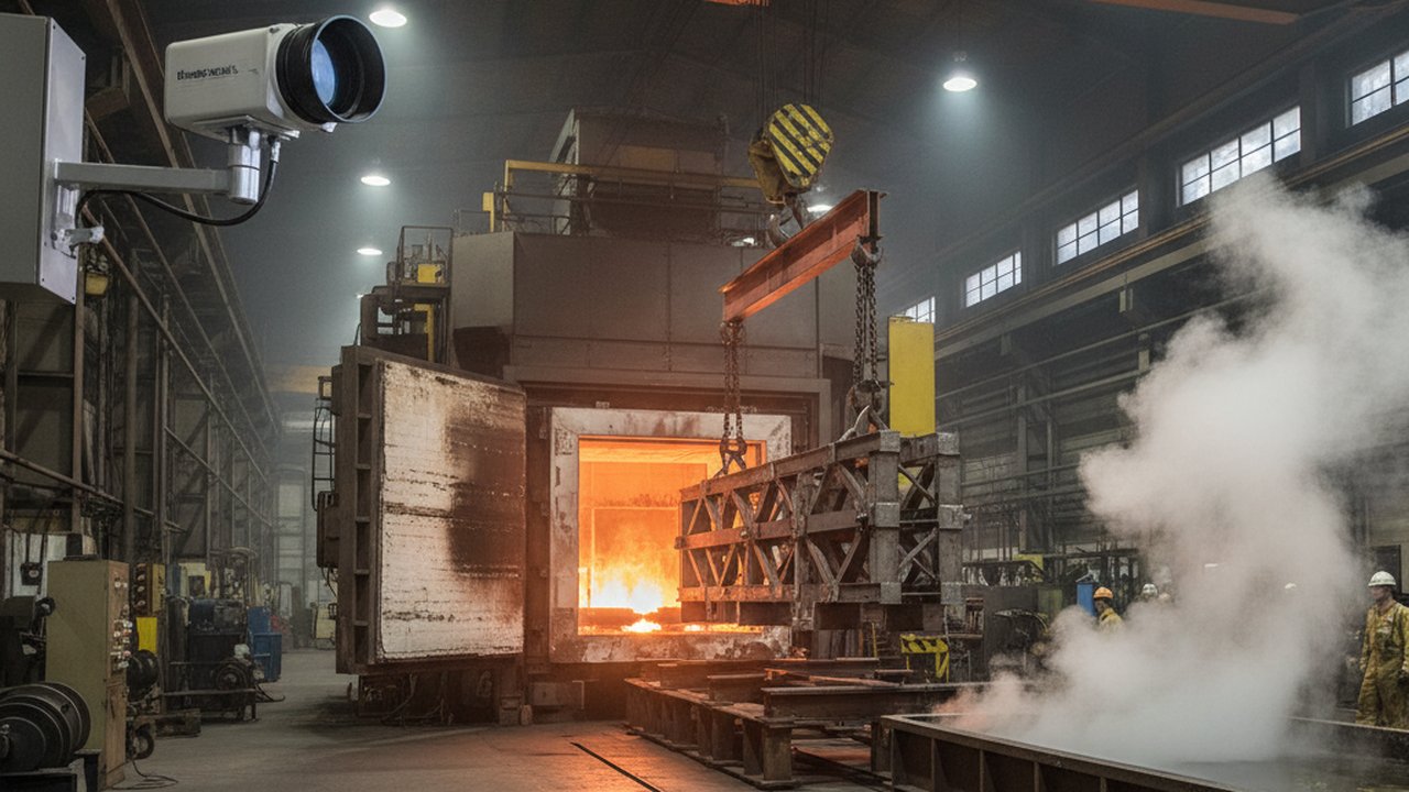
Quenching is the clearest case. Once the part leaves the furnace nothing measures it: the transfer is timed by procedure, and the assumption that the surface was still hot enough at immersion is never tested. One fixed camera on the transfer path turns that assumption into two logged numbers per load — how long the move took, and what it cost in surface temperature. The discipline behind in-process imaging with a welding camera transfers cleanly here: same physics, different time constants and range.
Infrared does not make a thermocouple redundant. It makes the space between thermocouples measurable, and follows the part where a wired sensor cannot go.
The four stations on a heat treat and quench line
| Station | Question it answers | What invalidates it | Practical note |
|---|---|---|---|
| Furnace exit | Did the whole load reach and hold temperature, or only the outside of the stack? | Door radiation reflecting off the part; view blocked by the charge car | Frame the load face-on as the door opens |
| Transfer path | How much surface temperature was lost between furnace and quenchant? | Crane path drifts out of the field of view; operators change the route | Fix the camera to the structure, not the crane |
| Quenchant entry | Did the part enter hot enough, and did the surface wet evenly? | Steam and vapour between lens and part | Measure immediately before immersion; readings through the vapour cloud are indicative only |
| Post-quench / temper | Is the part uniform coming out, and did tempering reach the whole section? | Wet surface with variable emissivity; residual quenchant film | Let the surface dry, or read it as a comparative map |
Most lines gain most from the transfer path first, because nothing measures it today; furnace exit comes second, validating the survey correction against real loads rather than a survey fixture.
Getting the radiometry right
Emissivity moves with oxide, not with alloy
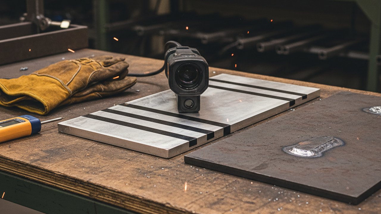
The most common commissioning error is treating emissivity as a property of the alloy. It is a property of the surface, and here the surface changes during the cycle. Bright machined or shot-blasted steel is a poor, unstable radiator whose low emissivity varies strongly with viewing angle. As oxide grows, emissivity rises substantially and becomes far more stable and much less angle-sensitive.
So a camera commissioned on clean stock will not agree with itself on a scaled load at the same true temperature. Two defences work: commission emissivity on the surface condition the part will actually have at that station, and where the surface changes within one cycle, choose a geometry that reduces emissivity sensitivity rather than compensating in software afterwards.
Wavelength band is a design decision, not a default
At elevated temperature, radiance changes far more steeply with temperature at short wavelengths than at long ones — a consequence of Planck’s law, and the reason short-wave instruments dominate high-temperature pyrometry. An emissivity error therefore produces a smaller temperature error at short wavelengths; NIST’s thermometry programme publishes the background. The trade: short-wave buys immunity to emissivity uncertainty but needs a threshold temperature, while long-wave reaches ambient and pays in emissivity sensitivity. A line covering a red-hot furnace exit and a near-ambient post-quench check needs two stations, not one compromise camera.
Steam, smoke and windows
Water vapour and carbon dioxide absorb infrared in specific bands, so the medium between part and lens is never neutral. At a quench tank that is not a subtle correction: steam from a water quench, or vapour and smoke from an oil quench, can dominate the signal. A camera aimed through a rising vapour column is measuring the vapour.
Three mitigations: shorten or remove the vapour path; measure immediately before immersion; and where a furnace port view is unavoidable, characterise the window’s transmission at commissioning. A window with an oil film is an unrecorded offset on every later measurement.
Failure modes and how to fix them
Readings drift upward over a campaign with no process change. Usually oxide growth or a fouled window. Re-check emissivity against an instrumented load, and put window cleaning on a defined interval rather than a judgement call.
A furnace-exit image shows a hot rim and cold centre that metallurgy does not confirm. Normally reflected radiation from the furnace interior arriving off the part surface. Image the part after it clears the door aperture, at an angle where the specular reflection of the furnace mouth misses the lens.
Transfer temperature loss varies wildly load to load. Almost always a real process variable — crane speed, hook height, whether the operator paused. The most useful failure mode of the four: visible, attributable, fixable by changing the move rather than the metallurgy.
Post-quench maps look uniform but hardness testing disagrees. A wet surface reads more uniform than the steel beneath it, because the liquid film equalises the apparent surface. Measure after drying, or treat the station as a comparative check only.
One thick node never reaches temperature. Not an instrument failure — the camera found a soak problem the furnace controller could not see. The fix belongs to loading pattern and soak time; the same reasoning for weld-adjacent heating is in the guide to preheat and interpass temperature monitoring under ISO 13916.
When infrared disagrees with a thermocouple, the first hypothesis is a measurement error and the second is that the camera is right about a place the thermocouple never represented. Both happen; the instrumented-load test separates them.
Implementing a station, step by step
- Write the question first — soak uniformity, transfer loss, entry temperature, post-quench uniformity. A station without a question produces images nobody reads.
- Fix the geometry. Mount on building structure, sightline unobstructed, incidence angle as near perpendicular as the layout allows, standoff outside the thermal and vapour plume.
- Size the field of view for the worst case — largest load, longest crane path. A station that loses the part on a bad day fails when the data mattered.
- Specify band and range from the temperatures that station will see. Do not stretch one camera across the line.
- Commission emissivity on the real surface condition, recording value, surface state and date as station configuration.
- Define the trigger. Capture on an event — door open, beam break, immersion — not free-run, so the record stays aligned to the process step and retrievable by load number.
- Bind data to the load identity. A record that cannot be traced to a charge and part number is an image, not evidence.
- Alarm on the process question, not the raw pixel. “Transfer loss exceeded the qualified window” is actionable; “a pixel crossed a threshold” produces alarm fatigue within a week.
- Validate against an instrumented load before trusting the station, then on schedule and after any change to optics, geometry or surface preparation.
For welded assemblies treated after fabrication, sequencing and record structure carry over from post-weld heat treatment thermal monitoring; the cooling-rate arithmetic behind the specification can be checked with the t8/5 cooling time calculator and the preheat temperature calculator.
Verification: proving the record is true
The instrumented load
The reference test is a part carrying calibrated contact thermocouples through the same cycle the camera watches, both traces on a common clock. Compare at matched points and times and report the residual. That residual — not the datasheet — is the accuracy of the station as installed, window, angle and emissivity included. Repeat whenever one of those changes.
Drift and calibration discipline
Pyrometry practice in regulated heat treating rests on three recurring activities: instrument calibration, system accuracy testing, and temperature uniformity surveys. SAE AMS2750 formalises them for aerospace furnaces, ovens, salt baths and vacuum furnaces; the automotive supply chain works to equivalent discipline through AIAG’s CQI-9 heat treat system assessment. Neither was written with imaging in mind, but the structure they impose is what makes an infrared station a measurement rather than a picture. On the imaging side, ISO 18434-1 is written for machinery condition monitoring, but its procedures for reflected apparent temperature, emissivity and attenuating media transfer directly to a heat treatment line — a framework to borrow, not a specification to comply with.
What an auditor actually asks
What was the reference, when was it last compared, and can you retrieve the record for this load. A station answering all three is defensible; thermal video with no link to a charge number is not — the same evidence logic that runs through thermography NDT testing.
Standards that govern the record
- ISO 17663 gives quality requirements for heat treatment carried out in workshops and on site in connection with welding and allied processes — how the operation is specified, resourced and recorded.
- ISO 13916 specifies requirements for measuring preheating, interpass and preheat maintenance temperature in fusion welding, and explicitly excludes post-weld heat treatment temperatures from its scope — a boundary routinely cited for the wrong step.
- The ASME Boiler and Pressure Vessel Code carries the post-weld heat treatment requirements most pressure equipment work is built around.
Alongside the codes, ASNT covers personnel qualification for the imaging and NDT side, and journals such as Infrared Physics and Technology carry the measurement science behind where preheat, interpass and post-heat temperatures are actually taken.
Where this sits in a fabrication quality system
A heat treatment station rarely pays alone. It earns its place when its record joins the other evidence for the same part — welding parameters, thermal history, distortion behaviour — which argues for treating heat treatment as one instrumented step inside a welding monitoring system rather than an isolated furnace log, on the same data model as thermal monitoring of weld distortion.
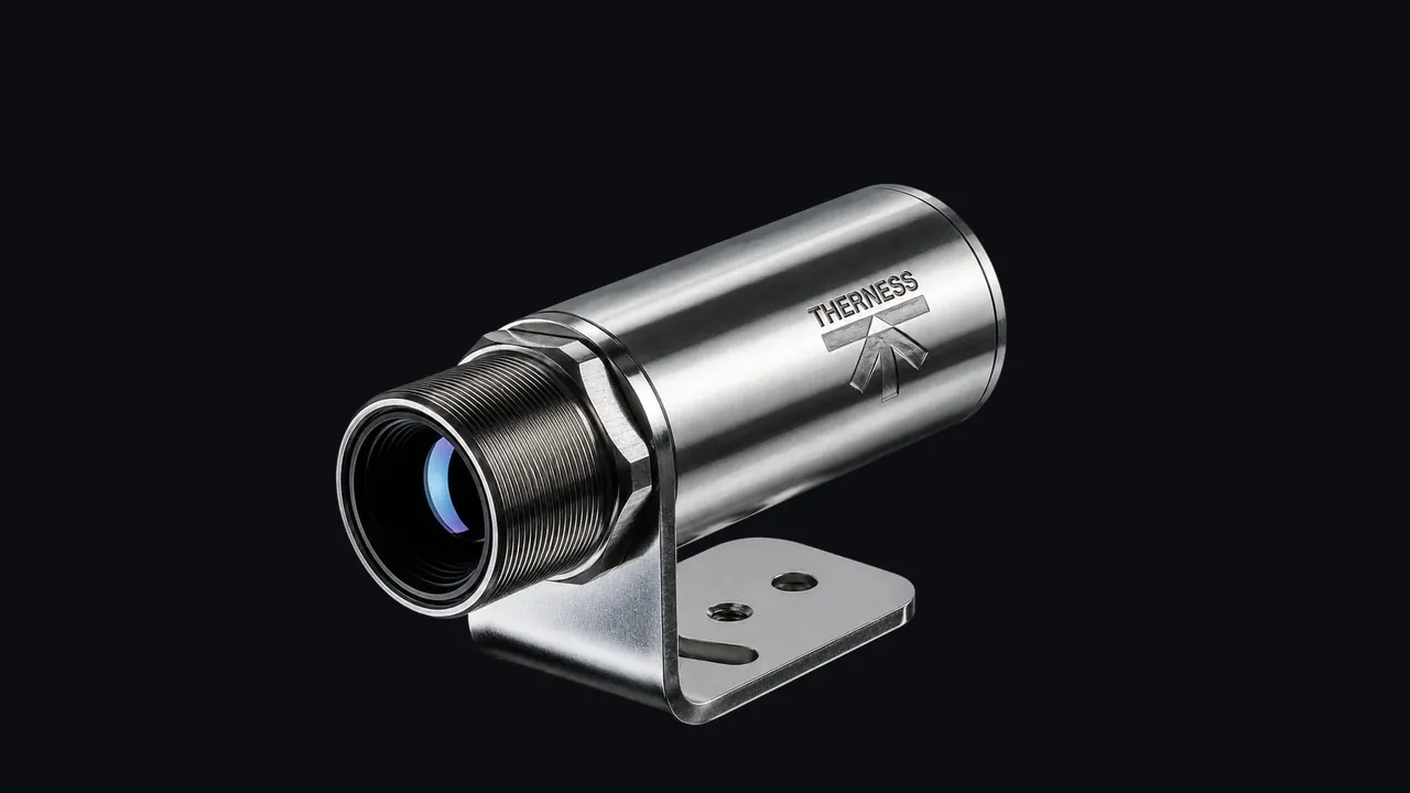
The hardware profile follows: rugged housing, a documented and unchanging optical configuration, event-triggered radiometric capture, and an output a plant system consumes without a human retyping numbers. That is the role the HeatCam IR-C cylindrical thermal camera is built for.
Frequently Asked Questions
Can an infrared camera replace furnace load thermocouples for heat treatment records?
Not on its own. A load thermocouple is the traceable contact reference and stays the instrument of record. An infrared station adds full-surface coverage between the thermocouple points and outside the furnace, where no thermocouple can follow the part. Treat the camera as coverage, the thermocouple as the reference.
Why does a quenched part often read colder on a thermal image than it actually is?
Because the surface stops being a clean radiator. Steam, quench oil vapour and a wet or boiling liquid film sit between the part and the lens, absorbing and scattering the signal. The camera reports the temperature of what it can see, which during a quench is often the vapour layer rather than the steel underneath.
Where should a thermal camera be placed on a quench transfer line?
On the transfer path, framing the part between furnace exit and quenchant entry, with the optical axis as close to perpendicular to the main surface as the layout allows. That station answers the question a furnace controller cannot: how much surface temperature the load lost while it was being moved.
What problem does oxide scale create for infrared heat treatment monitoring?
Scale changes emissivity as it grows, so a fixed emissivity setting drifts through the cycle. Bright machined steel is a poor, unstable radiator; heavily oxidised steel is a good and much more stable one. A camera commissioned on clean stock will read a scaled load differently even at identical true temperature.
How do you monitor the transfer delay between furnace exit and quenchant entry?
Timestamp the frame where the part clears the furnace door and the frame where it breaks the quenchant surface, and log surface temperature at both. The delay and the temperature lost across it become two recorded process variables instead of an assumption written into the procedure and never measured again.
Does ISO 17663 apply to heat treatment carried out after welding?
Yes. ISO 17663 sets quality requirements for heat treatment performed in workshops and on site in connection with welding and allied processes, covering how the operation is specified, controlled and recorded. It governs the conduct of the treatment, not the acceptance limits of the welded joint itself.
How is an infrared heat treatment record validated against a calibrated reference?
By running an instrumented load: a part carrying calibrated contact thermocouples through the same cycle the camera watches, then comparing the two traces at matched points and times. The residual between them is the number for the validation report, repeated whenever optics, geometry or surface condition change.
Instrument your heat treatment line
Tell us the loads, the transfer path and the quench you run, and we will map which infrared stations pay back first and what the record would look like.
Discuss a heat treat monitoring stationFrequently Asked Questions
Can an infrared camera replace furnace load thermocouples for heat treatment records?
Not on its own. A load thermocouple is the traceable contact reference and stays the instrument of record. An infrared station adds full-surface coverage between the thermocouple points and outside the furnace, where no thermocouple can follow the part. Treat the camera as coverage, the thermocouple as the reference.
Why does a quenched part often read colder on a thermal image than it actually is?
Because the surface stops being a clean radiator. Steam, quench oil vapour and a wet or boiling liquid film sit between the part and the lens, absorbing and scattering the signal. The camera reports the temperature of what it can see, which during a quench is often the vapour layer rather than the steel underneath.
Where should a thermal camera be placed on a quench transfer line?
On the transfer path, framing the part between furnace exit and quenchant entry, with the optical axis as close to perpendicular to the main surface as the layout allows. That station answers the question a furnace controller cannot: how much surface temperature the load lost while it was being moved.
What problem does oxide scale create for infrared heat treatment monitoring?
Scale changes emissivity as it grows, so a fixed emissivity setting drifts through the cycle. Bright machined steel is a poor, unstable radiator; heavily oxidised steel is a good and much more stable one. A camera commissioned on clean stock will read a scaled load differently even at identical true temperature.
How do you monitor the transfer delay between furnace exit and quenchant entry?
Timestamp the frame where the part clears the furnace door and the frame where it breaks the quenchant surface, and log surface temperature at both. The delay and the temperature lost across it become two recorded process variables instead of an assumption written into the procedure and never measured again.
Does ISO 17663 apply to heat treatment carried out after welding?
Yes. ISO 17663 sets quality requirements for heat treatment performed in workshops and on site in connection with welding and allied processes, covering how the operation is specified, controlled and recorded. It governs the conduct of the treatment, not the acceptance limits of the welded joint itself.
How is an infrared heat treatment record validated against a calibrated reference?
By running an instrumented load: a part carrying calibrated contact thermocouples through the same cycle the camera watches, then comparing the two traces at matched points and times. The residual between them is the number for the validation report, repeated whenever optics, geometry or surface condition change.