Partial penetration welds (PJP) appear in virtually every structural and mechanical fabrication — yet they are among the most mis-specified, misdetected, and poorly documented joint types in production welding. The effective throat depth governs load-carrying capacity: a deviation of a few millimetres separates a compliant joint from a critical failure mode. Understanding when to specify a PJP weld, how to design it to AWS D1.1 or EN 1090 requirements, which acceptance criteria apply under ISO 5817, and which NDE methods reliably assess the root is essential for welding engineers, quality managers, and structural inspection teams.
Key Takeaways
- Effective throat — not groove depth — governs load capacity; AWS D1.1 deducts 3 mm for groove angles below 45°.
- ISO 5817 Levels B and C prohibit incomplete penetration where full penetration was specified by the designer — document design intent clearly in the weld map.
- PJP welds in cyclic-tension Category E connections are prohibited under AWS D1.1 fatigue provisions; verify the stress range before specifying PJP.
- Phased Array UT and TOFD outperform conventional pulse-echo UT for root assessment in PJP grooves.
- Weld maps must record specified minimum effective throat alongside WPS reference, position, and measured result.
- Thermal monitoring of heat input during PJP welding reduces the risk of incomplete fusion at the unfused root face by keeping the process within the qualified parameter envelope.
Table of Contents
- What Is a Partial Penetration Weld?
- Joint Design Rules for PJP Welds
- Acceptance Criteria: ISO 5817, AWS D1.1 and ASME
- NDE Inspection of Partial Penetration Joints
- Common Failure Modes and Root Causes
- Documentation and Traceability
- Frequently Asked Questions
What Is a Partial Penetration Weld?
A partial penetration weld (PJP) — also called a partial joint penetration weld — is a groove weld in which the weld metal does not extend through the full thickness of the joint. The unfused portion of the base metal at the root is an intentional design feature, not a defect, provided it meets the dimensional and quality requirements of the applicable standard.
PJP welds are used when:
- The full cross-section is not required for the applied loads (e.g., column-to-baseplate connections in compression)
- Joint geometry or restricted access prevents complete fusion from one side, and back-gouging is not feasible or economical
- The design standard explicitly permits PJP for that joint type, loading, and execution class
PJP vs Complete Joint Penetration (CJP) Welds
| Property | PJP Weld | CJP Weld |
|---|---|---|
| Root fusion | Partial — designed unfused portion | Complete through-thickness |
| Load path | Governed by effective throat | Full joint cross-section |
| Typical application | Compression, shear, secondary members | Tension, fatigue, pressure boundary |
| NDE root access | Root zone difficult to assess | Root can be examined from opposite face |
| Fatigue category (AWS D1.1) | Category E (tension) | Category B–C |
Effective Throat: The Critical Dimension
The effective throat is the shortest distance from the weld root to the weld face, measured perpendicular to the weld face. It is NOT the bead depth or groove depth alone — it is the dimension that governs every stress and load capacity calculation.
AWS D1.1 deduction rule: For groove angles below 45°, deduct 3 mm (1/8 in) from the groove depth to obtain the effective throat. For angles between 45° and 60°, groove depth equals effective throat. Above 60°, effective throat may be taken as groove depth with qualification testing per AWS D1.1:2020 clause 7.
EN ISO 9692 series specifies the minimum effective throat for each groove type; the weld designer must demonstrate that the specified groove geometry achieves the required throat under production conditions at the qualified heat input.
Joint Design Rules for PJP Welds
PJP joints must be fully detailed in the WPS and clearly labelled on drawings with the specified minimum effective throat. Design is governed by the applicable fabrication standard.
Prequalified PJP Joints per AWS D1.1
AWS D1.1:2020 Table 4.13 lists prequalified PJP groove weld joint details (J-series and K-series) that do not require separate procedure qualification testing, provided all prequalification parameters are met:
- Groove angle: minimum 45° (single-V) or 30° each side (double-V) for prequalification
- Root face: minimum 3 mm for joints without backing
- Base metal: only pre-approved P-number/S-number groups per AWS D1.1 Annex I
- Process: SMAW, GMAW, FCAW, SAW in specified transfer modes only
- Position: as listed in Table 4.13 for each joint type
Deviating from any prequalification limit requires a full WPQR per AWS D1.1 Clause 7.
EN 1090 and EN 15085 Design Requirements
Under EN 1090-2 (execution of steel structures) and EN 15085 (railway rolling stock welding), PJP welds are classified by execution class:
- EXC2 and above (EN 1090-2): PJP welds carrying tension require design justification and enhanced inspection frequency relative to CJP joints.
- EN 15085 CP-C1: PJP welds for structural primary joints must meet CP-B1 weld quality criteria; CP-D (secondary) joints allow relaxed quality requirements.
- For railway applications, the design engineer must document whether a PJP joint is acceptable for the component fatigue class and certify the minimum effective throat on the component drawing.
Effective Throat Verification Through WPS Qualification
A WPS for a PJP groove weld must be qualified to the minimum effective throat specified on the design drawing. Macro cross-sections from the qualification test assembly under ISO 15614-1 must confirm the achieved throat depth. The qualification record (WPQR) must show that production welding parameters remain within the qualified range; heat input excursions outside this range can reduce the actual throat without any visible surface indicator. Continuous thermal process monitoring flags these heat-input excursions in real time.
Effective throat is a geometry outcome, not just a drawing requirement. A WPS that passes qualification but is run at the lower end of the heat input range in production may consistently undercut the specified minimum throat — invisible to surface inspection alone.
Acceptance Criteria: ISO 5817, AWS D1.1 and ASME
Acceptance criteria for PJP welds depend on the applicable product standard and inspection class. The critical distinction is always between the designed unfused root (acceptable) and unintended incomplete penetration (a non-conformity in any level).
ISO 5817 Quality Levels
ISO 5817:2023 (Fusion-welded joints in steel — Quality levels for imperfections) applies to the weld geometry above the designed unfused root:
| Imperfection Type | Level B (Stringent) | Level C (Intermediate) | Level D (Moderate) |
|---|---|---|---|
| Incomplete penetration beyond design | Not permitted | Not permitted | ≤ 0.2t or 2 mm max |
| Undercut at weld toe | ≤ 0.5 mm | ≤ 1 mm | ≤ 1.5 mm |
| Root concavity (single-sided weld) | 0 mm | ≤ 0.5 mm | ≤ 1 mm |
| Excess weld metal crown | ≤ 1 mm + 0.1b | ≤ 2 mm + 0.1b | ≤ 3 mm + 0.1b |
Critical distinction: If a joint is designed as PJP, the unfused root portion is NOT an imperfection. The inspector must verify from the engineering drawing or WPS whether the joint was designed as PJP or whether incomplete penetration in a CJP weld is a non-conformity. Mislabelling design intent on drawings is one of the most common sources of audit non-conformances in ISO 3834 third-party assessments.
AWS D1.1 Visual Acceptance for PJP Welds
AWS D1.1:2020 clause 8 specifies visual inspection acceptance criteria:
- No visible cracks, laps, or incomplete fusion at weld faces
- Undercut ≤ 0.8 mm for primary tension members; ≤ 1.6 mm for secondary members
- Porosity: aggregate diameter ≤ 9.5 mm per 300 mm of weld; no individual pore above 2.4 mm
- Weld size: actual effective throat ≥ specified minimum effective throat, verified by calibrated weld gauge at representative intervals
For NDE, AWS D1.1 Table 9.5 assigns examination requirements based on joint category (tension, compression, shear) and loading type (static, seismic, cyclic). PJP welds in cyclic Category A and B tension connections require UT supplementing VT.
ASME BPVC Requirements
ASME Boiler and Pressure Vessel Code Section IX governs procedure qualification for pressure vessel fabrication. ASME Section VIII Division 1 restricts PJP welds to Category B and C seam joints in compression and shear only; Division 2 permits PJP in non-pressure-boundary attachment welds with designer approval and documented engineering justification. The WPS must reference the applicable Division and the qualified effective throat range.
NDE Inspection of Partial Penetration Joints
NDE of PJP welds presents inherent challenges: the designed unfused root zone can mask true root defects such as lack of fusion, root cracking, or underbead cracking.
Visual Testing Limitations
Per ISO 17637 visual weld inspection requirements, VT can assess weld geometry, surface cracks, undercut, and excess weld metal at the weld face. It cannot assess the root region of a single-sided PJP joint that is not accessible from the back face. VT is necessary but not sufficient for structural PJP welds in fatigue or seismic applications — NDE must follow.
Phased Array UT and TOFD
Phased Array Ultrasonic Testing (PAUT) and Time-of-Flight Diffraction (TOFD) per EN 16714 and ISO 17640 are the preferred NDE methods for PJP root assessment:
- PAUT creates a sectorial scan that maps the weld cross-section, allowing the examiner to distinguish the designed unfused root face from a root lack-of-fusion crack by comparing signal position against the known groove geometry.
- TOFD measures time of flight between a diffracted signal at a defect tip and the structural response from the backwall; it quantifies defect height independently of orientation — critical when root cracks grow parallel to the fusion line.
Both methods require calibration blocks that reproduce the PJP groove geometry and a written NDE procedure qualified per ISO 17640. For guidance on comparing NDE methods for complex groove geometries, TWI provides independent technical assessments that are widely referenced in European inspection specifications.
Radiographic Testing Limitations
RT is poorly suited to PJP root assessment. The projection geometry that gives RT its sensitivity to planar defects perpendicular to the beam fails for root lack-of-fusion running parallel to the beam. Cracks at the PJP root growing parallel to the weld axis may be entirely invisible on a radiograph regardless of film type or source geometry. For joints where root quality is critical, supplement or replace RT with PAUT or TOFD.
Radiography can confirm the weld is present and characterise volumetric indications such as porosity or slag. It cannot reliably characterise root lack-of-fusion in a PJP groove — this is a fundamental physics limitation, not an equipment quality issue. Specify PAUT or TOFD when root soundness is structurally critical.
Common Failure Modes and Root Causes
Understanding the most common PJP failure modes directs both WPS development and inspection planning.
Lack of Fusion at Root
The most frequent PJP failure mode: weld metal solidifies above the designed root without fusing to the groove side walls, creating a planar defect that mimics the designed root interface. Root causes include:
- Groove angle too narrow for the wire or electrode diameter — the arc cannot reach the groove walls
- Heat input below the minimum WPS limit, especially relevant in SAW where current variation can starve the root
- Joint fit-up out of tolerance — excessive root face or poor groove preparation reduces the effective melt zone
- Contamination (rust, mill scale, cutting oxide, moisture) at the groove base
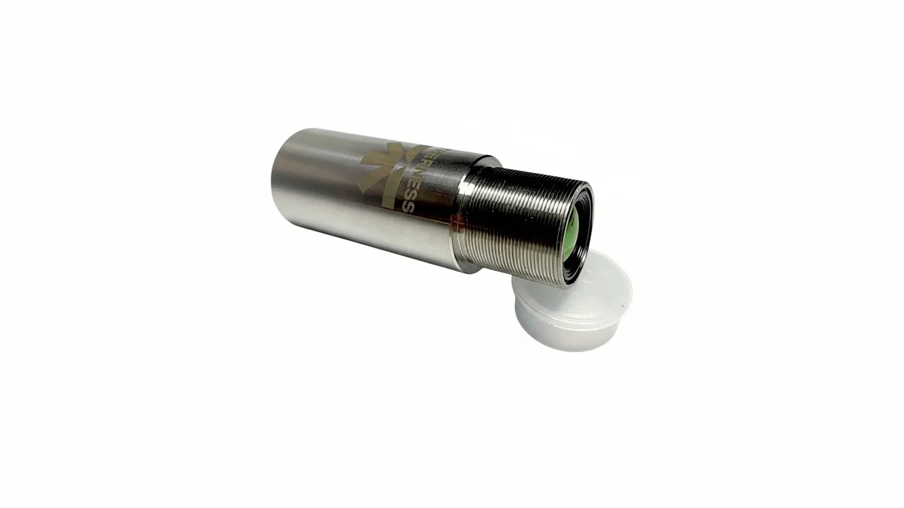
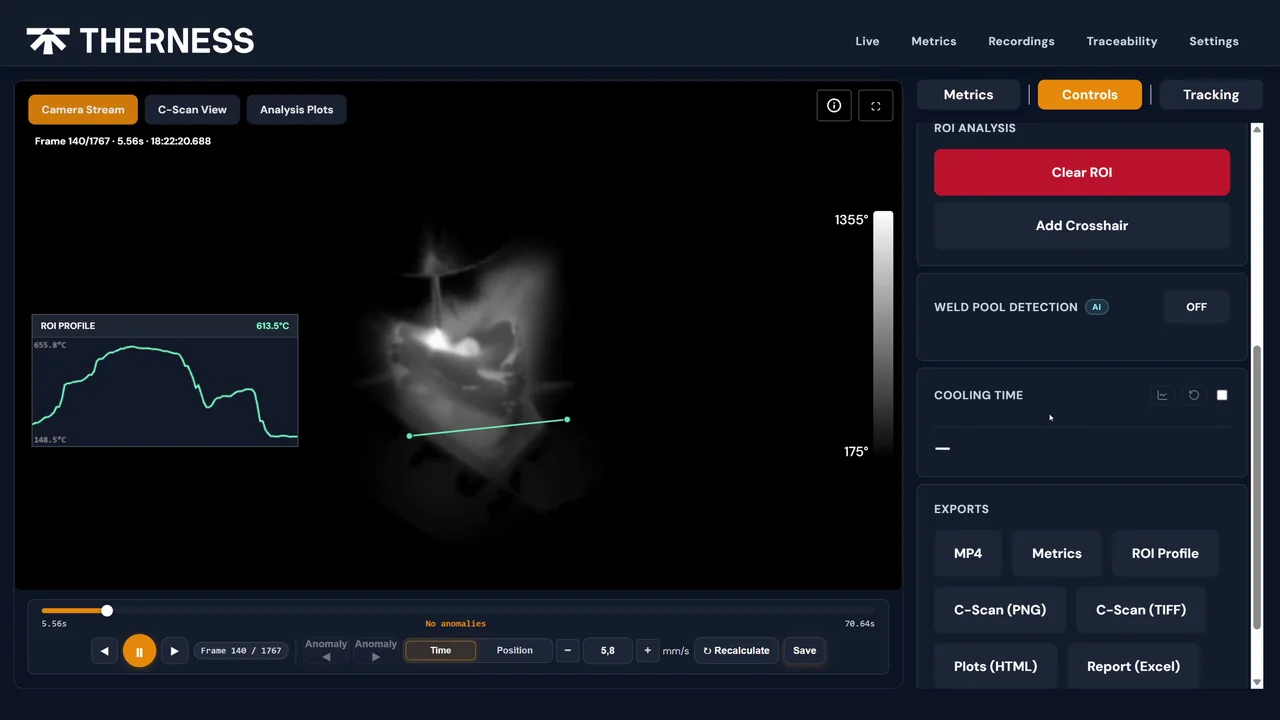
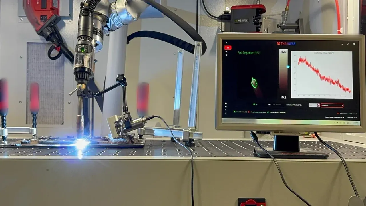
Mitigation: real-time weld process monitoring with thermal imaging during root and fill passes keeps the process within the qualified heat input envelope and generates a time-stamped parameter record for each weld. You can watch thermal imaging of a live weld to see how root-pass heat-input drift shows up in the thermal signature.
Fatigue at the PJP Root
The notch formed at the transition from fused to unfused material concentrates stress under cyclic loading. Fatigue cracks initiate at this notch and propagate perpendicular to the applied stress. AWS D1.1 fatigue provisions assign Category E to PJP groove welds in tension. Structural designers must verify that the connection stress range under the governing load spectrum does not exceed the allowable fatigue stress range for Category E before accepting a PJP design.
For joints that carry primary tension and have a fatigue-sensitive classification, upgrading to CJP eliminates the root notch entirely and typically moves the connection to Category B or C — a substantial improvement in fatigue life.
Root Cracking Under Restraint
High-restraint joints — such as PJP welds on thick flanges, box sections, or structural nodes — are susceptible to hydrogen-induced cracking (HIC) at the root. The designed unfused root face acts as a stress concentrator under shrinkage restraint. Preheat requirements in the WPS must be applied to the full joint cross-section, including the root region, not only to the weld deposit. Refer to EN 1011-2 guidance on hydrogen-controlled welding and to the carbon equivalent (CET) formula for preheat selection.
Root Concavity in Single-Sided PJP Welds
When a PJP weld is deposited from one side into a groove that ends above the back face, weld pool shrinkage on cooling can create a concave root surface. ISO 5817 permits limited root concavity at quality levels C and D; level B requires zero. Torch angle, travel speed, and back-shielding gas (for TIG root passes) must be controlled to minimise shrinkage at the root bead. Review with weld defect acceptance criteria for structural welds.
Documentation and Traceability
A compliant weld record for a PJP joint must capture:
| Field | Source document |
|---|---|
| Weld ID | Drawing / weld map |
| Specified minimum effective throat | Engineering drawing |
| WPS reference | Approved WPS register |
| Welding position | WPS / production traveller |
| Actual effective throat (measured) | Weld gauge record / inspection report |
| VT report reference | ISO 17637 examination record |
| NDE report reference | PAUT/TOFD report (where required) |
| Operator qualification | Welder approval record (ISO 9606-1 / ASME IX) |
Digital traceability systems linked to ISO 3834 and EN 1090 welding quality requirements allow each weld ID on the map to carry a direct link to the WPS, the real-time welding parameter log, and the inspection result. This eliminates transcription errors and supports AS-BUILT documentation for EN 1090 EXC3 and EXC4 delivery packages.
For high-consequence PJP welds — seismic connections, crane runway girders, pressure-boundary nozzle attachments — consider supplementing parameter logs with HeatCam thermal imaging data to confirm interpass temperature compliance and heat input envelope throughout all weld passes. A thermal record keyed to the weld ID provides independent, unbroken evidence that the WPS envelope was maintained pass-by-pass.
Frequently Asked Questions
What is the difference between a partial penetration weld and a full penetration weld?
A partial penetration weld (PJP) does not fuse the complete joint cross-section — the unfused root is an intentional design feature, not a defect. A complete joint penetration (CJP) weld fuses fully through the joint thickness. PJP welds are used for compression-dominant or shear-dominant connections where full penetration is not required by load analysis; CJP is mandated for primary tension loads, fatigue-sensitive connections, and pressure boundaries.
How is effective throat depth calculated for a partial penetration groove weld?
For groove welds, effective throat equals groove depth minus any code-mandated deduction. AWS D1.1 deducts 3 mm from groove depth for groove angles below 45°; groove depth equals effective throat for angles between 45° and 60°. Under EN 1090 and EN ISO 9692, joint-type-specific tables give the minimum effective throat for each groove configuration and welding process. For fillet welds, effective throat = 0.707 × specified leg size.
What are the AWS D1.1 visual acceptance criteria for partial penetration welds?
AWS D1.1 clause 8 requires: no visible cracks; no incomplete fusion at weld faces; undercut ≤ 0.8 mm for primary tension members and ≤ 1.6 mm for secondary members; individual pore ≤ 2.4 mm diameter; aggregate porosity ≤ 9.5 mm per 300 mm weld length; actual effective throat ≥ specified minimum effective throat verified by calibrated weld gauge at representative points.
Can conventional UT detect lack of fusion in a partial penetration weld root?
Conventional pulse-echo UT gives ambiguous results at PJP roots because the designed unfused root face and a root lack-of-fusion crack produce geometrically similar reflections. Phased Array UT (PAUT) and TOFD provide better discrimination by mapping defect tip positions against the known groove geometry and by quantifying defect height independently of orientation — the critical capability when root cracks grow parallel to the fusion line.
Are partial penetration welds permitted in cyclically loaded structures under AWS D1.1?
AWS D1.1 Table 3.5 assigns fatigue Category E to PJP groove welds in tension — one of the lowest allowable fatigue categories. PJP welds are prohibited for cyclic tension connections where the applied stress range exceeds the Category E allowable. Designers must verify the fatigue check before specifying PJP for any dynamically loaded connection; if the check fails, upgrade to CJP or redesign the connection geometry.
What ISO 5817 quality level applies to partial penetration welds?
ISO 5817 quality levels B, C, or D apply to the accessible weld geometry above the designed unfused root. If the joint was designed as PJP, the unfused root is not an imperfection. Incomplete penetration beyond the designed extent is not permitted at levels B and C; at level D, incomplete penetration up to the lesser of 0.2t or 2 mm is tolerated.
When should a partial penetration weld be upgraded to a CJP weld?
Upgrade to CJP when: the joint carries primary tensile loads perpendicular to the weld axis; fatigue governs design and the stress range exceeds the Category E allowable; leak-tightness is required (pressure vessels, piping); or analysis shows the PJP effective throat is insufficient to carry the design loads with the required safety factor under the governing load combination.
How should partial penetration weld depth be recorded in the weld map and quality record?
The weld map must specify for each PJP weld: the weld ID, minimum specified effective throat, applicable WPS reference, welding position, and groove type. The inspection record must capture the measured effective throat at inspection points, the VT result, and any NDE report reference numbers — all linked by weld ID for ISO 3834 and EN 1090 EXC3 documentation packages.
Monitor PJP Weld Heat Input in Real Time
Therness thermal cameras give your welding team live heat input data, interpass temperature alerts, and automatically archived traceability records — for every pass on every PJP joint.
Request a DemoTherness solution: Welding monitoring system — Every weld inspected in the cycle, with defect flags and the ISO 3834 / ISO 17635 evidence kept per weld.
Frequently Asked Questions
What is the difference between a partial penetration weld and a full penetration weld?
A partial penetration weld (PJP) does not fuse the complete joint cross-section — the unfused root is an intentional design feature, not a defect. A complete joint penetration (CJP) weld fuses fully through the thickness. PJP welds are used for compression-dominant or shear-dominant connections; CJP is mandated for primary tension loads, fatigue-sensitive connections, and pressure boundaries.
How is effective throat depth calculated for a partial penetration groove weld?
For groove welds, effective throat equals groove depth minus any code deduction. AWS D1.1 deducts 3 mm from groove depth for groove angles below 45°; groove depth equals effective throat for angles 45–60°. Under EN 1090 / EN ISO 9692, joint-type tables give the minimum effective throat per groove configuration and process. For fillet welds, effective throat = 0.707 × leg size.
What are the AWS D1.1 visual acceptance criteria for partial penetration welds?
AWS D1.1 clause 8 requires: no cracks; no incomplete fusion at weld faces; undercut ≤ 0.8 mm for primary tension members, ≤ 1.6 mm for secondary members; individual pore diameter ≤ 2.4 mm; aggregate porosity ≤ 9.5 mm per 300 mm of weld; actual effective throat ≥ specified minimum effective throat verified by weld gauge.
Can conventional UT detect lack of fusion in a partial penetration weld root?
Conventional pulse-echo UT gives ambiguous results at PJP roots because the designed unfused root reflector looks geometrically similar to a root lack-of-fusion crack. Phased Array UT (PAUT) and TOFD provide better discrimination by mapping defect tip positions against the known groove geometry and quantifying defect height independently of orientation.
Are partial penetration welds permitted in cyclically loaded structures under AWS D1.1?
AWS D1.1 Table 3.5 assigns fatigue Category E to PJP groove welds in tension — one of the lowest allowable fatigue categories. PJP welds are prohibited for cyclic tension connections where the applied stress range exceeds the Category E allowable. Designers must verify the fatigue check before specifying PJP for any dynamically loaded connection.
What ISO 5817 quality level applies to partial penetration welds?
ISO 5817 quality levels B, C, or D apply to the accessible weld geometry above the designed root. If the joint was designed as PJP, the unfused root portion is not an imperfection. However, incomplete penetration beyond the designed extent is not permitted at levels B and C; at level D, incomplete penetration up to the lesser of 0.2t or 2 mm is tolerated.
When should a partial penetration weld be upgraded to a complete joint penetration weld?
Upgrade to CJP when the joint carries primary tensile loads perpendicular to the weld axis, when fatigue governs design (AWS D1.1 Category D or better is needed), when leak-tightness is required (pressure vessels, pipework), or when analysis shows the PJP effective throat is insufficient to carry the design loads with the required safety factor.
How should partial penetration weld depth be recorded in the weld map and quality record?
The weld map must specify for each PJP weld: the weld ID, minimum specified effective throat, applicable WPS reference, welding position, and groove type. The inspection record must capture the measured effective throat at inspection points, VT result, and any NDE report references — all linked by weld ID for ISO 3834 and EN 1090 EXC3 traceability packages.