Shipbuilding welding quality monitoring is one of the most demanding challenges in heavy fabrication. A single large vessel—an LNG carrier, a container ship, a naval frigate—may contain thousands of metres of structural weld across hull plates, bulkheads, longitudinal stiffeners, and pressure-bearing compartments. Each joint must meet strict metallurgical requirements, carry recognised class society approval, and be traceable from welder qualification to weld completion. When something goes wrong after the ship enters service, the consequences are not scrap and rework: they are corrosion-driven structural failure, flooding compartments, and regulatory detentions.
This article explains why shipbuilding welding quality monitoring requires a dedicated approach, what thermal imaging captures that post-weld NDT cannot, and how a production-ready in-process monitoring system integrates with classification society requirements and ISO 3834 compliance.
Why ship welds are structurally and metallurgically distinct
Shipbuilding is not standard structural steel fabrication. The combination of material grades, joint geometries, environmental exposure, and certification obligations creates a set of weld quality challenges that are collectively harder to manage than almost any other industry sector.
High-strength marine steels. Modern shipbuilding uses steel grades from AH36 and DH36 up to EH40 and FH47—high-strength hull structural steels defined in rules published by classification societies such as DNV, Lloyd’s Register, Bureau Veritas, and ABS. These grades have carbon equivalents that require controlled preheat, especially for thick plates above 25 mm and in low-temperature assembly environments. The ISO 3834-2:2021 framework for comprehensive quality requirements in fusion welding applies directly—class societies typically accept ISO 3834 compliance as part of an integrated quality system alongside their own fabrication requirements.
Long, continuous seam welds under fatigue. Hull plating welds—both butt welds joining strake sections and fillet welds attaching stiffeners to shell plating—experience cyclic loading from wave-induced bending, slamming, and torsion throughout a vessel’s service life. Fatigue performance at the weld toe is directly dependent on HAZ geometry, residual stress state, and the absence of near-surface discontinuities. A small preheat violation that causes localised grain coarsening in the HAZ can reduce the fatigue life of a critical joint by a factor of two or more without producing a detectable volumetric defect.
Welding in restricted access and field conditions. Unlike a controlled workshop environment, much shipbuilding welding occurs in confined spaces inside double-bottom tanks, on inclined surfaces, and in outdoor conditions where temperature and humidity affect both the steel and the electrode. Maintaining minimum preheat temperatures when steel has been exposed to cold, wet dock conditions requires more than a single pre-arc temperature check—it requires continuous verification that the steel remains above the threshold throughout the joint.
Multiple overlapping certification frameworks. A commercial vessel under classification will typically carry:
- Classification society approval (e.g. DNV Rules for Ships, Part 2 Chapter 4 for materials and welding)
- ISO 3834-2 or ISO 3834-3 quality system certification
- Welder qualification records per ISO 9606-1 or ASME Section IX
- Welding procedure qualification records under ISO 15614-1
Each framework expects documented evidence that the specified welding conditions were met during production. Meeting the documentation requirements of all four simultaneously is only tractable if the monitoring system generates traceable, joint-level records automatically.
- Preheat loss on cold hull plates before arc strike—especially during winter dock operations
- Interpass temperature exceedance on multi-pass butt welds in thick deck plating
- HAZ width excursions indicating heat input outside the qualified procedure range
- Weld pool asymmetry on inclined fillet welds suggesting gravitational melt flow issues
- Rapid cooling anomalies signalling potential hydrogen-induced cracking risk in high-CE steels
The gap that post-weld NDT leaves open
Classification society rules for shipbuilding mandate post-weld inspection. Ultrasonic testing (UT), radiographic testing (RT), magnetic particle inspection (MPI), and dye penetrant inspection (PT) are all deployed routinely. Phased array UT (PAUT) has become standard for butt welds in primary structural members. These methods are capable and well-proven.
The structural limitation they share is timing. Post-weld NDT finds defects in finished joints. It does not prevent them, and it does not identify the process deviation that caused them. When PAUT reveals incomplete fusion in a keel plate butt weld, the weld thermal cycle is complete, the microstructure is fixed, and—critically—the same process deviation has likely already been repeated across the previous shift’s output.
Real-time thermal monitoring changes the timing of the quality signal. Thermal imaging captures the weld pool, HAZ, and surrounding base metal during each pass, generating a continuous record of the actual thermal conditions at the joint. Deviations from the qualified procedure—a drop in interpass temperature, a heat input excursion, an asymmetric pool shape—appear in the data as they occur. The correction can happen within the same weld pass, not after the vessel section is complete.
For a direct comparison of in-process monitoring against the full range of post-weld inspection methods, see our welding inspection methods comparison.
What thermal monitoring captures in a shipyard environment
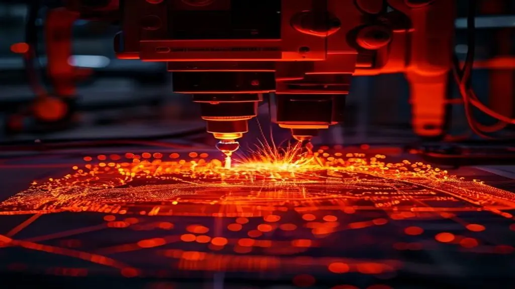
A thermal monitoring system deployed on a shipbuilding welding station continuously captures the infrared signature of the weld and its surrounding thermal field (see real-time thermal imaging of a live weld). For each weld pass, the system measures and records:
Preheat compliance. Before arc strike, the system confirms that the base metal temperature meets the minimum preheat requirement specified in the welding procedure. For DH36 plate above 30 mm, preheat minimums of 75–125°C are typical depending on the carbon equivalent and heat input range. The system flags any joint where preheat has dropped below threshold and creates an automatic non-conformance record if the arc is initiated in a non-compliant state.
Interpass temperature monitoring. On multi-pass joints—common in anything above 12 mm plate—interpass temperature must stay within the range specified in the weld procedure qualification. Too low and hydrogen diffusion risk increases; too high and the HAZ toughness degrades through grain growth. Continuous monitoring between passes closes the gap that spot-check pyrometry leaves open. Our preheat and interpass temperature monitoring guide covers the measurement methodology in detail.
Heat input tracking. The thermal spatial profile of the weld pool correlates with arc energy and travel speed. Deviations outside the qualified heat input range are identifiable from the thermal signature before the pass is complete. This is especially valuable on submerged arc welding (SAW) and FCAW stations where high deposition rates can push heat input toward the upper qualification limit during long horizontal seam runs.
Cooling rate and t₈/₅ estimation. The time from 800°C to 500°C (t₈/₅) determines whether the HAZ transforms to martensite, bainite, or a tougher microstructure. Thermal monitoring records the actual cooling curve at each joint location. For high-strength marine steels where HAZ toughness is the controlling fatigue performance parameter, this data is more informative than heat input alone.
Weld pool geometry. Asymmetry in the weld pool profile on fillet welds or irregular bead width on butt welds indicates arc instability, incorrect torch angle, or inconsistent travel speed. These deviations are precursors to lack-of-fusion and underfill defects that post-weld UT will later detect—but thermal monitoring flags them early, while the joint is still being made.
HeatCore in a shipyard production environment
HeatCore is Therness’s AI-powered real-time weld monitoring system, designed for integration into production welding stations. In a shipyard context, HeatCore operates as a continuous shipyard weld monitoring layer on FCAW, GMAW, and SAW stations welding hull structure, bulkheads, and tank boundaries.
The system’s AI engine analyses the thermal stream against the qualified welding procedure parameters, generating pass-level quality assessments in real time. Each assessed pass produces a timestamped record containing thermal profile data, compliance flags, and any non-conformance annotations. These records link automatically to the joint reference, the welder or robot ID, and the procedure specification—creating the joint-level documentation trail that ISO 3834-2 and classification society fabrication requirements demand.
For shops already using a welding data historian or MES integration, HeatCore feeds quality data directly into the production record. See our welding data historian and MES integration guide for architecture details.
HeatScan for field inspection and repair verification
Not all shipbuilding welds are made in a controlled station environment. Outfitting welds, structural repairs, and field modifications are performed in areas where fixed camera installations are impractical. HeatScan—Therness’s field thermography inspection system—covers these cases.
HeatScan is a portable active thermography system that allows inspectors to characterise weld quality and detect subsurface discontinuities in completed welds without ionising radiation. For repair welds on in-service vessels, this is particularly valuable: RT and PAUT require staging, radiation safety exclusion zones, and film development lead times that are incompatible with drydock schedules. HeatScan provides qualitative sub-surface information rapidly, allowing repair weld acceptance decisions to be made on the dock rather than waiting for laboratory results.
For a full overview of field thermography methodology, see our HeatScan field thermography inspection guide.
Digital traceability: meeting classification society documentation requirements
Classification societies perform periodic audits of welding quality systems and expect traceability from weld procedure specifications through to individual joint completion records. In practice this means:
- WPS and PQR records accessible per joint
- Welder or operator qualification certificates linked to the joints they performed
- Evidence that the welding conditions (preheat, interpass, heat input) were within the qualified procedure range for each joint
Manual systems—paper travellers, handwritten temperature logs, separate calibration records—create gaps and inconsistencies that auditors flag. When a classification surveyor requests evidence that Weld J-447 on Frame 83P was welded within the qualified procedure, a thermal monitoring record with timestamped temperature data and a direct link to the WPS/PQR is a significantly stronger response than a welder’s handwritten log entry.
the HeatCore QMS workflow, Therness’s welding quality management software, integrates with HeatCore monitoring data to maintain this traceability automatically. Weld records, qualification certificates, procedure documents, and non-conformance reports are stored in a single system with role-based access for quality engineers, welding coordinators, and auditors.
For guidance on the broader documentation framework under ISO 3834, see our ISO 3834 and EN 1090 traceability guide.
ROI: the cost of weld failures in shipbuilding
Shipbuilding is not a forgiving environment for weld defect discovery. A repair weld on an in-service vessel in drydock costs 20–40× the cost of the same repair performed during initial construction. Repair on a vessel in operation requires off-hire time, route disruption, and potentially delayed cargo commitments—costs that dwarf any inspection budget.
For yards pricing newbuild or repair work, the QuoteBuddy fabrication cost estimation guide breaks down how these risk multipliers enter a quote.
Weld defect cost analysis consistently shows that the economic break-even for continuous monitoring systems occurs when they prevent one or two significant repairs per year. In shipbuilding, where a single drydock visit for structural repair can run to hundreds of thousands of euros, the threshold for ROI is reached much faster than in most manufacturing contexts.
Beyond direct repair cost, in-process monitoring supports a reduction in post-weld NDT scope. Where continuous process monitoring demonstrates consistent procedure compliance, classification societies and ship owners increasingly accept a reduced UT sampling plan for low-risk joints. The monitoring record becomes an input to risk-based inspection decisions—reducing both NDT labour and the schedule pressure it creates during construction.
Bring real-time weld monitoring to your shipyard
HeatCore integrates into your existing welding stations to deliver continuous preheat, interpass, and heat input monitoring with automatic joint-level records—ready for classification society audits and ISO 3834 documentation requirements.
Request a HeatCore demoConclusion
Shipbuilding welding quality monitoring closes the gap between what post-weld NDT detects and what in-process thermal data can prevent. By capturing preheat compliance, interpass temperature, heat input, cooling rate, and weld pool geometry on every pass, a thermal monitoring system gives quality engineers and welding coordinators the earliest possible signal of process deviation—before defects are formed, before NDT is staged, and before a repair weld costs twenty times what a corrective action during production would have.
For shipyards building toward ISO 3834-2 certification, expanding their classification society approval scope, or simply reducing the cost and schedule impact of weld rework, thermal imaging is the foundational investment that makes all downstream quality evidence more credible and more defensible.
Contact Therness to arrange a HeatCore demonstration or discuss how HeatScan field inspection fits your drydock repair workflow — or browse the full HeatCore and HeatScan product range.
Therness solution: Welding camera — Thermal and high-speed imaging that watches the arc, the pool and the cooling seam while the weld is made.