A modern welding monitoring system promises something every fabrication shop wants: real-time evidence that each weld was made within its qualified process window, without waiting for radiographic or ultrasonic testing days later. The market answers that promise with three competing sensing modalities—thermal imaging, machine vision and acoustic emission—each with a different physics, defect coverage and total cost. This buyer’s guide lays out what each technology actually measures, where it fails, how it maps to ISO 3834 traceability requirements, and how to write an RFP that surfaces the right vendor for your weld mix.
What a welding monitoring system has to do
Before comparing technologies, fix the job to be done. A production-grade welding monitoring system needs to deliver four things, in this order:
- Detect process excursions in real time — heat input outside WPS bounds, lost shielding gas, arc instability, cooling-rate anomalies that drive HAZ embrittlement.
- Classify each joint as in-spec or suspect, with a per-joint pass/fail at the moment the arc extinguishes.
- Record traceability data — operator, WPS, consumable lot, joint ID, time-series of essential variables—into a queryable archive.
- Integrate with the MES, ERP or welding QMS so the quality decision flows downstream without manual transcription.
The three sensing modalities differ in how well they cover (1) and (2). Coverage of (3) and (4) is mostly a software question, and is where vendor differentiation actually lives once the physics question is settled.
Thermal imaging — direct measurement of the process
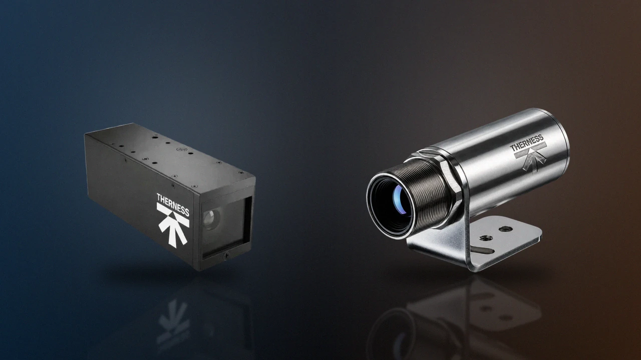
Thermal imaging cameras observe the weld pool, the surrounding heat-affected zone (HAZ) and the cooling track at frame rates from 30 Hz to several kHz. Modern infrared sensors give absolute temperature with ±2 K accuracy after pyrometric calibration, which is enough to compute heat input per pass and the t8/5 cooling time that governs microstructure. For a side-by-side of the hardware options, see our overview of weld monitoring cameras.
What it sees well:
- Heat input deviations (the root cause of most metallurgical defects)
- Lack of fusion driven by cold spots at joint root
- Excess heat input causing HAZ embrittlement, distortion, burn-through
- Interpass temperature compliance, validated against ISO 13916
- Cooling-rate anomalies that correlate with cracking risk
What it misses or struggles with:
- Surface geometry defects (undercut, reinforcement excess) without an additional profilometric channel
- Weld spatter occlusion of the molten pool view in some short-circuit GMAW regimes
- Reflective metals like polished aluminum, where emissivity correction is needed and mistakes are easy to make
Thermal imaging is the only modality that directly measures the physical mechanism behind ISO 5817 quality levels. Geometric inspection tells you the bead looks right; thermal monitoring tells you the metallurgy is right. Watch a thermal-AI monitoring system running on a live weld to see this in practice.
Machine vision — geometric truth, surface only
Visible-light or near-infrared machine vision uses high-frame-rate cameras (often paired with structured-light projectors or laser line profilometers) to reconstruct the bead geometry as it is laid down. This is the workhorse of robotic arc welding cells.
What it sees well:
- Bead width, height, leg length, throat thickness
- Undercut, overlap, misalignment, root gap variations
- Spatter density (a proxy for arc instability)
- Surface porosity once the bead is solidified
- Joint tracking for seam-following robotic welding
What it misses or struggles with:
- Subsurface defects entirely — vision is a 2D surface technique
- Lack of fusion not visible at the surface
- Cooling rate, heat input, HAZ effects
- Welds in restricted access where camera line-of-sight is occluded
- Smoke/spatter degradation of image quality without active filtering
Machine vision is the right answer when your defect taxonomy is dominated by surface and geometric non-conformities and your production economics demand fast throughput per cell. It is the wrong answer when your code (ASME Section VIII, EN 13445) demands evidence of internal soundness.
Acoustic emission — the niche specialist
Acoustic emission (AE) sensors detect elastic stress waves released by crack initiation, plastic deformation and phase transformation. In welding, AE has a long research history but a narrow commercial deployment.
What it sees well:
- Crack initiation in real time (especially solidification and hydrogen-induced cracks)
- Stress relief during PWHT
- Some inclusion-related phenomena
What it misses or struggles with:
- Most non-cracking defects (porosity, lack of fusion, geometric non-conformities)
- Background noise rejection in production environments — false positives from neighbouring cells, robots, fixtures
- Quantitative defect localization without dense sensor arrays
- Non-ferrous alloys where AE signatures are weaker
AE shines in specific high-consequence applications: pressure vessel longitudinal seams during PWHT, nuclear-grade welds, certain offshore wind tower circumferentials. As a primary monitoring modality for general fabrication, it is rarely the right technology choice on its own.
Decision matrix — pick the modality that matches your defect economy
| Driver | Thermal | Vision | Acoustic |
|---|---|---|---|
| Pressure vessel / Section IX shop | ✅ Primary | ⚠️ Complementary | ⚠️ PWHT only |
| Robotic arc welding cell | ✅ Primary | ✅ Primary | ❌ |
| Structural EN 1090 fabrication | ✅ Primary | ✅ Complementary | ❌ |
| Aerospace WAAM / DED | ✅ Primary | ✅ Complementary | ⚠️ Research |
| Aluminum reflective surfaces | ⚠️ Calibration-heavy | ✅ Primary | ❌ |
| Cracking-prone alloys (high-strength steel) | ✅ HAZ control | ❌ | ⚠️ Niche |
| Geometric defect dominated mix | ⚠️ Insufficient alone | ✅ Primary | ❌ |
| Heat-input-driven defect mix | ✅ Primary | ❌ | ❌ |
The honest reading: most production shops need thermal as the primary modality and vision as a complementary geometric layer. In the Therness lineup, the HeatCam IR-C fills that primary thermal role. Acoustic emission is a specialist tool for specific high-consequence applications, not a general-purpose answer.
Selection framework — a six-question screening
Use these six questions in order. Each one is a filter, not a scoring criterion.
1. What does your defect Pareto actually look like?
Pull the last 12 months of NCR data. Sort by defect type. If the top 80% is metallurgical (porosity, lack of fusion, HAZ cracking, hardness excursions), thermal wins. If the top 80% is geometric (undercut, reinforcement, misalignment), vision wins. If your data is too thin to know, you have a quality data problem before you have a monitoring problem—solve NCR management first.
2. What does your code demand?
ASME BPVC Section IX and EN 13445 ultimately want evidence of internal soundness. Vision alone will not satisfy a Notified Body audit on a Category III pressure vessel. EN 1090 execution class EXC2 is more permissive. Map the answer back to your code reference.
3. Robotic, mechanized, or manual?
Robotic cells favour vision because the camera position is deterministic and access is controlled. Manual welding favours thermal because the operator’s pose varies and only the heat field is observable consistently. Mechanized welding (orbital, longitudinal) tolerates either.
4. What integration depth do you need?
If the system has to feed the welding QMS, the MES and the ERP traceability records, the software stack matters more than the sensor — this is where a scoring layer like HeatCore AI, fusing the thermal and vision channels, earns its place. Ask vendors for their REST API spec, OPC-UA capabilities and historian compatibility before you sign.
5. Who owns calibration and how often?
Thermal sensors drift and require pyrometric recalibration. Vision systems need geometric and lighting calibration. Both can be automated, neither is free. A vendor that cannot tell you the field calibration interval and procedure is selling you a future operations problem.
6. What does total cost look like over five years?
Capex ranges from €25k for a single-channel thermal monitoring system to €250k+ for a multi-camera vision cell with reconstruction software. Opex is dominated by integration labour, calibration, and—often overlooked—the cost of false positives that pull joints into manual review. Build a five-year TCO that includes false-positive triage time at your loaded labour rate.
RFP shortcuts — what to demand from any vendor
A good welding monitoring system RFP covers technology, integration and operations. Specifically demand:
- Defect catalogue mapping — vendor must tell you which ISO 5817 imperfection classes their system detects, with sensitivity and specificity numbers from a referenced trial.
- Traceability schema — record fields, time-base, units, archive format. Minimum: heat input per pass, t8/5, interpass T, arc V/I time-series, joint metadata.
- API access — REST or OPC-UA, with read access to historical data and write access for joint-level WPS bindings.
- False-positive rate — measured on a representative sample of your weld types, not on lab specimens.
- Calibration plan — frequency, procedure, traceability to a national lab.
- Audit pack — sample reports for a typical ISO 3834 surveillance audit and an ASME Section IX vendor review.
If a vendor cannot answer all six in writing, they are selling capex without the operations contract you actually need.
Internal links worth following
- The HeatCore deep dive explains the thermal-AI architecture for in-process classification.
- Welding traceability with thermography covers the records side.
- The ROI calculator post gives a numerical frame for the business case.
- For the productized answer, see welding-monitoring-system and products.
Bottom line
The vendor question is downstream of the physics question. Pick the modality that matches your defect Pareto, your code obligations and your access constraints, then buy the integration depth that matches your QMS roadmap. For most shops covered by ISO 3834 and ASME Section IX, thermal monitoring is the primary modality and vision is the complementary geometric layer. Acoustic emission stays in its specialist box.
Want a scoped trial on your weld mix?
Therness runs a structured pilot on three of your representative joints and returns a defect-coverage matrix specific to your production. Real numbers, no marketing.
Book a scoped demoTherness solution: Welding monitoring system — Every weld inspected in the cycle, with defect flags and the ISO 3834 / ISO 17635 evidence kept per weld.
Frequently Asked Questions
Which welding monitoring technology has the highest defect sensitivity?
Thermal imaging is the only modality that directly measures the physical mechanism behind most metallurgical defects—heat input and cooling rate. Machine vision excels at geometric defects (undercut, misalignment) but is blind to subsurface and metallurgical issues. Acoustic emission is sensitive to cracking but produces high false-positive rates outside of well-characterized lab conditions.
Can a single welding monitoring system replace post-weld NDT?
No. In-process monitoring reduces the volume of welds that require post-weld NDT (UT, RT, PT) by flagging in real time the joints that left the acceptable process window, but ISO 3834 and code-driven NDT sampling rates still apply. The economic case is in catching defects within seconds instead of days, not in eliminating NDT.
How does a welding monitoring system fit into ISO 3834 and EN 1090 compliance?
ISO 3834 requires documented evidence that essential welding variables were maintained in production. A monitoring system that records heat input, interpass temperature and arc parameters per joint with operator and WPS metadata satisfies the traceability requirement of ISO 3834-2 §14 and provides the production records expected by EN 1090-2 audits.