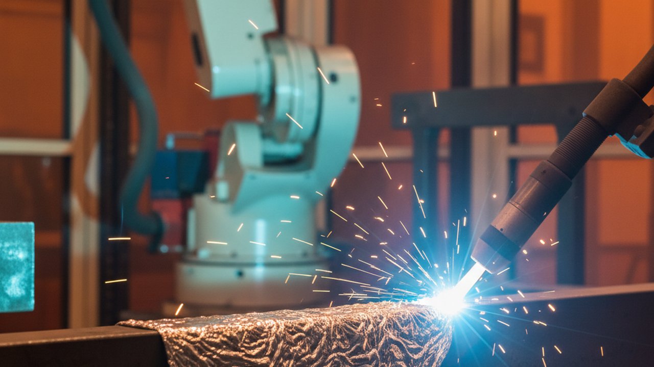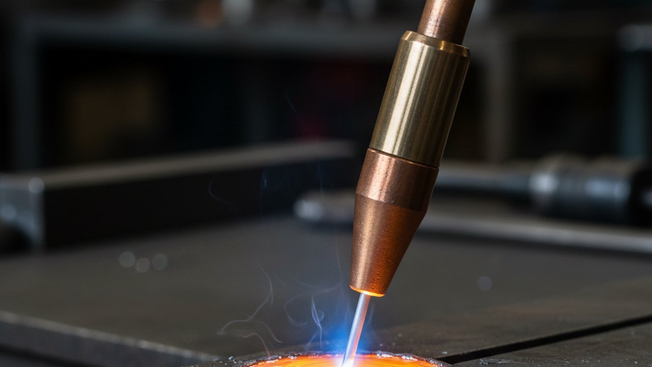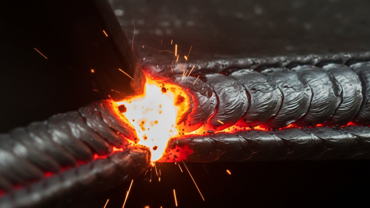
Watch a weld pool on high-speed video and most of the useful information sits at its trailing edge, not its leading one. The front is where the arc melts new material; the back is where that metal gives the heat up again and locks into a permanent microstructure. Reading how fast that trailing edge advances, and what shape it holds while doing it, turns a clip of glowing metal into three readouts: the ripple record on the bead, an estimate of local cooling rate, and an early flag for centreline hot-crack risk. This article is a companion to Therness’s CMT weld pool footage at 480 fps and works through what to look for at that boundary, frame by frame.
Key takeaways
- The trailing edge is the freeze front: the moving boundary between liquid metal and solid bead, with a narrow mushy zone in between.
- Ripples on a finished bead are a frame-by-frame record of the front pausing and advancing as the process pulses heat in and lets it drain away.
- Trailing-edge speed, measured against a fixed reference in the frame, is a fast visual proxy for local cooling rate — not a substitute for a measured t8/5.
- A teardrop-shaped trailing edge closing to a sharp centreline cusp is a known risk pattern for solidification (hot) cracking.
- Standard 30–60 fps shows that ripples formed but blurs the pause-and-advance motion inside each cycle; reading that motion needs a camera in the low hundreds of frames per second.
- None of this replaces classification or acceptance testing — it flags where to look closer, and when to reach for thermography or NDT.
What the trailing edge of the pool actually shows
A weld pool is not a liquid blob with a hard edge. It is a small volume of fully molten metal at the front, under and just behind the arc, that thins into a mushy zone — part liquid, part solid — before finishing the transition to solid bead. Ordinary video blurs that transition into the boundary of a bright shape; footage in the low hundreds of frames per second shows the mushy zone as a distinct band, and the trailing edge is the line where it closes.
That line is where the finished joint’s solidification structure gets decided. How fast it sweeps forward sets how long any point spends in the mushy zone as grain structure forms — a pace that correlates with, but is not the same interval as, the later cooling time t8/5 figure, which tracks austenite decomposition from 800 to 500 °C after the metal has already gone solid. Watching the weld pool trailing edge on video is watching the earlier half of the same thermal history.

Ripple formation: a frame-by-frame record of the freeze front
The regular ripples on almost any finished weld bead are not decoration. Each marks one cycle of the trailing edge slowing, holding, and advancing again — on the footage above, tied directly to CMT’s interval parameter pulsing heat into the pool and letting it drain away between pulses. Slowed down, a stretch of bead that looks like fixed texture resolves into a countable sequence: one ripple per pulse, each a small fossil of the moment the front paused before pushing on.
That makes ripple spacing readable after the weld has cooled, without the camera running at all — but reading it while the pass is still in progress turns it into a control signal rather than an inspection curiosity. Even, regular ripples say the front kept pace with the torch and the interval settings stayed matched to the joint. A pattern that widens, narrows unevenly, or breaks rhythm says the front fell behind or surged ahead of where the process expected it, worth checking against travel speed and interval settings before it becomes a defect.
Measuring trailing-edge speed, and what it says about cooling rate
Trailing-edge speed is straightforward to estimate frame by frame, with one governing assumption: in a steady pass the front tracks the torch at travel speed, so an estimate is really a measurement of deviation from that baseline. Pick a fixed reference length in the frame — stick-out, a scale in the enclosure, or travel speed times frame interval — and count how many frames the front takes to cross it. Comparing cycle to cycle beats a mean across the clip, and any figure carried further should note its assumptions: lighting, arc-glare filtering, and where the analyst calls the mushy-zone edge all shift the count.
The speed matters because of its relationship to cooling rate. A faster front, at the same heat input, spends less time carrying a point through the mushy zone, correlating with a shorter local cooling time overall — a separate, later interval that a defensible t8/5 measurement quantifies from thermal data once the metal has already solidified. If the front visibly speeds up mid-pass with no parameter change, something shifted the local heat balance — a fixture heat sink, a thickness change, accumulated interpass heat — worth checking with a t8/5 calculation before qualifying the result. It is not a replacement for that calculation: video gives direction, a procedure record needs a number with a stated method behind it.
Reading hot-crack risk in the same footage
The trailing edge carries a second signal beyond speed: its shape. As the pool solidifies, grains grow inward from both sides toward the centreline. On a pool that stays compact and rounded, those fronts meet at a shallow angle and the last liquid between them can still be fed by metal flowing in behind it. On a pool that elongates into a teardrop — often from high travel speed relative to heat input — the same fronts meet almost head-on at a sharp trailing cusp, trapping the last, most segregated liquid with the least material around it to resist the shrinkage strain as it cools. That geometry is a long-established risk pattern for centreline solidification cracking, visible on high-speed footage well before any crack could be confirmed.
This is a risk indicator to watch for on camera, not a substitute for classification or acceptance testing. ISO 6520-1 files a crack running along the weld axis under reference 101; the 101 — longitudinal (centreline) crack reference card notes it is most often a solidification crack. Acceptance for any crack found stays with the applicable product standard, not with what the footage suggests.
A pool that narrows and elongates as travel speed increases, or the joint thins, is worth following through several cycles rather than one frame — a momentary elongation is not a sustained shift.
Failure modes and what to check
- Ordinary video frame rates. Thirty or sixty fps shows that ripples formed but smears the pause-and-advance motion inside each cycle. Fix: use a camera fast enough to resolve that motion for your process.
- Reading absolute speed instead of deviation from travel speed. A steady-state front already moves at travel speed; a stable reading is not a discovery. Fix: baseline against programmed travel speed.
- A single frame read as the finding. Ripple spacing and pool elongation are cyclical. Fix: follow the pattern across several cycles, and route anything needing a defensible figure to thermography, calculation, or NDT rather than the video estimate.
Step-by-step: setting up your own trailing-edge review
- Confirm your camera resolves your process’s cycle for your material and thickness.
- Establish a fixed reference in the frame — stick-out, a placed scale, or travel speed times frame interval.
- Film a steady, in-specification pass first to set a baseline ripple spacing and trailing-edge speed.
- Step through cycle by cycle, marking where the front speeds up, slows, or the pool elongates toward a cusp, then cross-check any sustained change against travel speed, heat input, and interpass condition before routing it to thermography, calculation, or NDT.
Standards for classification and acceptance
This article deliberately does not restate crack acceptance limits or quality-level tables — those live in the standards. ISO 6520-1 is the classification vocabulary, assigning the centreline crack family its own reference number, covered on this site’s ISO 6520-1 reference card. ISO 5817 sets quality levels for fusion-welded steel, nickel, titanium and their alloys, indexed by those numbers — see the causes and prevention guide to hot and cold cracking for how the two fit together. TWI Job Knowledge covers solidification cracking mechanisms further.
From reading footage to catching it live
Reading a clip after the weld has cooled is a training exercise. Catching the same signal while the pass is running is what an in-process camera is for. PoolDrop films the pool torch-side at up to 480 fps, with arc-glare suppression that keeps the trailing edge readable — the view behind the footage above. See the welding camera overview for the case for filming the process, the CMT weld pool solidification video page this accompanies, and why weld bead ripples form during solidification for the ripple physics itself.
FAQ
What does the trailing edge of the weld pool actually show on high-speed video? The freeze front: where liquid metal finishes crossing a narrow mushy zone and becomes solid bead — the single most information-dense part of the pool to watch frame by frame.
How do ripples on a finished weld bead relate to what happened in the pool? Each ripple records one cycle of the freeze front pausing and advancing as the process pulses heat in and lets it drain away. On CMT, where the interval parameter paces that pulse directly, ripple spacing is a readable trace of it.
How is trailing-edge speed measured from frame-by-frame footage? Pick a fixed reference length in the frame — stick-out, a scale in the enclosure, or travel speed times frame interval — and count frames as the front crosses it. Frame-to-frame drift from the travel-speed baseline usually matters more than the absolute number.
What does a faster or slower trailing-edge advance indicate about cooling rate? Directionally, a front advancing faster at the same heat input spends less time in the mushy zone, correlating with a shorter local cooling time. It is a fast visual proxy, not a replacement for a defensible t8/5 figure — a reason to check the number, not the number itself.
Can trailing-edge geometry on video indicate hot-crack risk? Yes, as an indicator worth a closer look. An elongated, teardrop-shaped pool pushes columnar grains toward the centreline, and a sharp trailing cusp where they meet is a known risk pattern for centreline solidification cracking. It flags where to inspect, not a verdict on its own.
What frame rate is needed to read the trailing edge usefully? Standard 30 or 60 fps shows that ripples formed but blurs the pause-and-advance motion inside each cycle into a smear, showing that the bead solidified but not how the front moved. A camera in the low hundreds of frames per second resolves that pause-and-advance motion within each cycle.
Is ripple spacing a substitute for measuring t8/5 cooling time directly? No. Ripple spacing and trailing-edge speed are a fast, camera-only read on every pass. t8/5 is the standardised interval — 800 to 500 degrees Celsius — measured or calculated for procedure qualification, and video is not an accepted substitute.
Does this reading method apply to processes other than CMT? Yes. Any process leaving a liquid pool behind a moving heat source — GMAW, GTAW, PAW, laser and hybrid welding, WAAM deposition — has a trailing edge and a ripple record to read. CMT is simply a clean case because its interval parameter paces the cycle directly.
See the trailing edge while the pass is still running
PoolDrop films the weld pool at up to 480 fps with arc-glare suppression, so the freeze front is readable in real time instead of only after the bead has cooled.
Talk to an engineerTherness solution: Welding camera — Thermal and high-speed imaging that watches the arc, the pool and the cooling seam while the weld is made.
Frequently Asked Questions
What does the trailing edge of the weld pool actually show on high-speed video?
The freeze front: where liquid metal finishes crossing a narrow mushy zone and becomes solid bead — the single most information-dense part of the pool to watch frame by frame.
How do ripples on a finished weld bead relate to what happened in the pool?
Each ripple records one cycle of the freeze front pausing and advancing as the process pulses heat in and lets it drain away. On CMT, where the interval parameter paces that pulse directly, ripple spacing is a readable trace of it.
How is trailing-edge speed measured from frame-by-frame footage?
Pick a fixed reference length in the frame — stick-out, a scale in the enclosure, or travel speed times frame interval — and count frames as the front crosses it. Frame-to-frame drift from the travel-speed baseline usually matters more than the absolute number.
What does a faster or slower trailing-edge advance indicate about cooling rate?
Directionally, a front advancing faster at the same heat input spends less time in the mushy zone, correlating with a shorter local cooling time. It is a fast visual proxy, not a replacement for a defensible t8/5 figure — a reason to check the number, not the number itself.
Can trailing-edge geometry on video indicate hot-crack risk?
Yes, as an indicator worth a closer look. An elongated, teardrop-shaped pool pushes columnar grains toward the centreline, and a sharp trailing cusp where they meet is a known risk pattern for centreline solidification cracking. It flags where to inspect, not a verdict on its own.
What frame rate is needed to read the trailing edge usefully?
Standard 30 or 60 fps shows that ripples formed but blurs the pause-and-advance motion inside each cycle into a smear, showing that the bead solidified but not how the front moved. A camera in the low hundreds of frames per second resolves that pause-and-advance motion within each cycle.
Is ripple spacing a substitute for measuring t8/5 cooling time directly?
No. Ripple spacing and trailing-edge speed are a fast, camera-only read on every pass. t8/5 is the standardised interval — 800 to 500 degrees Celsius — measured or calculated for procedure qualification, and video is not an accepted substitute.
Does this reading method apply to processes other than CMT?
Yes. Any process leaving a liquid pool behind a moving heat source — GMAW, GTAW, PAW, laser and hybrid welding, WAAM deposition — has a trailing edge and a ripple record to read. CMT is simply a clean case because its interval parameter paces the cycle directly.