Weld pool visualization means two different things depending on who is asking for it. A welding engineer troubleshooting a defect wants to see the pool — a camera image showing oscillation, spatter, or a collapsed bead. A plant manager scaling a robotic cell wants a decision — pass or fail, joint by joint, without a human watching every weld. The first need is served by a camera; the second is served by software. Buying the wrong one, or assuming one replaces the other, is the most common mistake in weld-monitoring procurement. This guide compares both approaches directly: what each actually shows, where each fails, how to combine them, and how to validate whichever setup you choose before it goes into production.
Key Takeaways
- Weld pool visualization splits into two distinct capabilities — direct camera-based viewing and software-derived analysis — and most production systems need both, not one instead of the other.
- A weld pool camera provides optical evidence a human can review; weld pool visualization software converts sensor data (camera, thermal, or arc signal) into an automated pass/fail decision at production speed.
- Frame rate is the single spec that separates a usable weld pool camera from a demonstration: 240 to 480 fps resolves the pool oscillation and transient events that most correlate with defects; 30 to 60 fps averages them away.
- Software-only approaches that infer pool state from arc voltage/current can flag anomalies without a camera, but they cannot produce the optical record required for ISO 17637 visual testing.
- The most common failure mode is treating camera footage as if it were an automated inspection system, or treating software output as if it needed no visual corroboration — both create audit gaps.
- Timestamped, weld-ID-tagged visualization data (camera or software-derived) is acceptable ISO 3834-2 process monitoring evidence, provided it is validated against the qualified procedure window.
- Combining a camera for evidence with software for real-time decisions is the configuration that scales past a handful of joints per shift without adding inspection headcount.
Table of Contents
- What Weld Pool Visualization Means: Camera View vs Software-Derived Insight
- Camera-Based Weld Pool Visualization: What a Direct View Actually Shows
- Software-Based Weld Pool Visualization: AI Inference and Automated Grading
- Decision Framework: Camera, Software, or Both
- Common Failure Modes and How to Fix Them
- Validating and Documenting Weld Pool Visualization for Audit
- Step-by-Step Implementation Procedure
- Frequently Asked Questions
What Weld Pool Visualization Means: Camera View vs Software-Derived Insight
The molten weld pool carries more diagnostic information than any other part of the welding process — its oscillation frequency correlates with penetration depth, its surface behaviour flags incipient porosity, and its solidification pattern predicts hot-cracking risk. Getting at that information is where the two branches of weld pool visualization diverge.
Camera-based visualization produces a direct optical image: arc glare is filtered with narrow-bandpass optics or matched illumination, and the sensor captures the pool’s actual geometry, motion, and surface behaviour at a high enough frame rate to resolve transient events. The output is a video record a person can review, frame by frame if needed.
Software-based visualization does not necessarily require an optical image at all. It can reconstruct pool state indirectly from arc voltage and current waveforms, from a thermal imaging stream, or from a lower-resolution vision feed, and it applies a trained model or rule set to classify what it infers — oscillation frequency drop, spatter cluster, asymmetric solidification — into an alarm, a grade, or a logged parameter. A recent ScienceDirect review of vision sensing technologies in robotic welding surveys exactly this landscape: dozens of sensing and inference approaches, none universally superior, each suited to a different combination of process, defect type, and production speed.
The practical distinction that matters for procurement: a camera answers “what did the pool do here?” for one weld, on demand. Software answers “was this weld within spec?” for every weld, automatically. Confusing the two — buying a camera and expecting automated grading, or buying grading software and expecting an audit-ready visual record — is the single most common procurement mistake in this space.
Neither approach is a full substitute for the welding camera category as a whole. Thermal imaging, high-speed visual cameras, and acoustic sensing all feed weld pool visualization pipelines differently — this guide focuses specifically on the camera-vs-software decision, not on choosing between sensing physics.
Camera-Based Weld Pool Visualization: What a Direct View Actually Shows
A dedicated weld pool camera exists to solve one problem: standard industrial cameras at 30 to 60 fps see a saturated bright blob where the pool actually is, because arc emission overwhelms the sensor and the frame rate is too slow to resolve the pool’s real motion. A purpose-built weld pool camera pairs a high frame rate — typically 240 to 480 fps — with either a narrow-bandpass filter matched to an illumination wavelength, or laser-safe active lighting tuned to suppress arc glare while revealing the pool surface.
At that frame rate, three events become directly observable that a slower camera averages away:
- Pool oscillation. In GMAW, the pool typically oscillates at 40 to 80 Hz; resolving the cycle requires sampling well above that frequency, which is why 480 fps — not 60 fps — is the practical minimum for penetration-related analysis.
- Spatter origin. High-speed capture shows where spatter droplets initiate on the pool surface, not just that spatter occurred, which is the difference between a symptom and a root cause.
- Solidification front behaviour. The trailing edge of the pool, where the metal actually freezes, is where asymmetric cooling and hot-cracking precursors show up first — and it is only visible at high frame rate with adequate exposure control.
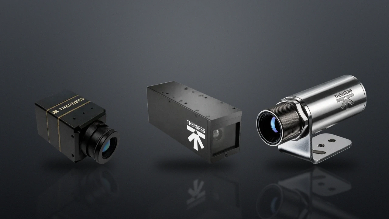
Therness PoolDrop is a purpose-built weld pool camera in this category, capturing up to 480 fps with integrated Class 1 laser-safe illumination (IEC 60825-1) and plugging into a HeatCore server over USB 3.0. For a full technical breakdown of frame rate, exposure, and arc-suppression specifications, see the dedicated 480 fps weld pool camera guide.
A camera alone does not make a decision. Recorded footage is audit-grade evidence and an excellent root-cause tool, but a human — or a downstream software layer — still has to interpret it. Camera-only deployments are common and legitimate for procedure development and evidence retention; they are not automated inspection systems on their own.
Camera-based visualization also has a direct compliance role: recorded footage, timestamped and tagged to the joint ID, can partially satisfy ISO 17637 visual testing documentation requirements when field of view, working distance, and resolution are defined in the inspection plan and validated against the standard’s acceptance criteria.
Software-Based Weld Pool Visualization: AI Inference and Automated Grading
Software-based weld pool visualization is the decision layer that most quality managers are actually procuring when they say “we need real-time weld monitoring.” It ingests sensor data — from a weld pool camera, a thermal imaging stream, or arc electrical signals — and outputs something a production line can act on: a pass/fail gate, a defect classification, a trend chart, or a documentation record.
Three architectures are in production use today:
- Rule-based thresholding. Fixed limits on measured parameters (peak temperature, oscillation frequency band, arc voltage range) trigger an alarm when breached. Simple to validate, but brittle across geometry and material changes.
- Trained classification models. AI models trained on labelled defect images or signal patterns classify new welds against learned categories. These generalise better across process variation but require a representative training set and periodic recalibration as consumables and fixtures age.
- Hybrid systems. Rule-based gates for hard safety/compliance limits, combined with a trained model for softer defect classification — the configuration used by most mature production deployments, because it keeps the auditable logic simple while still catching pattern-based defects.
For a full evaluation framework — integration architecture, validation protocol, and vendor-selection checklist — see the companion weld defect detection software buyer’s guide. Therness’s own software layer, HeatCore AI, runs this hybrid architecture on top of HeatCam thermal streams and PoolDrop visual streams from the same server, so a single weld record carries both the raw sensor evidence and the software’s classification of it.
A trained model is only as good as its validation. AI weld pool classification that has not been checked against an independent inspection reference on a statistically meaningful sample is a demo, not a production system — see the validation section below before trusting any vendor’s accuracy claim.
Software-based systems increasingly extend toward closed-loop control rather than passive monitoring: a digital twin architecture continuously compares live sensor readings against a modelled expected state and can feed corrections back to the robot controller in real time, rather than only flagging a completed weld after the fact. That capability depends entirely on the software layer — a camera by itself has no feedback path to the controller.
Decision Framework: Camera, Software, or Both
Use the table below to match the visualization approach to the actual production question you are trying to answer. Most cells that say “camera + software” reflect the majority of real production deployments — pure camera-only or pure software-only systems are legitimate but narrower use cases.
| Production question | Recommended approach | Why |
|---|---|---|
| ”What actually happened on this rejected weld?” | Camera | Root-cause review needs a direct optical record, not a classification score |
| ”Is every weld on this robotic line within spec, unattended?” | Software (camera-fed or thermal-fed) | Automated pass/fail at production speed is a software function, not a viewing function |
| ”Can I show an auditor objective process monitoring evidence?” | Camera + software | Raw footage plus a logged classification together satisfy both visual and quantitative documentation expectations |
| ”I need to qualify a new WPS and understand pool behaviour” | Camera | Procedure development is a human-interpretation task; automated grading comes after the window is established |
| ”I need to cut inspection headcount on a high-volume cell” | Software | Only automated classification scales past what a human inspector can watch continuously |
| ”I want closed-loop control that adjusts parameters mid-weld” | Software (with camera or thermal feed) | Feedback to the robot/PLC requires the software decision layer; a camera has no control path |
If you can only fund one system this budget cycle: for procedure qualification and root-cause capability, start with a camera. For production-scale automated gating across many joints per shift, start with software fed by whatever sensor (camera, thermal, or both) best matches your dominant defect mode. Combine them as the second phase — most fabricators land there within a year regardless of which they buy first.
Common Failure Modes and How to Fix Them
| Failure mode | Root cause | Fix |
|---|---|---|
| Camera footage collected but never reviewed | No defined review workflow or storage/retrieval process; footage becomes “just in case” data nobody uses | Define a review trigger (e.g., every rejected weld, or a sampling rate) and a retrieval path tied to weld ID before deployment, not after |
| Software alarms with no visual corroboration | Automated classification trusted without an evidence trail behind it | Pair the software gate with a camera or thermal stream retained per weld so a flagged joint can be reviewed, not just logged as “fail” |
| Model accuracy degrades over weeks | Training data mismatch as consumables wear, fixture position drifts, or material grade changes | Schedule periodic recalibration against a fresh reference sample set, the same way a physical instrument is recalibrated |
| False confidence from a single-point sensor feeding software | Arc-signal-only inference misses pool-surface events (spatter origin, solidification asymmetry) that only an optical view resolves | Add a camera feed for defect modes with a visible-but-not-electrically-detectable signature before expanding software scope to cover them |
| Frame rate too low for the claimed capability | 30 to 60 fps camera marketed as suitable for oscillation or penetration analysis | Verify against the frame-rate table in the 480 fps weld pool camera guide before specifying hardware; match frame rate to the transient event duration, not a round number |
| Arc glare not adequately suppressed | Generic industrial camera without matched illumination or bandpass filtering | Specify laser-safe matched illumination and a bandpass filter rated for the specific welding process’s arc spectrum, not a general-purpose machine vision lens |
Validating and Documenting Weld Pool Visualization for Audit
An ISO 3834-2 surveillance visit, or an internal quality audit, asks the same question regardless of whether the visualization is camera-based, software-based, or both: can you prove the qualified process window was actually maintained on the parts you shipped, not just documented as a target?
For camera-based evidence, that means:
- Field of view, working distance, and resolution documented in the inspection plan and validated against ISO 17637 visual testing requirements where the footage is used in place of, or alongside, manual visual inspection.
- Footage retained and retrievable by weld ID, with retention duration matching the applicable code or customer contract requirement.
- Inspector qualification under ISO 9712 documented for anyone making an accept/reject call from reviewed footage, the same as for direct visual inspection.
For software-derived evidence, add:
- A validation record comparing software output against independent inspection results on a representative sample — TWI Global’s guidance on in-process weld monitoring recommends defining acceptance criteria at commissioning and re-verifying after any maintenance event, not assuming vendor bench figures carry over to your process.
- A recalibration schedule and log, treated with the same rigor as a physical instrument’s calibration program, per general NIST manufacturing measurement guidance.
- Traceability from each software classification back to the raw sensor data it was derived from, so a disputed result can be re-reviewed rather than taken on faith.
A pass/fail log with no underlying sensor record behind it is not equivalent to weld pool visualization for audit purposes — the classification is only as defensible as the evidence it was derived from.
Step-by-Step Implementation Procedure
- Define the question you need answered first. Root-cause capability for procedure development points toward camera; unattended production-speed gating points toward software. Most programs need both eventually — decide which comes first based on your nearest deadline.
- Select sensing hardware matched to your dominant defect mode. Surface and geometry defects favour a high-speed visual weld pool camera; subsurface thermal anomalies favour thermal imaging; combine both where budget allows on a shared server platform.
- Specify frame rate and illumination against the actual transient events you need to resolve, not a generic spec sheet number — use the frame-rate-to-event mapping in the 480 fps weld pool camera guide as a starting reference.
- If deploying automated grading, scope the software integration before hardware procurement. Robot/PLC signal integration (OPC-UA or Modbus), weld ID input, and ERP export for non-conformance traceability are deployment milestones that shape total project cost more than the sensor itself.
- Run a parallel validation phase. For a defined period, let the software judge in real time while certified visual inspectors independently classify the same welds, then compare results across at least 200 welds before trusting the system unsupervised.
- Document the retention and review workflow before go-live, not after the first customer audit asks for it — define who reviews flagged welds, how footage is retrieved by weld ID, and how long records are kept.
- Re-validate after any process change. A change in wire, shielding gas, fixture, or joint geometry invalidates the previous validation; treat it as a new commissioning event for both the camera field of view and the software’s classification thresholds.
Frequently Asked Questions
What is weld pool visualization?
Weld pool visualization is the general term for any method that makes the molten weld pool observable during welding — either directly, through a camera that filters arc glare and captures the pool optically, or indirectly, through software that reconstructs pool state from sensor data such as thermal images, arc voltage/current, or acoustic signals.
What is the difference between a weld pool camera and weld pool visualization software?
A weld pool camera is hardware that produces a direct optical image of the molten pool for a human or a downstream algorithm to interpret. Weld pool visualization software is the analysis layer that turns raw sensor output — from a camera, thermal sensor, or arc monitor — into a classification, alarm, or quality record. Most production systems use both: a camera or thermal sensor to capture, and software to decide.
Can weld pool visualization software replace a camera?
Not for direct visual evidence. Software can infer pool state indirectly from arc electrical signals or thermal data without a camera, but it cannot produce the optical record needed for visual testing under ISO 17637 or for a human reviewer to confirm what actually happened at the pool. Camera and software are complementary, not substitutes for each other.
What frame rate do I need for real-time weld pool visualization?
For pool oscillation and penetration-related analysis, target a minimum of 240 to 480 frames per second — standard 30 to 60 fps industrial cameras average away the transient events that most correlate with defects. Slower, stable manual TIG can tolerate 120 to 240 fps; droplet-transfer detail in pulsed GMAW benefits from 1000 fps or more.
Does weld pool visualization satisfy ISO 3834 process monitoring requirements?
Timestamped, weld-ID-tagged visualization data — whether from a camera or software-derived analysis — can serve as objective process monitoring evidence under ISO 3834-2 clause 7.4, provided it is validated against the qualified procedure window and retained as part of the weld record. The standard requires demonstrable monitoring; it does not mandate a specific sensing modality.
Is camera-based or software-based weld pool visualization better for a robotic welding cell?
Neither is categorically better — they answer different questions. A camera gives direct visual evidence for audit and root-cause review. Software gives automated pass/fail decisions at production speed, which a human cannot do joint by joint across a full shift. Robotic cells running high volumes typically need software for the real-time gate and camera footage for the evidence trail behind it.
How much does adding weld pool visualization to an existing robotic welding cell typically cost?
Camera-only visualization (capture and recording, no automated decision-making) is the lower-cost entry point and integrates over USB with minimal PLC work. Software-driven automated grading requires an integration layer to the robot/PLC and a validation phase against reference inspection data, which is the larger share of total project cost, not the sensor hardware itself.
Further reading: American Welding Society (AWS) standards resources, ASME’s welding and quality codes hub, TWI Global’s technical knowledge base on in-process weld monitoring, a peer-reviewed review of vision sensing technologies in robotic welding, and a machine-vision study on in-process lack-of-fusion detection published via the National Institutes of Health.
Related on Therness: visualization vs thermographic AI camera comparison and HeatCore weld monitoring system overview.
See Camera and Software-Driven Weld Pool Visualization Together
Therness PoolDrop captures the weld pool at up to 480 fps; HeatCore AI turns that stream, alongside thermal data, into automated pass/fail decisions. Talk to an engineer about which configuration fits your line.
Talk to an EngineerTherness solution: Welding camera — Thermal and high-speed imaging that watches the arc, the pool and the cooling seam while the weld is made.
Frequently Asked Questions
What is weld pool visualization?
Weld pool visualization is the general term for any method that makes the molten weld pool observable during welding — either directly, through a camera that filters arc glare and captures the pool optically, or indirectly, through software that reconstructs pool state from sensor data such as thermal images, arc voltage/current, or acoustic signals.
What is the difference between a weld pool camera and weld pool visualization software?
A weld pool camera is hardware that produces a direct optical image of the molten pool for a human or a downstream algorithm to interpret. Weld pool visualization software is the analysis layer that turns raw sensor output — from a camera, thermal sensor, or arc monitor — into a classification, alarm, or quality record. Most production systems use both: a camera or thermal sensor to capture, and software to decide.
Can weld pool visualization software replace a camera?
Not for direct visual evidence. Software can infer pool state indirectly from arc electrical signals or thermal data without a camera, but it cannot produce the optical record needed for visual testing under ISO 17637 or for a human reviewer to confirm what actually happened at the pool. Camera and software are complementary, not substitutes for each other.
What frame rate do I need for real-time weld pool visualization?
For pool oscillation and penetration-related analysis, target a minimum of 240 to 480 frames per second — standard 30 to 60 fps industrial cameras average away the transient events that most correlate with defects. Slower, stable manual TIG can tolerate 120 to 240 fps; droplet-transfer detail in pulsed GMAW benefits from 1000 fps or more.
Does weld pool visualization satisfy ISO 3834 process monitoring requirements?
Timestamped, weld-ID-tagged visualization data — whether from a camera or software-derived analysis — can serve as objective process monitoring evidence under ISO 3834-2 clause 7.4, provided it is validated against the qualified procedure window and retained as part of the weld record. The standard requires demonstrable monitoring; it does not mandate a specific sensing modality.
Is camera-based or software-based weld pool visualization better for a robotic welding cell?
Neither is categorically better — they answer different questions. A camera gives direct visual evidence for audit and root-cause review. Software gives automated pass/fail decisions at production speed, which a human cannot do joint by joint across a full shift. Robotic cells running high volumes typically need software for the real-time gate and camera footage for the evidence trail behind it.
How much does adding weld pool visualization to an existing robotic welding cell typically cost?
Camera-only visualization (capture and recording, no automated decision-making) is the lower-cost entry point and integrates over USB with minimal PLC work. Software-driven automated grading requires an integration layer to the robot/PLC and a validation phase against reference inspection data, which is the larger share of total project cost, not the sensor hardware itself.