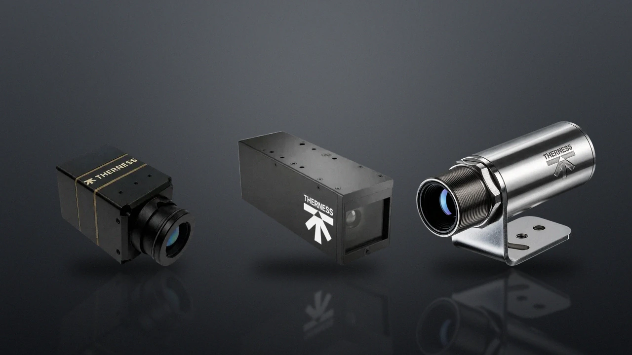
A weld pool camera running at 480 fps turns the molten pool from an inscrutable bright blob into a measurable diagnostic signal. Standard frame-rate cameras — 25 to 60 fps — capture only averaged weld pool states. They will tell you whether a pool existed, but they miss the transient events that cause most defects: pool collapse under insufficient heat input, arc instability during short-circuit transfer, and solidification cracks forming within milliseconds at the trailing pool edge.
At 480 fps, each frame captures a 2 ms slice of the process. Pool oscillation — a direct proxy for penetration depth — becomes measurable. Spatter ejection trajectories appear from initiation to flight. Solidification front progression in the final milliseconds of pool freeze can be correlated directly with the porosity and lack-of-fusion mechanisms flagged in ISO 5817 imperfection classifications. This is the core promise of real-time weld pool visualisation: defects become predictable while the weld is still being made.
This guide covers what high-speed weld pool cameras observe, how frame rate and arc-light suppression interact, the specifications that separate a usable system from an expensive demonstration, the common failure modes seen in the field, and a step-by-step procedure to validate a 480 fps installation before it goes into production. For broader context on selecting any welding camera, this guide focuses specifically on the high-speed visual modality.
Key Takeaways
- A 480 fps weld pool camera samples every 2 ms, resolving the full 40 to 80 Hz GMAW pool oscillation cycle that lower frame rates average away.
- The three highest-value observable events are pool oscillation frequency (penetration proxy), spatter ejection origin (porosity precursor), and trailing-edge solidification asymmetry (hot-cracking precursor).
- Frame rate alone is not enough: to freeze pool motion at 480 fps the exposure must be 200 to 500 microseconds, which demands either a high-sensitivity sensor or wavelength-matched active illumination.
- Arc-light suppression is mandatory — a narrow bandpass filter (±10 nm) matched to a monochromatic illumination source blocks broadband arc emission while passing the reflected pool image.
- Match the frame rate to the event: 480 fps for oscillation and penetration, 240 fps for spatter origin, 1000 fps or more for droplet detachment in pulsed GMAW.
- Timestamped, seam-synced pool data is a valid electronic process record under ISO 3834-2 clause 7.4 and is increasingly used for EN 15085 CP A1/A2 continuous monitoring.
- The most common field failures are optical window contamination, illumination drift, and unsynchronised acquisition during pulsed processes — each has a defined corrective action.
Table of Contents
- What 480 fps Reveals That Standard Cameras Miss
- Core Camera Specifications for Weld Pool Imaging
- Integration With Quality Standards
- Weld Pool Camera vs Thermal Camera
- Process-Specific Considerations
- Common Failure Modes and Fixes
- Installation and Validation Procedure
- FAQ
What 480 fps Reveals That Standard Cameras Miss
The weld pool oscillates. In a GMAW (MIG/MAG) process with standard 1 m/s wire feed, the pool oscillates at 40 to 80 Hz depending on current waveform and joint geometry. A 30 fps camera samples this at one frame every 33 ms — it cannot distinguish a stable pool from one at the edge of collapse. A 480 fps weld pool camera samples every 2 ms, resolving the full oscillation cycle and making the pool’s dynamic behaviour directly observable. The physics of arc emission that make this difficult — and the filtering that makes it possible — are introduced in Gas metal arc welding fundamentals and applied through machine vision sensing.

Measurable events by frame rate
| Frame rate | Observable weld pool events |
|---|---|
| 25–60 fps | Average geometry, gross arc faults, obvious arc interruptions |
| 120–240 fps | Short-circuit transfer cycles, spatter ejection (visible after launch) |
| 480+ fps | Pool oscillation frequency, solidification front, spatter origin sites |
| 1000+ fps | Droplet detachment detail, arc re-ignition events in pulsed GMAW |
The Nyquist sampling principle sets the floor: to characterise a periodic event you must sample at more than twice its frequency. A pool oscillating at 80 Hz therefore requires at least 160 effective samples per second simply to detect the frequency, and several times that to characterise the waveform shape. Because welding is rarely a clean single-frequency signal, practical penetration monitoring uses 480 fps to give comfortable margin above the oscillation band and to capture the harmonic content that distinguishes a healthy pool from one approaching collapse. The general theory behind this sampling requirement is well documented under high-speed photography practice.
The three events with the highest correlation to downstream defects are:
- Pool oscillation frequency drop — indicates reduced penetration. A falling oscillation frequency correlates with lack-of-fusion (ISO 5817 imperfection class D1.1) and has been demonstrated in academic studies on GMAW thin plate. The mechanism is intuitive: a deeper, hotter pool has more mass and a lower natural frequency, while a shallow pool that is failing to fuse the root oscillates faster and more erratically.
- Spatter ejection cluster — short 3 to 8 ms events that immediately precede porosity nucleation in the shielding gas boundary layer. At 480 fps each cluster spans 1.5 to 4 frames, enough to localise the ejection origin on the pool surface rather than merely registering that spatter occurred.
- Solidification asymmetry — visible at the trailing pool edge in the final 5 to 15 frames before pool freeze. An asymmetric or tearing solidification front is associated with hot-cracking susceptibility in high-alloy steels and in restrained joints.
For a structured walk-through of how these observations feed an inspection plan, see the specs, setup and integration guide, which expands on data routing and acceptance thresholds.
Core Camera Specifications for Weld Pool Imaging
Selecting a high-speed weld pool camera is not a matter of maximising frame rate alone. Three interrelated parameters determine whether the camera produces usable data at the welding station: frame rate paired with exposure time, arc-light suppression, and protective housing with a controlled working distance.
Frame rate and exposure time
A 480 fps camera gives a per-frame exposure window of roughly 2 ms maximum. In practice, to freeze pool motion the exposure must be 200 to 500 microseconds. This means the sensor must collect enough photons in under 0.5 ms to produce a usable image — requiring either a high-sensitivity sensor or active illumination. The relationship between exposure, photon flux, and read noise is a sensor-level property; the relevant background is captured under image sensor characterisation.
At 1000 fps, the exposure window drops to 100 to 200 microseconds. Sensitivity requirements increase proportionally, which is why cameras beyond 1000 fps require either laser-safe active illumination or large-pixel industrial sensors with reduced resolution at high speed. There is a genuine engineering trade between frame rate, resolution, and sensitivity: a sensor cannot maximise all three simultaneously at a fixed pixel pitch. For weld pool work, prioritise frame rate and sensitivity over raw pixel count — a 480 fps image at 640 x 480 with clean contrast beats a noisy 2 megapixel image that cannot freeze pool motion.
| Parameter | Minimum Requirement | Notes |
|---|---|---|
| Frame rate | ≥ 480 fps for pool oscillation | 240 fps acceptable for spatter origin only |
| Exposure (frozen pool) | 200–500 µs at 480 fps | Drops to 100–200 µs at 1000 fps |
| Sensor sensitivity | High QE at illumination wavelength | Verify on datasheet at 808 or 905 nm |
| Resolution | 640 × 480 minimum at full frame rate | Confirm rate holds at quoted resolution, not a sub-window |
| Dynamic range | ≥ 10 bit | 12 bit preferred for quantitative pool geometry |
| Output interface | Deterministic, low-latency | GigE Vision or CoaXPress for real-time flagging |
Arc-light suppression
The welding arc emits intensely across the visible spectrum, peaking at wavelengths specific to the shielding gas and electrode material. A bare camera sensor saturates immediately. Two technical approaches are used:
- Narrow bandpass filter + monochromatic illumination: A bandpass filter (±10 nm) centred on the illumination wavelength blocks arc emission while passing reflected light from the pool surface. This is the industry-standard approach for visible-spectrum weld pool cameras. The filter should reach an optical density of 4 or higher outside the passband to suppress arc emission to a manageable level.
- Temporal gating: Frame exposure is synchronised to the arc waveform (used in pulsed GMAW), capturing pool state during the low-current phase when arc luminance drops. This requires a hardware trigger from the power source and adds a failure mode if the trigger signal is lost.
The illumination source must be wavelength-matched to the bandpass filter, and the two must be specified together. The deeper physics of arc emission, filter optical density, and laser-safe illumination is treated in detail in the guide to arc glare and laser-safe illumination. The Therness PoolDrop uses Class 1 laser-safe illumination (IEC 60825-1) — the system is rated safe for weld bay environments without forcing operators to wear laser-safety eyewear during normal production.
Frame rate without arc-light suppression is wasted money. A 480 fps camera pointed at a bare GMAW arc produces 480 saturated white frames per second. Always specify the filter and illumination together with the camera, and confirm the optical density figure at the arc’s peak emission band — not just a generic “arc filter” label.
Protective housing and working distance
Weld pool cameras operate at 80 to 200 mm stand-off in most arc welding applications. At this range, spatter impact energy is significant. A minimum IP54 housing per IEC 60529 with a sacrificial optical window and a window-change interval defined in your preventive maintenance plan is required for reliable data. Cells with wash-down cycles require IP67.
Coaxial mounting — camera axis aligned with welding torch axis — gives the best pool geometry data but requires integration with the torch mounting bracket. Off-axis mounting at 30 to 45 degrees is easier to retrofit but introduces perspective distortion that must be corrected in post-processing or by the monitoring software. For cells where the camera rides the robot arm, the camera for robotic welding cells integration guide covers bracket design, cable management, and collision clearance.
Integration With Quality Standards
High-speed weld pool data has direct relevance to several quality frameworks. The governing bodies for these frameworks — ISO, the American Welding Society, and the International Institute of Welding — all recognise process monitoring as a complement to, not a replacement for, post-weld inspection.
ISO 3834-2 — comprehensive quality requirements
Clause 7.4 of ISO 3834-2 requires that welding processes be monitored and that records demonstrate conformance with the welding procedure specification (WPS). Weld pool camera data — timestamped, frame-synced to weld seam position — constitutes an electronic process record. When the camera output is integrated with a data historian, each millimetre of weld seam can carry an associated pool geometry measurement: width, length, and oscillation frequency.
ISO 3834-2 §7.4 does not mandate a specific monitoring method. It requires that the chosen method demonstrably captures the parameters defined in the WPS. A weld pool camera satisfies this when its data is linked to the WPS parameters being monitored (travel speed, wire feed, heat input).
EN 15085 — railway welding
EN 15085-2 Certification Level CL2 and CL1 require continuous monitoring for all Class CP A1 and A2 weld joints. For robotic cells welding rail bogie frames and car body structures, weld pool camera data at 480+ fps is increasingly used as primary monitoring evidence, complementing post-weld visual inspection. Technical research bodies such as TWI Global have published guidance confirming that in-process monitoring acceptance criteria should be defined at commissioning and re-verified after maintenance rather than assumed from bench results.
ISO 5817 acceptance criteria
Pool geometry data does not replace post-weld inspection. However, when pool width deviation exceeds process tolerance during welding, the corresponding weld segment can be flagged in real time for targeted inspection — reducing the inspection burden on conforming sections while ensuring non-conforming segments receive full scrutiny. This directly supports ISO 5817 quality level B or C targeting by focusing inspector effort where the data says it is needed. Welding quality management standards are catalogued through national bodies such as the American National Standards Institute for procurement reference.
Weld Pool Camera vs Thermal Camera
Both visual high-speed cameras and thermal infrared cameras are described as “weld monitoring cameras.” They measure fundamentally different things, and confusing the two is a common and expensive specification error.
| Parameter | High-speed visual camera (480+ fps) | Thermal LWIR camera |
|---|---|---|
| Primary measurement | Pool geometry, arc dynamics, spatter | Temperature distribution, interpass temperature |
| Typical frame rate | 480–2000 fps | 25–200 fps |
| Arc-light suppression required | Yes — bandpass filter + active illumination | No — arc is below LWIR sensitivity range |
| ISO 3834 relevance | Process monitoring (§7.4) | Procedure compliance: preheat, interpass (§7.4 + WPS) |
| EN 15085 relevance | CP A1/A2 continuous monitoring | Interpass temperature log for CL2 joints |
| Works through smoke/fume | No — visible spectrum blocked | Partially — attenuated by dense fume |
For a complete monitoring solution, both modalities are complementary. A thermal welding camera captures the heat-affected zone extent and interpass temperature continuously; a high-speed visual weld pool camera captures the pool dynamics and arc behaviour within the arc cone — you can watch CMT weld-pool solidification captured at 480 fps to see exactly the transient detail a standard-rate camera averages away. The full decision framework for choosing between or combining the two is laid out in welding camera vs thermal camera, and the welding monitoring system overview shows how these modalities are deployed together on robotic cells. For compact embedded thermal sensing in additive workflows, see the HeatCam IR-S, or compare the camera range to weigh every model side by side.
Process-Specific Considerations
Frame rate and suppression requirements shift with the welding process. The same 480 fps weld pool camera behaves very differently on a fast robotic GMAW seam than on a slow manual TIG root pass.
GMAW (MIG/MAG) — robotic cells
The highest-value application. Robotic GMAW cells produce identical seam sequences, making pool geometry deviation a reliable fault signal. Pool oscillation frequency at 480 fps correlates with penetration depth variation at ±0.2 mm resolution in controlled studies on S355 structural steel. At travel speeds above 0.8 m/min, 480 fps is the practical minimum for resolving short-circuit transfer events in metal-cored and flux-cored processes. The repeatability of robotic motion is what unlocks statistical process control on the pool signal: once a baseline oscillation band is established for a known-good weld, real-time deviation detection becomes straightforward.
TIG (GTAW) — orbital and manual
TIG pools are slower and more stable. The critical event is tungsten contamination: a contaminated electrode changes pool shape asymmetrically within 2 to 4 frames at 480 fps — detectable before the contamination propagates to a weld metal inclusion. Manual TIG at low travel speed can use 120 to 240 fps, reducing data volume without losing relevant events. Orbital TIG on pipe benefits from coaxial mounting because the consistent geometry makes asymmetry detection more sensitive.
Laser welding
At 3 to 8 m/min travel speed, a 480 fps camera captures one frame per 0.1 to 0.17 mm of weld length — sufficient for keyhole stability monitoring. Keyhole collapse events, associated with porosity in laser-welded aluminium, last 5 to 20 ms and are resolvable at 480 fps. For the highest travel speeds, stepping up to 1000 fps or more restores adequate spatial sampling along the seam. Laser welding also stresses the arc-light suppression chain differently: the plume and reflected process light have a distinct spectral signature that the bandpass filter must be specified against.
Additive manufacturing
Wire-arc additive manufacturing (WAAM) reuses GMAW physics layer by layer, so the same pool oscillation and spatter logic applies, with the added value of tracking bead geometry consistency across stacked layers. Monitoring strategy for these builds is covered in the WAAM additive manufacturing monitoring guide, which pairs pool imaging with thermal interpass control.
Common Failure Modes and Fixes
The failure modes below account for the majority of image quality complaints in production high-speed weld pool installations. Each has a defined root cause and a repeatable corrective action.
| Failure Mode | Symptom | Root Cause | Corrective Action |
|---|---|---|---|
| Window contamination | Image gradually darkens over a shift; worse near weld start | Spatter or fume deposition on the sacrificial optical window | Increase air purge flow; add a heat shield at the window face; shorten the window-change interval in the PM plan |
| Motion blur at speed | Pool edges smear at high travel speed | Exposure too long to freeze motion at 480 fps | Reduce exposure to 200–300 µs and add or increase active illumination to recover brightness |
| Residual arc saturation | Bright halo around the pool; centre overexposed | Filter optical density too low or centre wavelength mismatched to illuminator | Verify illuminator peak with a spectrometer; confirm filter centre wavelength and OD ≥ 4 at the arc band; replace filter if out of spec |
| Pulsed GMAW flicker | Sharp frames alternating with saturated frames | Acquisition not synchronised to the arc-off phase | Implement a hardware trigger from the welder synchronisation output, or raise illumination and filter OD so arc-on frames stay usable |
| Dropped frames / data gaps | Missing frame indices in the record | Interface bandwidth or storage throughput exceeded at 480 fps | Use a deterministic interface (CoaXPress / GigE Vision), enable selective keyframe + deviation storage, verify disk write speed |
| Perspective distortion | Pool appears elliptical; width measurement biased | Off-axis mounting without correction | Apply the documented perspective correction factor, or move to coaxial mounting where geometry accuracy is critical |
Diagnosing these in the field is faster when the camera supplier documents the expected illuminator wavelength, the filter OD curve, and the rated frame rate at full resolution. Demand those figures at the quotation stage, not after commissioning.
Installation and Validation Procedure
Before declaring a 480 fps weld pool camera installation production-ready, run a structured qualification. The steps below align with general machine vision measurement practice and with the welding equipment verification requirements catalogued by standards bodies; the Occupational Safety and Health Administration guidance on arc radiation also informs the safety review for any active illumination source.
Step 1 — Pre-installation verification
- Frame rate confirmed for the target event (oscillation analysis → min 480 fps; spatter origin → min 240 fps)
- Illumination wavelength and bandpass filter matched and specified together by the camera supplier
- Working distance measured at the fixture: confirm the camera field of view covers full pool width plus a 10 mm margin
- Mounting bracket designed for coaxial or a defined off-axis angle; perspective correction factor documented
- Data output format confirmed: does the monitoring software accept raw frames, or compressed video only?
- Protective window change interval defined in the PM schedule; spares stocked
- Timestamping and seam-position sync confirmed — camera trigger linked to the robot or positioner encoder output
- WPS update reviewed — if camera output is cited as the §7.4 monitoring method, the WPS must reference the monitored parameter and acceptance threshold
Step 2 — Static scene check (arc off)
Point the camera at a static reference surface at the nominal working distance with the illumination source active. Capture 50 frames. Confirm that the reference surface is in focus across the full field of view and that the image is neither saturated nor noise-limited. This isolates the optical path and illumination before the arc complicates the picture.
Step 3 — Arc-on saturation check
Run a standard weld coupon at your nominal process parameters. Capture at least 100 frames during the arc. In each frame, compute the fraction of pixels in the weld pool region of interest at or above grey value 250/255. Target: fewer than 5% saturated pixels in the pool ROI across all frames. If saturation exceeds 5%, reduce illumination intensity if adjustable, verify the filter optical density, or reduce camera gain.
Step 4 — Oscillation frequency capture
With the arc-on frames, extract the pool boundary in each frame and compute the time series of pool width or area. Run a frequency analysis (FFT) and confirm a clear oscillation peak in the expected 40 to 80 Hz band for GMAW. A clean, repeatable peak proves the 480 fps system is actually resolving the dynamic you bought it to measure. If no peak is visible, the frame rate, exposure, or contrast is inadequate and must be corrected before production use.
Step 5 — Seam-position synchronisation
Verify that each frame index maps to a known seam position via the encoder trigger. Run a short coupon and confirm that a deliberately induced defect (for example a planned heat-input drop) appears in the frame record at the correct seam coordinate. This proves the audit-trail link required for ISO 3834-2 §7.4 evidence.
Step 6 — Re-validation after maintenance
Repeat steps 2 through 5 after every optical window change, after any camera or illuminator replacement, and after any change to the mounting geometry. Document results with date, operator, and measured values in the weld quality system to maintain the audit trail. Routing camera output into your broader monitoring stack is covered in the welding process consulting service, and reference material for commissioning is collected in the resources library.
Data retention in the quality record
Under ISO 3834-2 and most customer-specific welding quality requirements, process monitoring data must be retained for the warranty period of the component. High-speed cameras produce large volumes: at 480 fps a 10-second weld generates 4,800 frames. Lossless compression or selective frame storage (keyframes plus deviation events) is standard practice. The minimum record per seam should include the start timestamp, the pool width time series, the oscillation frequency trend, any flagged deviation events with frame index, and a camera configuration hash for traceability.
FAQ
What does a weld pool camera at 480 fps reveal that a standard camera misses?
A 480 fps weld pool camera captures one frame every 2 ms, which resolves the full pool oscillation cycle (typically 40 to 80 Hz in GMAW). It exposes pool oscillation frequency, spatter ejection origin sites, and solidification front progression at the trailing pool edge. A 25 to 60 fps camera samples too slowly to distinguish a stable pool from one collapsing, capturing only averaged geometry.
Why does real-time weld pool visualisation correlate with weld defects?
Pool oscillation frequency is a direct proxy for penetration depth, so a measured frequency drop predicts lack-of-fusion. Spatter ejection clusters precede porosity nucleation by 3 to 8 ms. Solidification asymmetry at the trailing edge correlates with hot-cracking susceptibility. Resolving these transient events in real time lets the system flag suspect weld segments for targeted inspection per ISO 5817.
What exposure time is needed for a 480 fps weld pool camera?
At 480 fps the per-frame window is roughly 2 ms maximum, but to freeze pool motion the exposure must be 200 to 500 microseconds. The sensor must collect a usable image in under 0.5 ms, which requires either a high-sensitivity sensor or wavelength-matched active illumination. At 1000 fps the window drops to 100 to 200 microseconds and sensitivity demands rise proportionally.
How does a 480 fps camera suppress arc light during welding?
The welding arc saturates a bare sensor, so the camera uses a narrow bandpass filter centred on a monochromatic illumination wavelength. The filter passes reflected illumination from the pool surface while blocking arc emission outside the passband to an optical density of 4 or higher. Temporal gating synchronised to the arc-off phase of pulsed GMAW is a complementary technique. The detail is in the arc glare and laser-safe illumination guide.
What frame rate do I actually need for my welding process?
For pool oscillation and penetration analysis target a minimum of 480 fps. For spatter origin tracking 240 fps is often sufficient. Slow, stable manual TIG can use 120 to 240 fps. Droplet detachment detail and arc re-ignition in pulsed GMAW require 1000 fps or more. Match the frame rate to the duration of the transient event you need to resolve.
Can weld pool camera data be used as evidence for ISO 3834 and EN 15085?
Yes. ISO 3834-2 clause 7.4 requires process monitoring that demonstrably captures the WPS parameters, and timestamped weld pool camera data linked to seam position satisfies this. EN 15085-2 levels CL1 and CL2 require continuous monitoring for CP A1 and A2 joints, where 480 fps pool data is increasingly used as primary monitoring evidence alongside post-weld visual inspection.
Where should a weld pool camera be mounted relative to the torch?
Coaxial mounting, with the camera axis aligned to the welding torch axis, gives the cleanest pool geometry data but requires integration with the torch bracket. Off-axis mounting at 30 to 45 degrees is easier to retrofit but introduces perspective distortion that must be corrected in software. Working distance is typically 80 to 200 mm in arc welding, where spatter impact energy demands a protective optical window.
What is the difference between a high-speed weld pool camera and a thermal weld camera?
A high-speed visual camera at 480 fps or more measures pool geometry, arc dynamics, and spatter, and it needs active arc-light suppression. A thermal LWIR camera measures temperature distribution and interpass temperature at 25 to 200 fps and needs no arc suppression because the arc is below LWIR sensitivity. The two are complementary, not interchangeable, and are often deployed together on robotic cells — see welding camera vs thermal camera.
See weld pool visualisation live
Therness PoolDrop delivers 480 fps weld pool imaging with Class 1 laser-safe illumination, designed for integration into robotic GMAW and TIG cells. Request a technical demonstration to see pool oscillation data on your own process.
Book a demoTherness solution: Welding camera — Thermal and high-speed imaging that watches the arc, the pool and the cooling seam while the weld is made.
Frequently Asked Questions
What does a weld pool camera at 480 fps reveal that a standard camera misses?
A 480 fps weld pool camera captures one frame every 2 ms, which resolves the full pool oscillation cycle (typically 40 to 80 Hz in GMAW). It exposes pool oscillation frequency, spatter ejection origin sites, and solidification front progression at the trailing pool edge. A 25 to 60 fps camera samples too slowly to distinguish a stable pool from one collapsing, capturing only averaged geometry.
Why does real-time weld pool visualisation correlate with weld defects?
Pool oscillation frequency is a direct proxy for penetration depth, so a measured frequency drop predicts lack-of-fusion. Spatter ejection clusters precede porosity nucleation by 3 to 8 ms. Solidification asymmetry at the trailing edge correlates with hot-cracking susceptibility. Resolving these transient events in real time lets the system flag suspect weld segments for targeted inspection.
What exposure time is needed for a 480 fps weld pool camera?
At 480 fps the per-frame window is roughly 2 ms maximum, but to freeze pool motion the exposure must be 200 to 500 microseconds. The sensor must collect a usable image in under 0.5 ms, which requires either a high-sensitivity sensor or wavelength-matched active illumination. At 1000 fps the window drops to 100 to 200 microseconds and sensitivity demands rise proportionally.
How does a 480 fps camera suppress arc light during welding?
The welding arc saturates a bare sensor, so the camera uses a narrow bandpass filter centred on a monochromatic illumination wavelength. The filter passes reflected illumination from the pool surface while blocking arc emission outside the passband to an optical density of 4 or higher. Temporal gating synchronised to the arc-off phase of pulsed GMAW is a complementary technique.
What frame rate do I actually need for my welding process?
For pool oscillation and penetration analysis target a minimum of 480 fps. For spatter origin tracking 240 fps is often sufficient. Slow, stable manual TIG can use 120 to 240 fps. Droplet detachment detail and arc re-ignition in pulsed GMAW require 1000 fps or more. Match the frame rate to the duration of the transient event you need to resolve.
Can weld pool camera data be used as evidence for ISO 3834 and EN 15085?
Yes. ISO 3834-2 clause 7.4 requires process monitoring that demonstrably captures the WPS parameters, and timestamped weld pool camera data linked to seam position satisfies this. EN 15085-2 levels CL1 and CL2 require continuous monitoring for CP A1 and A2 joints, where 480 fps pool data is increasingly used as primary monitoring evidence alongside post-weld visual inspection.
Where should a weld pool camera be mounted relative to the torch?
Coaxial mounting, with the camera axis aligned to the welding torch axis, gives the cleanest pool geometry data but requires integration with the torch bracket. Off-axis mounting at 30 to 45 degrees is easier to retrofit but introduces perspective distortion that must be corrected in software. Working distance is typically 80 to 200 mm in arc welding, where spatter impact energy demands a protective optical window.
What is the difference between a high-speed weld pool camera and a thermal weld camera?
A high-speed visual camera at 480 fps or more measures pool geometry, arc dynamics, and spatter, and it needs active arc-light suppression. A thermal LWIR camera measures temperature distribution and interpass temperature at 25 to 200 fps and needs no arc suppression because the arc is below LWIR sensitivity. The two are complementary, not interchangeable, and are often deployed together on robotic cells.