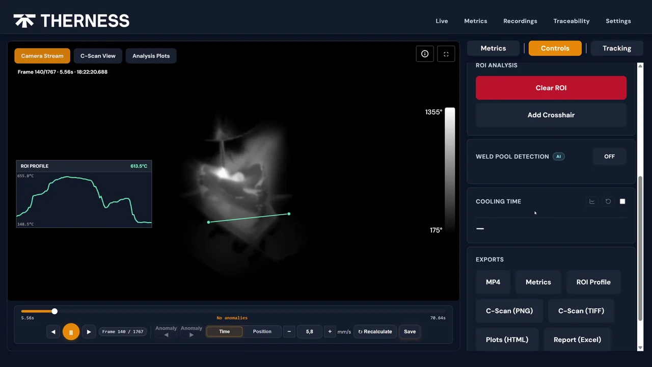
A welding defect prevention system stops non-conformances at the source — before scrap accumulates, before rework schedules slip, and before audit evidence goes missing. Engineers who wait for post-weld inspection to catch defects discover them at the worst possible moment: after the full production cost has been spent and the traceability window has closed. Inline monitoring intervenes at the weld itself, flagging off-parameter conditions in real time so the process team can correct root causes before a single joint becomes a rework case.
This guide quantifies what weld defects actually cost, compares inline monitoring against the traditional inspect-and-repair loop, and provides a step-by-step ROI model and implementation checklist for quality managers evaluating a welding defect detection system.
Key Takeaways
- Weld rework costs 3–10× the original production cost per joint; indirect costs (delays, penalties, scrap) push the true figure to 15–25×.
- Inline monitoring intercepts parameter drift before defects form, reducing the defect escape rate to post-weld inspection by 60–90% in controlled deployments.
- ISO 3834-2 and EN 15085-2 require documented weld parameter records — inline systems generate these automatically, replacing manual logbooks.
- Parameter-based monitoring covers process-induced defects (porosity, lack of fusion, undercut); adding a thermal camera extends coverage to spatial and surface non-conformances.
- A 50-repair/month fabricator can recover a USD 20,000 monitoring investment in under 12 months based on avoided rework cost alone.
- Inline monitoring does not replace post-weld inspection — it reduces the population of defective joints that inspection must find.
- Implementation runs 1–2 days for a pilot station; 3–8 weeks for a multi-station MES-integrated deployment.
Table of Contents
- What Welding Defect Prevention Actually Means
- The True Cost of Weld Rework and Scrap
- How Inline Monitoring Systems Prevent Defects
- Common Failure Modes and How Inline Systems Catch Them
- ROI Model: Build the Business Case
- Implementation Step-by-Step
- Standards and Validation Requirements
- FAQ
What Welding Defect Prevention Actually Means
Welding defect prevention is not the same as welding defect detection. Detection finds defects after they exist — through visual inspection per ISO 17637, radiography, UT, or PAUT. Prevention eliminates the conditions that produce defects in the first place.
Inline monitoring sits in the prevention tier. It tracks arc parameters — current (A), voltage (V), wire feed speed (m/min), travel speed (mm/min), shielding gas flow (l/min) — during every weld cycle and compares sampled values against the tolerance band defined in the qualified WPS. When a parameter drifts outside its window, the system alarms immediately: the operator can halt the run, adjust the process, and segregate the affected joint before the defect becomes a finished product.
This is fundamentally different from statistical process control applied after the shift. Post-hoc SPC tells you that something went wrong last Tuesday. Inline monitoring tells you it is going wrong in the next three seconds.
For facilities working to ISO 3834-2 or EN 15085-2, the monitoring record also satisfies the weld parameter documentation requirement directly — no manual logbook, no transcription error, no disputed traceability.
The True Cost of Weld Rework and Scrap
The cost of a welding defect is rarely the direct repair cost alone. Understanding the full cost structure is prerequisite to building a credible business case for monitoring.
Direct Repair Cost Breakdown
A typical weld repair cycle includes: arc gouging or grinding (removing the defective material), pre-heat re-application, re-welding with a qualified WPS, post-weld NDT repeat, and documentation update. Research published by TWI Global and the International Institute of Welding consistently places direct repair cost at 3–10× the original production cost per joint, driven by:
- Labour: the repair technician — often a more skilled welder than the production operator
- Machine time: the station is occupied during repair, blocking production throughput
- Consumables: electrodes, wire, shielding gas, and NDT consumables consumed twice
- Re-inspection: radiographer or UT operator time and report re-issue
For complex structural joints or pressure-boundary welds governed by ASME codes and standards, the ratio climbs further because re-inspection requires a Responsible Welding Coordinator sign-off and separate documentation entry.
Indirect and Hidden Costs
Direct repair cost is only the visible fraction. A breakdown of indirect costs for a 50-repair/month mid-size fabricator typically reveals:
| Cost category | Typical multiplier on direct repair cost |
|---|---|
| Schedule delay (delivery penalty or expediting) | 1.5–4× |
| Customer quality incident reporting | 0.5–2× |
| Internal audit and corrective action (8D) | 0.5–1× |
| Warranty and field rework (escaped defects) | 5–20× |
| Scrap on non-repairable parts | 3–8× |
For a detailed cost breakdown methodology, see the analysis in our weld defect cost and scrap reduction guide.
Escaped defects — defects not caught by post-weld inspection — generate field failures and warranty claims at 5–20× the cost of an in-process repair. Reducing the escape rate is the highest-leverage lever in defect cost reduction.
How Inline Monitoring Systems Prevent Defects
An inline weld monitoring system operates in two complementary layers: parameter-based monitoring and thermal imaging.
Parameter-Based Monitoring
The arc parameter layer samples welding current, voltage, wire feed speed, and travel speed at 1–10 ms intervals during every weld cycle. Each sample is compared against the WPS tolerance window:
- Current tolerance: typically ±10–15% of the qualified setpoint
- Voltage tolerance: typically ±1.5–2.5 V
- Wire feed speed tolerance: typically ±5–10% of setpoint
- Travel speed: derived from robot encoder or robot controller API
When a parameter breaches its tolerance for more than a configurable hold duration (commonly 200–500 ms to filter transient arc noise), the system raises an alarm and tags the affected weld segment with a non-conforming disposition. The weld segment ID, timestamp, parameter breach value, and alarm type are written to the traceability record automatically.
This automated record satisfies the monitoring clause of ISO 3834-2 without manual intervention — the most frequent gap cited in third-party audits.
Thermal Imaging for Spatial Coverage
Parameter monitoring is process-side: it knows the inputs but not always the weld geometry outcome. A welding camera or infrared thermal sensor adds the output view — capturing inter-pass temperature, heat-affected zone geometry, surface temperature profiles, and pool behaviour during solidification.
Thermal monitoring catches failure modes that parameter monitoring misses:
- Weld bead placement error caused by robot path drift
- Insufficient inter-pass cooling, which raises the risk of hydrogen-induced cracking
- Incomplete fusion at the weld toe on multi-pass joints where the arc parameters looked acceptable
- Arc start porosity that occurs within the first 100 ms before parameter averages stabilise
The combination of parameter monitoring and thermal imaging covers the widest defect prevention envelope available with inline technology. For a detailed look at the full spectrum of weld defects and their root causes, see the welding defects guide: types, causes, and acceptance criteria.
Common Failure Modes and How Inline Systems Catch Them
The following table maps the most frequent production-welding failure modes to the monitoring signal that intercepts them, and the alarm action that follows. Watch an unstable arc heading for rejection to see the kind of live signature these alarms key on.
| Defect | Root cause | Parameter signal | Thermal signal | Alarm action |
|---|---|---|---|---|
| Porosity | Gas deviation, contamination | Gas flow alarm | Surface bubble pattern | Flag segment, purge check |
| Lack of fusion | Low heat input, poor fit-up | Current < lower limit | Cold HAZ footprint | Flag segment, fit-up re-inspection |
| Undercut | Excessive voltage, high travel | Voltage > upper limit | Overheated toe signature | Flag segment, parameter re-qualification |
| Burn-through | Travel speed drop, fixture gap | Travel speed < lower limit | High-temp pool expansion | Pause, inspect joint geometry |
| Arc start porosity | Cold workpiece, short initial arc | Voltage spike < 100 ms | Early-cycle cold pool | Pre-heat check trigger |
| Incomplete penetration | Low WFS, short contact-to-work | WFS and voltage correlated low | Narrow pool, low rear-bead temp | Flag segment, adjust CTWD |
Porosity, lack of fusion, and undercut account for approximately 75% of all weld repairs in structural and pressure-boundary fabrication. Inline monitoring targets exactly this cluster with real-time alarm logic before the joint leaves the fixture.
ROI Model: Build the Business Case
The business case for an inline welding defect prevention system rests on four inputs: current defect rate, repair cost per event, system investment, and expected defect reduction rate. The model below is calibrated for a medium-volume structural fabricator.
Inputs and calculation:
| Parameter | Example value | Your value |
|---|---|---|
| Monthly weld volume (joints) | 2,500 | |
| Current defect rate | 2% → 50 repairs/month | |
| Direct repair cost per event (USD) | 400 | |
| Indirect cost multiplier | 3× | |
| Total monthly rework cost (USD) | 50 × 400 × 3 = 60,000 | |
| Expected defect reduction with monitoring | 70% | |
| Monthly cost avoided (USD) | 60,000 × 0.70 = 42,000 | |
| System investment (USD, 5-station) | 20,000 | |
| Payback period | < 1 month |
This model is conservative: it excludes avoided customer incidents, reduced audit exposure under ISO 3834-2, and the quality premium that certification enables in tenders. Use the welding quality ROI calculator to model your specific defect rate and repair cost.
Where monitoring delivers the highest leverage:
- Facilities with a repair rate above 1.5% on structural or pressure-boundary welds
- Lines with EN 15085 CL1/CL2 or ASME Section IX obligations where rework triggers re-qualification
- OEM suppliers with customer-imposed corrective action cost-recovery clauses
Decision framework — select monitoring scope by defect driver:
| Primary defect type | Monitoring recommendation |
|---|---|
| Porosity, undercut, burn-through | Parameter monitoring (current, voltage, WFS, travel speed) |
| Lack of fusion, incomplete penetration | Parameter monitoring + inter-pass temperature check |
| Robot path drift, bead placement error | Thermal camera mandatory |
| Multi-pass joints, hydrogen cracking risk | Thermal camera + inter-pass cooling timer |
| All of the above (structural / rail) | Full parameter + thermal integration |
Implementation Step-by-Step
Deploying an inline weld monitoring system follows a repeatable pattern regardless of the monitoring technology chosen.
Step 1 — Baseline the current defect rate. Pull 90 days of repair log data, categorise by defect type and weld process, and compute cost per event. This becomes the ROI denominator and the guard against inflated payback claims after deployment.
Step 2 — Define the monitoring scope. For MIG/MAG, robotic TIG, and SAW: parameter monitoring covers 80–90% of the defect space. For laser welding, keyhole TIG, or joints with tight geometric tolerances: add thermal imaging from day one.
Step 3 — Configure WPS tolerance windows. Extract qualified parameter ranges from your WPS set and enter them as alarm thresholds. Involve your Responsible Welding Coordinator: thresholds too tight generate nuisance alarms; too wide and real drift goes undetected. Typical starting tolerance: ±10% current, ±2 V voltage, ±8% WFS.
Step 4 — Run a 2-week pilot on the highest-defect station. Log all alarms, cross-reference with the post-weld inspection log, and compute the true positive rate. Adjust tolerance windows based on pilot data before fleet rollout.
Step 5 — Connect to MES or quality system. Export the monitoring record via REST API, OPC-UA, or CSV. The record must link weld segment ID to part serial number to satisfy the traceability clause of ISO 3834-2.
Step 6 — Train operators and inspectors. Operators need to understand alarm dispositions: hold, re-inspect, or scrap. Inspectors shift from 100% post-weld inspection to risk-based: alarmed segments at 100%, non-alarmed segments at the sampling rate the procedure allows.
Step 7 — Expand to fleet and track improvement. Roll out station by station, applying pilot-validated tolerance windows. Track the monthly defect rate against baseline monthly. Contact our engineering team for multi-station integration support and on-site commissioning.
Standards and Validation Requirements
Inline monitoring satisfies several audit and standards requirements simultaneously:
ISO 3834-2 (Comprehensive quality requirements for fusion welding) mandates in clause 8: documented monitoring of welding parameters and retention of weld records. Inline monitoring generates parameter logs automatically and links them to the weld order — closing the most common ISO 3834-2 audit gap identified in third-party assessments.
EN 15085-2 (Welding of railway vehicles and components) requires continuous monitoring of current, voltage, and travel speed for CL1 and CL2 joints. The standard explicitly positions automated monitoring as the compliance method for high-duty rail joints.
AWS D1.1 (Structural Welding Code — Steel) Section 6 requires WPS parameter compliance records. Inline monitoring provides these records in a format directly usable as compliance evidence in customer and third-party audits.
ISO 5817 defines the acceptance criteria for the defect types that inline monitoring targets. Pairing alarm thresholds with the corresponding ISO 5817 acceptance levels (B, C, or D) calibrates the system to actual acceptance criteria — not arbitrary engineering estimates.
VDA 6.3 P5: Audit questions P5.1–P5.4 assess the existence, documentation, and response to in-process welding monitoring evidence. A calibrated inline system with documented alarm history is the most direct response to P5.1 (“Are there defined monitoring and measurement activities during production?”).
Monitoring records are evidence of process control, not an acceptance certificate. Post-weld inspection per ISO 17637 and NDT to the applicable procedure remain required for structural, pressure-boundary, and rail joints regardless of monitoring outcome. Monitoring shifts where inspection effort is concentrated — it does not eliminate the inspection obligation.
For product specifications covering both parameter-monitoring and thermal imaging, see the PoolDrop weld pool monitor and HeatCam IR-C thermal imaging camera product pages. You can also browse the full inline-monitoring product range to compare configurations.
FAQ
What is a welding defect prevention system?
A welding defect prevention system combines inline process monitoring — arc parameters, thermal imaging, or pool geometry — with tolerance-based alarm logic tied to the qualified WPS. It detects parameter drift before off-condition cycles produce porosity, lack of fusion, or dimensional non-conformances, reducing the defect rate before post-weld inspection.
How does inline weld monitoring prevent welding defects?
Inline systems sample arc current, voltage, wire feed speed, and travel speed at millisecond intervals. When values drift outside WPS tolerances, the system flags the affected weld segment immediately — stopping defect accumulation before the batch is complete and traceability records are lost.
What welding defects can inline monitoring detect?
Parameter monitoring flags defects caused by process drift: porosity from gas deviation, lack of fusion from low heat input, undercut from excessive voltage, burn-through from speed drop. Adding a thermal camera extends detection to surface temperature excursions and geometric non-conformances.
How much does rework from welding defects cost?
Direct weld repair typically costs 3–10× the original production cost per joint: machining, gouging, re-welding, and NDT repeat add up fast. Indirect costs — schedule delay, customer penalties, and scrap for non-repairable parts — commonly push the true figure to 15–25× the original cost.
Which standards require welding defect prevention documentation?
ISO 3834-2 mandates documented monitoring of welding parameters. EN 15085-2 requires continuous monitoring of current, voltage, and travel speed for CL1/CL2 joints. AWS D1.1 Section 6 requires WPS compliance records. VDA 6.3 P5 audit questions directly assess in-process monitoring evidence.
Can inline monitoring replace post-weld inspection?
No. Inline monitoring reduces defect probability by catching process drift early, but ISO 3834, EN 15085, and AWS D1.1 still require post-weld visual inspection per ISO 17637 and NDT where specified. Process monitoring records are complementary traceability evidence, not a substitute for inspection results.
What is the typical ROI of an inline welding defect prevention system?
ROI depends on your defect rate and rework cost. A fabricator with 50 repairs/month at 3–10× direct cost per event can recover a USD 20,000 monitoring investment in under 12 months. Thermal camera coverage can further reduce escape rate and shorten payback.
How long does inline weld monitoring implementation take?
A single-station pilot with parameter monitoring takes 1–2 days. A multi-station deployment with WPS tolerance configuration and MES integration runs 3–8 weeks depending on station count and protocol complexity. Adding thermal camera sensors extends setup by 1–2 weeks per station for FOV calibration.
Prevent Welding Defects Before They Reach Inspection
Therness inline monitoring systems detect parameter drift in real time, generate ISO 3834-compliant traceability records automatically, and reduce weld repair costs from the first production shift.
Request a DemoTherness solution: Welding monitoring system — Every weld inspected in the cycle, with defect flags and the ISO 3834 / ISO 17635 evidence kept per weld.
Frequently Asked Questions
What is a welding defect prevention system?
A welding defect prevention system combines inline process monitoring — arc parameters, thermal imaging, or pool geometry — with tolerance-based alarm logic tied to the qualified WPS. It detects parameter drift before off-condition cycles produce porosity, lack of fusion, or dimensional non-conformances, reducing the defect rate before post-weld inspection.
How does inline weld monitoring prevent welding defects?
Inline systems sample arc current, voltage, wire feed speed, and travel speed at millisecond intervals. When values drift outside WPS tolerances, the system flags the affected weld segment immediately — stopping defect accumulation before the batch is complete and traceability records are lost.
What welding defects can inline monitoring detect?
Parameter monitoring flags defects caused by process drift: porosity from gas deviation, lack of fusion from low heat input, undercut from excessive voltage, burn-through from speed drop. Adding a thermal camera extends detection to surface temperature excursions and geometric non-conformances.
How much does rework from welding defects cost?
Direct weld repair typically costs 3–10× the original production cost per joint: machining, gouging, re-welding, and NDT repeat add up fast. Indirect costs — schedule delay, customer penalties, and scrap for non-repairable parts — commonly push the true figure to 15–25× the original cost.
Which standards require welding defect prevention documentation?
ISO 3834-2 mandates documented monitoring of welding parameters. EN 15085-2 requires continuous monitoring of current, voltage, and travel speed for CL1/CL2 joints. AWS D1.1 Section 6 requires WPS compliance records. VDA 6.3 P5 audit questions directly assess in-process monitoring evidence.
Can inline monitoring replace post-weld inspection?
No. Inline monitoring reduces defect probability by catching process drift early, but ISO 3834, EN 15085, and AWS D1.1 still require post-weld visual inspection per ISO 17637 and NDT where specified. Process monitoring records are complementary traceability evidence, not a substitute for inspection results.
What is the typical ROI of an inline welding defect prevention system?
ROI depends on your defect rate and rework cost. A fabricator with 50 repairs/month at 3–10× direct cost per event can recover a USD 20,000 monitoring investment in under 12 months. Thermal camera coverage can further reduce escape rate and shorten payback.
How long does inline weld monitoring implementation take?
A single-station pilot with parameter monitoring takes 1–2 days. A multi-station deployment with WPS tolerance configuration and MES integration runs 3–8 weeks depending on station count and protocol complexity. Adding thermal camera sensors extends setup by 1–2 weeks per station for FOV calibration.