Welding monitoring NADCAP compliance starts before the arc strikes. Under the AC7110/1 checklist, every fusion weld on flight-critical aerospace hardware must be backed by in-process evidence that parameters stayed within WPS limits — not just a post-weld inspection report declaring the joint acceptable.
This guide explains exactly what the AC7110 process monitoring clauses require, where suppliers generate audit findings, and how a real-time welding monitoring system satisfies those requirements with objective, timestamped data.
Key Takeaways
- AC7110/1 requires traceable in-process records — current, voltage, travel speed, preheat, and interpass temperature — for every production weld.
- Manual traveler entries are permitted but leave temporal gaps between readings; continuous automated monitoring eliminates those gaps entirely.
- The most common audit findings involve incomplete parameter records, interpass readings taken outside the specified measurement interval, and undocumented parameter deviations.
- Thermal imaging provides continuous preheat and interpass temperature measurement across the full joint width — not just a point-in-time pyrometer check — satisfying AC7110 thermal control clauses directly.
- Monitoring output must be traceable to the specific part identifier, WPS reference, and welder or operator to count as valid compliance evidence.
- AWS D17.1 and ISO 3834-2 both reinforce the in-process documentation requirements that NADCAP auditors check against AC7110.
- Implementing a monitoring system before your first NADCAP audit shortens preparation time significantly and reduces the risk of monitoring-related findings.
Table of Contents
- Why NADCAP Treats Welding as a Special Process
- What AC7110 Says About In-Process Monitoring
- The Six Parameters Auditors Want Documented
- Where Suppliers Fail on AC7110 Monitoring Items
- How Thermal Monitoring Closes the Evidence Gap
- Integrating Monitoring into Your NADCAP-Ready Workflow
- Common Failure Modes and Fixes
- Implementation Step-by-Step
- FAQ
Why NADCAP Treats Welding as a Special Process
NADCAP (National Aerospace and Defense Contractors Accreditation Program), managed by the Performance Review Institute, classifies welding as a special process because joint quality cannot be fully verified after completion without destructive testing. A weld that passes visual, dimensional, and radiographic inspection may still contain hydrogen-induced cold cracking, partially fused zones, or HAZ microstructure degradation that only emerges under service loading — sometimes years into the component lifecycle.
This is the same logic embedded in AWS D17.1 — Specification for Fusion Welding for Aerospace Applications: because the process governs the result, the process itself must be controlled, documented, and audited. You cannot inspect quality into a weld; you must build it in through verified process control.
The consequence for suppliers is that NADCAP welding accreditation is not an inspection program — it is a process control program. An auditor from PRI physically visits your facility, witnesses welding operations, and checks that every element of the AC7110/1 checklist is satisfied with objective evidence. For a complete overview of the overall audit scope and documentation framework, see our guide on NADCAP welding audit requirements and quality documentation.
What AC7110 Says About In-Process Monitoring
The AC7110/1 checklist organizes its process monitoring requirements under two primary domains: equipment control and in-process parameter verification.
Equipment control requires that welding power sources, wire feed systems, gas flow meters, preheat equipment, and any monitoring instrumentation used to generate production records are calibrated on a documented schedule. Calibration records must be traceable — serial number, calibration date, calibration expiry, and calibrating body — and must be available for auditor review during the on-site visit. An instrument that generated parameter records but carries an expired calibration certificate creates a finding against every weld it covered during the lapsed period.
In-process parameter verification is where most monitoring-related findings occur. AC7110/1 requires that during production welding, the following are checked and recorded in a form traceable to the specific part traveler:
- Welding current (A) and arc voltage (V), verified against WPS-qualified ranges for each pass
- Travel speed or wire feed rate, per the applicable process type
- Preheat temperature before arc initiation, measured at the correct distance from the joint per WPS
- Interpass temperature between passes, at the intervals and measurement distances specified in the WPS
- Heat input or arc energy (for processes where the WPS states a controlled heat input range)
- Shielding gas flow rate and gas type verification at the start of each session
AC7110/1 does not prescribe the monitoring technology. Manual traveler entries, chart recorder outputs, power source digital logs, or automated real-time monitoring system data streams are all accepted — provided the record is continuous or frequent enough to demonstrate parameter stability and is fully traceable to the weld joint.
The Six Parameters Auditors Want Documented
For GTAW and GMAW on aerospace structures, the parameter set that NADCAP auditors focus on most closely is:
| Parameter | AC7110/1 Domain | Typical Audit Question |
|---|---|---|
| Welding current (A) | Equipment and process control | Is actual current documented per pass against WPS limits? |
| Arc voltage (V) | Process parameter recording | Is actual voltage within the WPS range for each individual pass? |
| Travel speed (mm/min) | Process parameter recording | For mechanized welding, is speed logged? For manual, what is the check frequency? |
| Preheat temperature (°C) | Thermal control | What is the measurement method, distance from joint, and minimum dwell time? |
| Interpass temperature (°C) | Thermal control | At what frequency are readings taken, at what distance from the joint, and with what instrument? |
| Heat input or arc energy (kJ/mm) | WPS qualified range | Is calculated or measured heat input within the qualified limits for every pass? |
The preheat and interpass temperature items generate the most questions during NADCAP audits — not because suppliers fail to take readings, but because the readings are often taken in ways that do not satisfy the rigor the checklist implies. A contact pyrometer reading taken once at the start of a multi-pass sequence, well away from the joint fusion face, does not demonstrate interpass temperature control across the full welding sequence.
TWI Global’s welding knowledge resources provide authoritative reference material on heat input and interpass temperature measurement methodology that aligns with the evidence level NADCAP auditors expect. For deeper background on how heat input connects to HAZ microstructure, see our post on heat input, cooling rate, and t8/5 effects on weld quality.
Where Suppliers Fail on AC7110 Monitoring Items
Based on recurring NADCAP audit findings, the most common monitoring-related deficiencies fall into four categories:
- Incomplete traveler records — current, voltage, or travel speed columns left blank for individual passes, or only recorded at the start of a multi-pass sequence rather than per pass
- Interpass temperature coverage gaps — readings not taken at the WPS-specified intervals or measurement distances, or measured with an uncalibrated instrument
- Undocumented deviations — actual parameter excursions outside WPS limits that were not flagged, reviewed, or covered by a nonconformance disposition record
- Calibration expiry on monitoring equipment — pyrometers, contact thermometers, or power source monitoring systems used to generate production records with an expired or missing calibration certificate
The interpass temperature issue is particularly common on multi-pass thick-section joints where a manual pyrometer check every few minutes is practically difficult. A welder maintaining arc stability and travel angle cannot simultaneously monitor interpass temperature continuously across the joint. The result is either infrequent readings that leave coverage gaps, or estimated entries with no objective measurement basis.
NIST guidance on temperature measurement uncertainty underscores why auditors scrutinize measurement method: a pyrometer reading without documented emissivity setting, appropriate standoff distance, and calibration traceability carries significant uncertainty that undermines the validity of the record as compliance evidence.
How Thermal Monitoring Closes the Evidence Gap
A welding monitoring system addresses the most common AC7110 monitoring findings directly by replacing periodic manual readings with continuous, automated data capture synchronized to the welding arc.
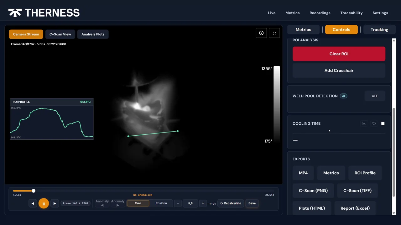
For preheat and interpass temperature — the two most finding-prone items — thermal imaging measures temperature across the full width of the joint and surrounding HAZ continuously throughout the welding sequence. Rather than a point-in-time pyrometer value, the monitoring system generates a complete temperature history showing not only that interpass temperature was within limits when manually checked, but that it remained within limits across every pass and every inter-pass interval. There are no coverage gaps, no estimations, and no reliance on welder memory for record completion. The HeatCam IR-C thermal camera provides exactly this continuous interpass thermal record across the full joint width.
For current and voltage monitoring, Therness WeldTrace records current, voltage, wire feed and gas for each weld; together with the thermal record of the same weld, it gives one in-process record per weld that covers both the thermal and electrical aspects of AC7110 monitoring requirements in a single timestamped data file.
The monitoring output is structured to integrate with existing production travelers: each weld pass record includes timestamp, parameter values with WPS limit comparison, pass number, and joint identifier cross-reference. An auditor can pull a traveler for any joint and retrieve the corresponding monitoring record demonstrating parameter compliance throughout. This approach to in-process traceability integrates directly with the broader compliance workflows described in our guide on ISO 3834 and EN 1090 welding traceability with thermography.
For a broader look at how infrared thermography in real-time welding quality monitoring compares to post-weld inspection approaches, that guide covers the thermal measurement fundamentals that underpin NADCAP-compatible monitoring. You can also watch real-time thermal imaging of a live weld to see continuous preheat and interpass capture in action.
Integrating Monitoring into Your NADCAP-Ready Workflow
Adding a monitoring system to an existing NADCAP-accredited workflow requires attention to three integration points:
1. WPS revision and qualification impact. If your current WPS does not reference in-process monitoring equipment, review whether adding it constitutes a significant change under your applicable standard (AWS D17.1 or AMS specifications from SAE International). The safest approach is to introduce the monitoring system as an optional auxiliary reference tool, not a mandatory process variable, so its presence does not affect the WPS qualification range.
2. Traveler and record structure. Define how monitoring data links to the traveler. The minimum required field is a unique monitoring session identifier or timestamp range cross-referencing each weld pass record on the traveler to its monitoring file. Monitoring output archives should be retained alongside traveler packages per your document control procedure with the same retention period.
3. Calibration program inclusion. The monitoring system must be included in your calibration schedule with the same rigor applied to contact pyrometers and power source calibration equipment. Calibration interval, method, and acceptance criteria should be defined in the calibration procedure and traceable to national measurement standards per NIST guidelines or equivalent national metrology institute. ASME standards for pressure equipment and aerospace fabrication also provide relevant guidance on measurement system calibration requirements.
Implementing monitoring before your first NADCAP audit significantly shortens preparation time. Auditors who can witness a functioning monitoring system during the observation weld — with parameter records appearing in real time, alarm thresholds visible, and output traceable to the traveler — tend to complete that section of the checklist efficiently. Suppliers relying solely on manual traveler records face more detailed questions about methodology, measurement equipment, coverage frequency, and calibration chains.
Common Failure Modes and Fixes
| Failure Mode | Root Cause | Fix |
|---|---|---|
| Missing interpass records on multi-pass joints | Manual pyrometer impractical during active welding | Deploy thermal monitoring with automated continuous logging; set temperature alert thresholds to WPS limits |
| Calibration finding on contact pyrometer | Annual calibration lapsed between jobs | Add all monitoring instruments to CMMS calibration schedule with advance alert 30 days before expiry |
| WPS parameter exceedance undocumented | No real-time alarm; welder didn’t notice drift | Configure monitoring system alert thresholds to WPS limits; archive alarm event log as part of the weld record |
| Heat input unrecorded for manual GTAW | Welder records current and voltage but not travel speed | Add arc-on-time logger or foot-switch event recorder to capture per-pass arc time for heat input derivation |
| Traveler–monitoring data mismatch at audit | Monitoring session IDs not cross-referenced to traveler pass records | Define a dedicated traveler field for monitoring session ID; mandate completion before traveler sign-off |
| Interpass readings taken outside specified distance | Welder takes shortcut measurement at edge of plate | Document measurement distance in work instruction; include as a specific witness check in supervisor sign-off |
Implementation Step-by-Step
-
Scope the monitoring need. Identify which processes and joint types in your NADCAP scope carry the highest monitoring finding risk — typically multi-pass GTAW or GMAW on thick sections (above 10 mm) with WPS-specified interpass temperature controls and heat input ranges.
-
Select monitoring configuration. For thermal control requirements, configure the infrared camera to cover the joint and at least 50 mm on each side to track interpass temperature across the full influence zone. Verify camera spatial resolution is appropriate for your minimum weld bead width; compare options across the Therness monitoring product range.
-
Define alarm thresholds. Set current, voltage, and temperature alert limits to match WPS-qualified ranges. Document these thresholds in the monitoring system configuration record — the configuration file is itself a quality document and must be revision-controlled.
-
Revise the traveler template. Add a field for monitoring session ID or timestamp range, linking each weld pass entry to its monitoring data file. This one field is what makes the entire record traceable from a single document.
-
Train welders and quality personnel. Welders must know how to start and stop monitoring sessions, verify the system is actively recording before arc initiation, and respond to parameter alarms. Quality personnel must know how to retrieve, archive, and cross-reference monitoring data files.
-
Run a validation witness weld. Before using monitoring data as AC7110 compliance evidence, run a witness weld under monitoring and verify the output record against a hand-completed traveler. Confirm all parameters appear, timestamps are correct, and alarm events (if triggered) are logged.
-
Include monitoring in the pre-audit self-assessment. Walk the monitoring system through the AC7110/1 checklist items for in-process parameter recording. Document specifically how each item is satisfied by the monitoring output versus supplementary manual records.
-
Contact a Therness welding monitoring specialist for guidance on configuring the system for your specific AC7110 scope, process types, and joint geometries before your next audit cycle.
FAQ
What does NADCAP require for welding process monitoring? AC7110/1 requires suppliers to document in-process parameters — welding current, voltage, travel speed, wire feed rate, preheat and interpass temperature — for every production weld. Evidence must be traceable to the specific part, WPS, and welder. Real-time monitoring systems that log and timestamp parameter streams satisfy this requirement more reliably than manual traveler records.
Is real-time monitoring required by AC7110? AC7110/1 does not mandate a specific monitoring technology but requires objective, traceable evidence that WPS parameters were maintained throughout welding. Manual records are accepted but leave gaps: readings are periodic, not continuous. A real-time monitoring system provides continuous parameter logging that directly satisfies the intent of AC7110 in-process control clauses.
What parameters must be recorded during NADCAP-controlled welding? The minimum AC7110/1 parameter set includes welding current, arc voltage, travel speed (or wire feed rate for semi-automatic processes), preheat temperature, and interpass temperature. For processes requiring heat input calculation (GTAW, GMAW, PAW), the actual heat input or arc energy value per pass must be derivable from the records.
How does thermal imaging support NADCAP AC7110 compliance? Thermal imaging provides continuous measurement of preheat and interpass temperature across the full joint width, detects HAZ width deviations that indicate heat input drift, and generates a timestamped temperature log per weld pass. This data satisfies AC7110 in-process control documentation requirements and provides objective evidence during the audit witness test.
What is the difference between NADCAP welding and ISO 3834? ISO 3834 is a quality management framework for welding that can be self-declared or third-party certified. NADCAP is an audit-based accreditation: a PRI auditor physically witnesses welding operations and reviews records against the AC7110 checklist. ISO 3834 supports NADCAP readiness but does not substitute for it.
Which aerospace primes require NADCAP welding accreditation? Most aircraft, engine and defence primes, and most Tier 1 OEMs, require NADCAP welding accreditation for suppliers performing fusion welding on flight-critical hardware. The specific requirement appears in the supplier quality requirements document accompanying each purchase order.
Can a thermal monitoring system replace NADCAP documentation? No. Thermal monitoring is a tool that generates evidence — it does not replace the documentation framework (WPS, PQR, qualified welder records, calibration logs, traveler). Monitoring output integrates with the traveler as an objective in-process record that supplements rather than replaces paper-based documentation.
What are the most common NADCAP welding audit failures related to monitoring? The most frequent monitoring-related findings are: missing or incomplete in-process parameter records on production travelers, interpass temperature readings taken at incorrect intervals or distances from the weld, undocumented deviations from WPS current/voltage ranges, and calibration gaps on monitoring equipment used to generate production records.
NADCAP audit coming up? Get your monitoring evidence ready.
Therness welding monitoring systems provide continuous, traceable in-process records that satisfy AC7110/1 requirements for thermal control and parameter documentation. Speak with a specialist about your specific audit scope and process types.
Talk to a Monitoring SpecialistTherness solution: Welding monitoring system — Every weld inspected in the cycle, with defect flags and the ISO 3834 / ISO 17635 evidence kept per weld.
Frequently Asked Questions
What does NADCAP require for welding process monitoring?
AC7110/1 requires suppliers to document in-process parameters — welding current, voltage, travel speed, wire feed rate, preheat and interpass temperature — for every production weld. Evidence must be traceable to the specific part, WPS, and welder. Real-time monitoring systems that log and timestamp parameter streams satisfy this requirement more reliably than manual traveler records.
Is real-time monitoring required by AC7110?
AC7110/1 does not mandate a specific monitoring technology but requires objective, traceable evidence that WPS parameters were maintained throughout welding. Manual records are accepted but leave gaps: readings are periodic, not continuous. A real-time monitoring system provides continuous parameter logging that directly satisfies the intent of AC7110 in-process control clauses.
What parameters must be recorded during NADCAP-controlled welding?
The minimum AC7110/1 parameter set includes welding current, arc voltage, travel speed (or wire feed rate for semi-automatic processes), preheat temperature, and interpass temperature. For processes requiring heat input calculation (GTAW, GMAW, PAW), the actual heat input or arc energy value per pass must be derivable from the records.
How does thermal imaging support NADCAP AC7110 compliance?
Thermal imaging provides continuous measurement of preheat and interpass temperature across the full joint width, detects HAZ width deviations that indicate heat input drift, and generates a timestamped temperature log per weld pass. This data satisfies AC7110 in-process control documentation requirements and provides objective evidence during the audit witness test.
What is the difference between NADCAP welding and ISO 3834?
ISO 3834 is a quality management framework for welding that can be self-declared or third-party certified. NADCAP is an audit-based accreditation: a PRI auditor physically witnesses welding operations and reviews records against the AC7110 checklist. ISO 3834 supports NADCAP readiness but does not substitute for it. Many aerospace primes require both.
Which aerospace primes require NADCAP welding accreditation?
Most aircraft, engine and defence primes, and most Tier 1 OEMs, require NADCAP welding accreditation for suppliers performing fusion welding on flight-critical hardware. The specific requirement appears in the supplier quality requirements document accompanying each purchase order.
Can a thermal monitoring system replace NADCAP documentation?
No. Thermal monitoring is a tool that generates evidence — it does not replace the documentation framework (WPS, PQR, qualified welder records, calibration logs, traveler). Monitoring output integrates with the traveler as an objective in-process record that supplements rather than replaces paper-based documentation.
What are the most common NADCAP welding audit failures related to monitoring?
The most frequent monitoring-related findings are: missing or incomplete in-process parameter records on production travelers, interpass temperature readings taken at incorrect intervals or distances from the weld, undocumented deviations from WPS current/voltage ranges, and calibration gaps on monitoring equipment used to generate production records.