Welding process control software closes the gap between a qualified WPS on paper and repeatable, documented compliance at every weld bead. Engineers who rely solely on post-weld inspection discover defects after the fact — at full scrap cost or rework time. A monitoring system that tracks current, voltage, wire feed speed, and travel speed in real time gives the weld engineer early warning before off-parameter conditions produce defects, and generates the traceability record required by ISO 3834-2, EN 15085-2, and customer-specific quality plans.
This guide covers the core features to evaluate, what each market tier costs, how to implement from pilot to fleet, and a decision framework scaled to your audit obligation and station count.
Key Takeaways
- Welding process control software monitors arc parameters in real time and alerts when values drift outside WPS tolerances — catching process faults before defects form.
- ISO 3834-2 and EN 15085-2 require documented weld parameter records; dedicated software generates these automatically, replacing manual logbooks.
- Cost ranges from USD 500–2,000 (embedded power-source module) to USD 20,000–80,000+ (enterprise fleet platform with predictive analytics).
- OPC-UA, MQTT, and REST API are the standard integration protocols; verify PLC and MES compatibility before committing to a platform.
- Process control software does not replace post-weld inspection — it reduces defect probability and provides mandatory traceability evidence.
- A single-station pilot takes 1–2 days; a multi-station MES-integrated rollout runs 4–12 weeks.
- Select the platform tier based on your audit obligation (ISO 3834-2, EN 15085, VDA 6.3), weld process mix, and MES integration depth.
Table of Contents
- What Is Welding Process Control Software?
- Core Features to Evaluate
- Common Failure Modes and How to Avoid Them
- Cost Range by Platform Tier
- Implementation Step-by-Step
- Which Welding Processes Are Supported?
- Decision Framework: How to Choose
- FAQ
What Is Welding Process Control Software?
Welding process control software is an industrial monitoring layer that sits between your welding equipment and your quality records. At minimum, it samples arc parameters — welding current (A), arc voltage (V), wire feed speed (m/min), travel speed (mm/min), and shielding gas flow — at high resolution (typically 1–10 ms intervals) during every weld cycle.
The software compares each sampled value against the tolerance window defined in the approved Welding Procedure Specification. When a parameter drifts outside tolerance, the system triggers an alarm, marks the weld as non-conforming in the record, or sends a stop signal to the robot or positioner. After the weld cycle, it stores a complete parameter record — linked to part ID, weld ID, operator ID, and timestamp — that serves as evidence for ISO 3834-2 clause 9 weld records or EN 15085-2 CL1/CL2 monitoring requirements.
More advanced platforms add arc stability scoring, heat input calculation (kJ/mm per EN 1011-1 annex C), defect prediction heuristics based on historical parameter patterns, and fleet-level dashboards for quality managers.
The practical difference between a plant with and without process control software is where defects surface: in-process (immediate correction at zero part cost) versus post-weld inspection (rework or scrap at full part value).
For manufacturers operating under EN 15085-2 certification level CL1 or CL2, continuous monitoring of current, voltage, and travel speed is mandatory — not optional — for each weld run. Embedded power-source modules that report only shift-level averages do not satisfy this requirement.
Core Features to Evaluate
Real-Time Parameter Monitoring
The baseline capability. Look for:
- Sampling rate: 1 ms or better for MIG/MAG pulse processes; 100 ms is acceptable for SAW. Slower sampling misses transient faults such as arc extinction, short-circuit spatter events, or wire bird-nesting at the liner.
- Measurement accuracy: current ±1 A, voltage ±0.1 V. Some power-source integrations report controller set-points rather than actual arc values — verify the system reads from current transducers (shunt or Hall-effect sensor), not from the welding controller command register.
- Per-weld segmentation: the software must correlate parameters to individual weld beads by seam ID, not only to operator shift or work order. Without weld-level granularity, a single non-conforming pass cannot be isolated in the record.
Data Logging and Traceability
ISO 3834-2 clause 9 requires retention of welding procedure documents and welding records. The software must:
- Generate immutable logs with a timestamp and weld ID — no edit-in-place capability.
- Link weld records to part serial number or batch ID, the minimum for AS/EN 9100, IATF 16949, or rail EN 15085 supply chains.
- Export to PDF or CSV for audit packs without manual reformatting.
Systems with electronic signature support compliant with FDA CFR 21 Part 11 are required for medical and aerospace customers.
Alarm and Rejection Thresholds
Tolerance logic must reflect the WPS qualified under EN ISO 15614-1 or the applicable procedure qualification standard. Features to verify:
- Per-parameter high/low thresholds configurable per WPS revision — not global defaults.
- Time-in-fault reporting: alarm only if a fault persists beyond a configurable minimum duration (typically 200 ms) to filter transient arc re-ignition and controlled dip phases in pulse MIG.
- Automatic weld disposition: mark the weld record “non-conforming” when any threshold is exceeded without requiring operator intervention.
MES and ERP Integration
For manufacturers with an existing MES or ERP, integration is non-negotiable for production traceability. Standard protocols used by current platforms:
| Protocol | Typical use case |
|---|---|
| OPC-UA | Industrial control network to SCADA/MES |
| MQTT | IoT edge-to-cloud telemetry |
| REST API | ERP integration |
| PROFINET / EtherNet/IP | Robot controller and PLC integration |
| Modbus TCP | Legacy PLC and peripheral integration |
Require a published API specification and a sandbox test environment from the vendor. Proprietary data formats without documented APIs create long-term vendor lock-in and complicate future MES migrations.
TWI Global’s analysis of welding digitalization and Industry 4.0 consistently identifies data interoperability — the ability to exchange weld records between monitoring systems and production systems — as the highest-value driver of welding quality ROI. Closed-format platforms that cannot export structured data to MES routinely underperform their projected ROI by 30–50%.
Common Failure Modes and How to Avoid Them
Measuring Set-Points Instead of Actual Arc Values
Some power-source-embedded modules report the controller’s command register (the programmed set-point) rather than actual arc current and voltage at the electrode. Set-points stay within WPS tolerance by definition — they never detect contact tip degradation, liner blockage, or electrode misalignment that cause actual arc values to drift into the defect zone.
Fix: Confirm with the vendor in writing that measurements come from current transducers and voltage probes connected directly to the welding circuit — not from the power source’s internal command register. Request sample data logs showing the raw measurement channel, not a derived set-point confirmation value.
Alarm Flooding and Operator Desensitization
Threshold bands set directly at WPS nominal ±5% generate hundreds of alarms per shift: arc re-ignition transients, controlled dip phases in pulse MIG, and normal process variation all trigger false positives. Operators acknowledge and disable alarm notifications within the first week.
Fix: Set threshold bands at ±10–15% of WPS mid-range (or derived from the actual statistical process distribution during procedure qualification), and configure a minimum fault duration of 200–500 ms. Review alarm rate weekly during the first month of commissioning and tighten thresholds only after operators have built trust in the system.
Missing Weld ID Correlation
Software that logs parameters by shift or work order cannot link a non-conforming weld record to the specific joint in the part. This invalidates the traceability record for EN 15085-2 CL1 requirements and for VDA 6.3 P5 audit evidence — auditors will mark it as a critical finding.
Fix: Require weld ID to be generated per-cycle and linked to part serial number and seam/joint number. Trigger weld ID assignment from the robot program or PLC signal — not from manual operator entry that can be bypassed when operators are under production pressure.
Neglecting Heat Input Calculation
EN 15085-2 and many structural welding standards impose heat input limits as a quality criterion alongside current and voltage tolerances. Software that monitors electrical parameters but does not calculate heat input (Q = (U × I × 60) / (v × 1000) kJ/mm, where v is travel speed in mm/min) cannot verify this requirement without a separate manual spreadsheet calculation — a gap that auditors routinely identify.
Fix: Confirm that the platform calculates and logs heat input per weld pass automatically using measured (not estimated) travel speed, either from encoder feedback or from the robot controller integration.
Cost Range by Platform Tier
| Tier | Description | Cost per station (hardware + software) |
|---|---|---|
| Embedded module | Built into the welding power source; monitors current/voltage only; basic data export | USD 500–2,000 |
| Standalone monitoring system | External hardware + software; full parameter set + traceability + alarm logic; optional MES integration | USD 3,000–15,000 |
| Inline NDT integration | Parameter monitoring + thermal camera or arc emission sensor; defect detection beyond parameter drift | USD 8,000–25,000 |
| Enterprise fleet platform | Multi-station, multi-site; predictive analytics; full MES/ERP integration; advanced dashboards | USD 20,000–80,000+ for 20–50 stations |
Annual software licensing and maintenance adds 15–25% of initial cost per year. Cloud-hosted platforms use a SaaS subscription model (per-station/month), which shifts capital expenditure to operating expenditure but typically increases total cost of ownership over a 5-year horizon.
IIW Commission XII studies on welding data utilization show that inline process monitoring reduces MIG/MAG rework rates by 30–60% in high-volume production, with payback periods of 12–24 months for lines producing more than 500 weld cycles per shift per station.
Implementation Step-by-Step
-
Baseline audit: document current defect rate, rework cost per joint type, and inspection intervals. This becomes the pre-implementation benchmark for ROI measurement and the justification for budget approval.
-
WPS tolerance mapping: for each WPS in scope, extract minimum/maximum acceptable values for current, voltage, wire feed speed, and travel speed from the qualified procedure record. These values — not the machine set-points — form the threshold table for the software configuration.
-
Pilot station selection: choose a high-volume, single-process, single-position station for the first installation. Avoid starting on a multi-process or multi-position station — too many independent variables to isolate during commissioning.
-
Hardware installation and validation: mount current transducers and voltage probes directly on the welding circuit. Validate measurements against a calibrated clamp meter and certified voltage reference before producing any weld records. The monitoring data is only as accurate as the sensor installation.
-
Threshold commissioning: run 20–30 production welds per WPS under normal conditions and review the parameter distribution. Set thresholds to the WPS qualified range — not the statistical process distribution. The WPS range is the compliance boundary; the process distribution shows where you currently operate within it.
-
Alarm rate review: target <5 alarms per 100 welds in steady state. Higher rates indicate either misconfigured thresholds or a process problem that needs correction before further software tuning.
-
MES integration and weld ID handshake: configure weld ID triggers from the robot program or PLC. Validate end-to-end that each weld record in the monitoring software matches the corresponding joint record in the MES — test with intentional parameter violations and verify that non-conforming records propagate correctly.
-
Operator training: 2–4 hours per operator focused on interpreting alarm types and responding to non-conforming weld dispositions. Training records are required under ISO 3834-2 clause 12 (personnel qualification and responsibility).
-
30-day pilot review: after one month of production data, present the weld record summary, alarm rate trend, and defect rate comparison to your quality auditor. Use their feedback to refine thresholds and reporting before fleet rollout.
Which Welding Processes Are Supported?
| Process | Monitoring approach | Notes |
|---|---|---|
| MIG/MAG (GMAW) | Current, voltage, WFS, travel speed | Widest commercial support; all tiers available |
| TIG (GTAW) | Current, travel speed, gas flow | Orbital TIG requires integration with the orbital head controller |
| FCAW | Current, voltage, WFS | Same sensor set as MIG/MAG |
| SAW | Current, voltage, travel speed, wire feed | High heat input → heat input monitoring is critical |
| Laser beam welding | Power output, travel speed, focus position | Thermal camera integration recommended for melt pool monitoring |
| Resistance spot (RSW) | Current, force, weld time, resistance | Dedicated RSW monitoring; electrical arc monitoring does not apply |
| Plasma arc (PAW) | Current, gas flow, travel speed | Narrower commercial coverage; verify vendor support explicitly |
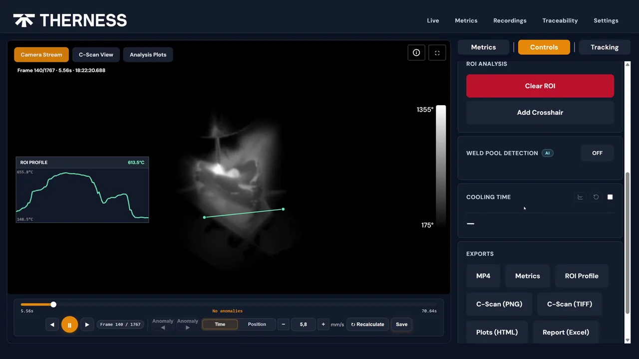
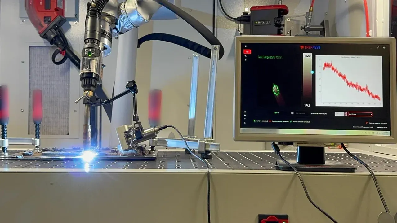
For laser welding and keyhole TIG, electrical parameter monitoring alone cannot detect subsurface melt pool defects. Coupling the process control software with a thermal imaging system provides melt pool geometry and solidification temperature data that arc parameters cannot capture. Therness’s welding monitoring system integrates arc parameter data with thermal imaging for these hybrid monitoring requirements, bridging the gap between process compliance monitoring and inline defect detection. To see how the combined arc-and-thermal capture runs on a live station, watch the system overview walkthrough.
Decision Framework: How to Choose
Use this table to identify your minimum viable platform tier based on audit obligation and operational requirements:
| Criterion | Embedded module | Standalone system | Enterprise platform |
|---|---|---|---|
| Audit obligation | ISO 9001 only | ISO 3834-2 / EN 15085 / AWS D1.1 | VDA 6.3 / NADCAP / AS 9100 |
| Station count | 1–5 | 5–25 | 25+ |
| MES/ERP integration required | No | Optional | Mandatory |
| Traceability to part serial number | No | Yes | Yes |
| Heat input per pass | No | Yes (most) | Yes |
| Predictive analytics / fleet KPIs | No | No | Yes |
| Typical payback period | <12 months | 12–24 months | 18–36 months |
Selection rules by audit obligation:
- ISO 3834-2 customer requirement: minimum Standalone system with per-weld traceability and MES export.
- EN 15085-2 CL1/CL2: Standalone system or Inline NDT integration with continuous per-pass monitoring and heat input calculation.
- AWS D1.1 structural welding or ASME B31.3 process piping: Standalone system with WPS tolerance configuration and per-weld export.
- VDA 6.3 P5 automotive: Standalone with documented MES API integration, or Enterprise platform — P5 auditors expect fleet-level statistics and corrective action traceability.
- ISO 9001 only, <5 stations, no audit record obligation: Embedded module is sufficient for process consistency tracking.
For manufacturers evaluating complementary inline NDT alongside process parameter monitoring, Therness PoolDrop inline arc monitoring covers electrical process compliance monitoring while HeatCam IR-C thermal imaging detects melt pool geometry anomalies that parameter monitoring alone cannot resolve — particularly relevant for laser welding and keyhole TIG applications. Both units sit within the full monitoring product range, so you can scale a tier to your station count and audit obligation.
For guidance on WPS management platforms that feed tolerance data into monitoring systems, see our overview of WPS management software options.
The post-weld acceptance gates that process control software is designed to prevent reaching are defined in ISO 5817 acceptance criteria and ASME B31.3 process piping welding and inspection requirements. Reviewing both in context of your monitoring setup clarifies which defect types your current parameter thresholds address and which require supplementary NDT.
Additional independent benchmarks on monitoring system performance and welding digitalization ROI are available from TWI Global’s technical knowledge base and IIW’s welding quality resources.
FAQ
What is welding process control software?
Welding process control software monitors and logs real-time arc parameters — current, voltage, wire feed speed, travel speed, and shielding gas flow — during every weld cycle. It compares sampled values against qualified WPS tolerances and triggers alarms or non-conforming dispositions when parameters drift outside the acceptable window.
What features should welding process control software include?
Essential features include real-time parameter monitoring, tolerance-based alarm logic tied to the approved WPS, per-weld traceability records linked to part serial number, audit-ready report export, and open integration APIs for MES/ERP. Secondary features include arc stability scoring, heat input calculation, defect prediction heuristics, and multi-station fleet dashboards.
How much does welding process control software cost?
Embedded power-source monitoring modules cost USD 500–2,000 per station. Standalone industrial systems with full traceability and MES integration range from USD 3,000–15,000 per station. Enterprise fleet platforms with predictive analytics and multi-site management typically cost USD 20,000–80,000+ for 20–50 stations. Annual software maintenance adds 15–25% of initial cost.
Can welding process control software integrate with existing PLCs and MES?
Yes. Current platforms support OPC-UA, MQTT, and REST API for MES/SCADA integration, and PROFINET, EtherNet/IP, and Modbus TCP for direct connection to robot controllers and PLCs. Always verify protocol compatibility with your robot vendor and MES supplier before purchasing.
Does welding process control software replace manual inspection?
No. Process monitoring reduces defect probability by catching parameter drift before defects consolidate, but it does not replace post-weld inspection. ISO 3834-2, EN 15085-2, and AWS D1.1 still require visual inspection per ISO 17637 and NDT where specified. Process control records are complementary traceability evidence, not a substitute for inspection results.
Which welding processes are compatible with real-time process control software?
MIG/MAG (GMAW), TIG (GTAW), FCAW, SAW, plasma arc (PAW), laser beam welding (LBW), and resistance spot welding (RSW) are supported by current commercial platforms. Laser welding and keyhole TIG often require additional thermal camera or arc emission sensors beyond electrical parameter monitoring alone.
How long does welding process control software implementation take?
A single-station pilot with an embedded power-source module takes 1–2 days. A multi-station rollout with MES integration, WPS tolerance configuration, and operator training runs 4–12 weeks depending on plant size, protocol complexity, and existing network infrastructure.
What welding quality standards require documented process control?
ISO 3834-2 mandates documented monitoring of welding parameters and retention of weld records. EN 15085-2 requires continuous monitoring of current, voltage, and travel speed for CL1/CL2 joints. AWS D1.1 requires WPS parameter compliance records for structural welds. VDA 6.3 P5 audit questions directly assess the existence and adequacy of in-process welding monitoring evidence.
See Welding Process Control in Action
Therness combines inline arc parameter monitoring with thermal imaging so you capture both electrical compliance and melt pool quality in a single system. Book a technical demonstration to see how it integrates with your current WPS and MES.
Book a demonstrationTherness solution: Welding parameter monitoring — Current, voltage, wire feed and gas recorded per weld, as WPS/PQR and heat-input evidence.
Frequently Asked Questions
What is welding process control software?
Welding process control software monitors and logs real-time arc parameters — current, voltage, wire feed speed, travel speed, and shielding gas flow — during every weld cycle. It compares sampled values against qualified WPS tolerances and triggers alarms or non-conforming dispositions when parameters drift outside the acceptable window.
What features should welding process control software include?
Essential features include real-time parameter monitoring (current, voltage, WFS, travel speed), tolerance-based alarm logic tied to the approved WPS, per-weld traceability records linked to part serial number, audit-ready report export, and open integration APIs for MES/ERP. Secondary features include arc stability scoring, heat input calculation, defect prediction heuristics, and multi-station fleet dashboards.
How much does welding process control software cost?
Embedded power-source monitoring modules cost USD 500–2,000 per station. Standalone industrial systems with full traceability and MES integration range from USD 3,000–15,000 per station. Enterprise fleet platforms with predictive analytics and multi-site management typically cost USD 20,000–80,000+ for 20–50 stations. Annual software maintenance adds 15–25% of initial cost.
Can welding process control software integrate with existing PLCs and MES?
Yes. Current platforms support OPC-UA, MQTT, and REST API for MES/SCADA integration, and PROFINET, EtherNet/IP, and Modbus TCP for direct connection to robot controllers and PLCs. Always verify protocol compatibility with your robot vendor and MES supplier before purchasing — proprietary closed-format systems frequently block integration.
Does welding process control software replace manual inspection?
No. Process monitoring reduces defect probability by catching parameter drift before defects consolidate, but it does not replace post-weld inspection. ISO 3834, EN 15085, and AWS D1.1 still require visual inspection per ISO 17637 and NDT where specified. Process control records are complementary traceability evidence, not a substitute for inspection results.
Which welding processes are compatible with real-time process control software?
MIG/MAG (GMAW), TIG (GTAW), FCAW, SAW, plasma arc (PAW), laser beam welding (LBW), and resistance spot welding (RSW) are supported by current commercial platforms. Laser welding and keyhole TIG often require additional thermal camera or arc emission sensors beyond electrical parameter monitoring alone.
How long does welding process control software implementation take?
A single-station pilot with an embedded power-source module takes 1–2 days. A multi-station rollout with MES integration, WPS tolerance configuration, and operator training runs 4–12 weeks depending on plant size, protocol complexity, and existing network infrastructure.
What welding quality standards require documented process control?
ISO 3834-2 mandates documented monitoring of welding parameters and retention of weld records. EN 15085-2 requires continuous monitoring of current, voltage, and travel speed for CL1/CL2 joints. AWS D1.1 Section 6 requires WPS parameter compliance records for structural welds. VDA 6.3 P5 audit questions directly assess the existence and adequacy of in-process welding monitoring evidence.