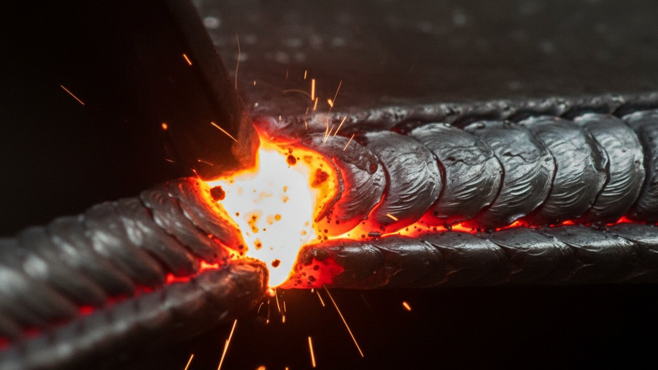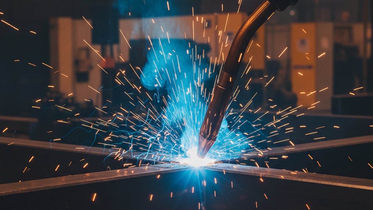
Wire feed speed is the single control that decides how wide, how tall, and how well-fused each bead is when wire arc additive manufacturing (WAAM) builds a metal wall bead by bead. Watch the footage below in slow motion and the mechanism is visible: a moving arc melts wire fed continuously from a spool, and the resulting pool freezes into a ridge whose cross-section depends entirely on how much metal landed in how much time.
That relationship is also the most common source of WAAM build failures. Get it wrong and the wall humps, slumps, or fails to fuse to the layer beneath it; get it right and every layer becomes a repeatable building block. This guide covers the mechanism, what correct and incorrect bead formation look like on camera, and a step-by-step procedure for setting and verifying wire feed speed on a real build.
Key Takeaways
- Bead width and height in WAAM are governed primarily by the ratio of wire feed speed (WFS) to travel speed, not by either parameter alone.
- Arc voltage and electrode stickout shape bead wetting and toe angle, but they do not substitute for a correct WFS-to-travel-speed ratio.
- Bead width tends to grow through a build as accumulated heat slows the cooling rate of each new layer, even with fixed process settings.
- Humping, undercut, and wire stubbing are all downstream symptoms of a WFS-to-travel-speed mismatch, not separate root causes.
- Visual weld-pool monitoring at a high enough frame rate makes bead formation defects visible in real time, before a layer is buried under the next one.
- Bead geometry data alone does not capture interlayer temperature — the two measurements are complementary, not interchangeable.
- A short calibration coupon build, monitored on camera, is the fastest way to lock in a WFS/travel-speed pair before committing to a full-height wall.
What Governs Bead Geometry in a WAAM Layer
Wire Feed Speed vs Deposition Rate
Wire feed speed (WFS) is how fast the welding wire is pushed into the arc, typically in metres per minute. Multiplied by wire cross-section and density, WFS converts directly into a mass deposition rate — kilograms of metal added per hour — the raw material available to build the next slice of the part.
Travel Speed and Bead Cross-Section
Travel speed determines how far the torch moves while that metal is being deposited. The same deposition rate spread over a short travel distance produces a tall, narrow bead; spread over a longer distance it produces a flatter, wider one. In practice, most WAAM procedures are developed by fixing wire feed speed for a given wire diameter and material, then tuning travel speed until the resulting bead width and height match the target layer geometry.
Arc Voltage, Stickout, and Bead Wetting
Voltage and contact-tip-to-work distance (stickout) act on a different axis: they control arc length and how well the bead “wets” — spreads smoothly — into the previous layer rather than sitting on top of it with a sharp toe angle. A bead can have the right width and still fuse poorly if voltage is too low, which is why width alone is never the whole verification story.
A useful mental model: wire feed speed and travel speed decide how much metal is in the bead and how it is shaped; voltage and stickout decide how well it bonds to what came before.
Reading Bead Formation in the Video

What Frame-by-Frame View Reveals
Slowed down, the clip shows the deposition sequence a naked-eye view compresses into a blur: the arc leads, the pool trails a fixed distance behind the wire tip, and the bead solidifies into a ridge as the pool cools below its freezing point. The width of that ridge, frame by frame, is the direct visual record of the WFS-to-travel-speed ratio in effect at that instant — a transient change in either parameter shows up as a change in bead width a few frames later.
Layer Height and Stepover Consistency
For a wall build, the vertical step between layers (interlayer height) has to match the bead height the process actually produces, not the height assumed on paper. If the programmed Z-increment is taller than the real bead height, the torch drifts progressively further from the pool with each layer and bead quality degrades. Confirming that bead height in the footage matches the programmed stepover is a simple, often-skipped check.
Defect Physics: When the WFS-to-Travel-Speed Ratio Goes Wrong
Humping and Undercut at High Travel Speed
When travel speed is too high for the wire feed speed in use, the deposition rate cannot keep the pool full along the path. Surface tension pulls the thinning trailing edge into periodic humps rather than a continuous bead, and undercut can appear at the bead toes where the pool solidifies before it wets the previous layer’s edge. On camera, humping looks like a bead that visibly narrows and balls up in a repeating rhythm rather than flowing as a smooth ridge.
Excess Buildup and Poor Fusion at Low Travel Speed
The opposite mismatch — travel speed too low for the wire feed speed — deposits too much metal per unit length. The bead grows oversized and can slump sideways under its own weight before solidifying, especially on vertical walls where gravity acts across the bead’s short axis. The longer arc-on time per unit length also raises interlayer temperature faster, compounding the widening effect covered in Why Carbon Steel WAAM Walls Slump.
Wire Stubbing and Arc Instability
If wire feed speed briefly outpaces the arc’s melting capacity — a voltage sag, a momentary short, or an aggressive feed-speed ramp — the solid wire tip can drive into the pool or substrate before it melts. This “stubbing” event interrupts arc stability for that instant and leaves a visible local defect: a step in bead height, a spatter burst, or an isolated cold-start point that a following layer will bridge over rather than fuse into.
A defect that forms at layer 4 of a 40-layer wall is invisible to the naked eye once layer 5 is deposited over it. Real-time visual monitoring is the only practical way to catch a bead-formation defect before it is permanently buried under subsequent layers.
Standards and Where Bead Geometry Acceptance Lives
Wire arc additive manufacturing sits at the intersection of welding codes and additive manufacturing specifications. ISO/ASTM 52900, the joint ISO/ASTM vocabulary standard for additive manufacturing, formally classifies WAAM as a wire-fed directed energy deposition (DED-Arc) process — the terminology both welding-code and AM-specification documents now reference.
AWS D20.1/D20.1M, the American Welding Society’s Specification for Fabrication of Metal Components Using Additive Manufacturing, covers wire-fed arc systems and requires that bead geometry and layer consistency be established during procedure qualification and monitored through production — without a universal numeric bead-width limit, since the qualified procedure and drawing tolerance set that for each part. ASTM F3187, the Standard Guide for Directed Energy Deposition of Metals, frames the general DED process and the expectation that process monitoring documentation accompanies production, which is exactly what visual bead-geometry evidence provides. Where the build is fusion-welded onto a fixed base metal, the underlying weld quality expectations in AWS’s structural welding code family still apply to fusion at each bead boundary.
Step-by-Step Implementation: Setting Up Bead Geometry Control
- Fix wire diameter and material first. Wire feed speed calibration is specific to wire diameter, alloy, and shielding gas; changing any of these invalidates a previously qualified WFS/travel-speed pair.
- Deposit a short calibration coupon — 5 to 10 single-pass beads at varying travel speeds for a fixed wire feed speed — and measure width and height on each with calipers or a profile gauge once cooled.
- Plot bead width against travel speed for that wire feed speed to find the combination that produces the target width with a stable, non-humped profile.
- Confirm bead height against the programmed layer stepover. If measured bead height differs from the planned Z-increment, adjust the increment rather than forcing the process parameters to fit an arbitrary layer height.
- Add visual weld-pool monitoring — a high-speed camera such as PoolDrop positioned to view the pool and trailing bead without direct arc glare in the frame, so bead formation is observable on every layer, not just the calibration coupon.
- Build a short multi-layer test wall (8 to 12 layers) with the qualified parameters and review the footage for width drift, humping onset, or fusion-line changes as the wall heats up.
- Document the qualified WFS/travel-speed pair, wire diameter, and shielding gas in the procedure record before scaling to the full part height.
Common Failure Modes and Fixes
| Symptom on camera | Likely cause | Fix |
|---|---|---|
| Bead narrows and balls up rhythmically | Travel speed too high for the deposition rate | Reduce travel speed or increase wire feed speed to restore the pool-to-solidification balance |
| Bead widens and slumps sideways | Travel speed too low, or interlayer temperature has crept up | Increase travel speed slightly, or add an interlayer dwell to let heat dissipate |
| Isolated spatter burst and a step in bead height | Wire stubbing from feed speed briefly outpacing melting | Check contact tip condition, reduce feed-speed ramp rate, verify voltage stability |
| Visible seam where new bead meets the layer below | Insufficient wetting — voltage or stickout mismatch, not a WFS issue | Adjust voltage or stickout; re-verify with a fresh calibration coupon |
| Bead width grows progressively layer over layer | Heat accumulation slowing cooling as the wall gets taller | Add or extend interlayer dwell, or switch to active interlayer temperature control |
Verification: Confirming Bead Geometry Meets Spec
Bead geometry verification has two independent layers, and treating them as one is a common gap. First, dimensional verification: measure finished wall width and layer height at several points against the qualified procedure’s target values, using calipers, a profile gauge, or 3D scanning. Second, process-record verification: confirm that the monitoring footage for the actual production build — not just the calibration coupon — shows stable bead formation throughout, with any anomaly frame flagged and cross-checked against the part at that height.
A finished dimensional check alone cannot tell you whether a mid-build stubbing event or a transient humping episode was later buried and is now an internal defect. That is the case for keeping the monitoring record, not just the final measurement, as part of the acceptance package — particularly for parts destined for structural service, where subsurface lack-of-fusion is a rejectable condition.
FAQ
What is the single most important parameter for WAAM bead geometry?
The ratio of wire feed speed to travel speed sets deposition per unit length, which is the primary driver of bead width and height in wire arc additive manufacturing. Arc voltage and stickout shape the bead profile, but the WFS-to-travel-speed ratio decides how much metal lands per millimetre of path.
Does a higher wire feed speed always produce a wider bead?
Only if travel speed stays constant. Raising wire feed speed without raising travel speed increases the deposited volume per unit length, which grows both bead width and height. Raising travel speed at the same wire feed speed does the opposite — it stretches the same volume of metal over more distance, producing a flatter, narrower bead.
Why does bead width change between the first and later layers of a WAAM wall?
Early layers deposit onto a cool substrate that pulls heat away quickly, keeping the melt pool tight. As the build grows, accumulated heat slows cooling, the pool stays fluid longer, and it spreads further before solidifying — so bead width tends to grow through a build even with identical wire feed and travel speed settings.
What causes humping in a WAAM bead?
Humping occurs when travel speed is too high relative to the deposition rate and melt pool solidification time. The pool cannot spread evenly before it freezes, so surface tension pulls the trailing metal into periodic humps instead of a continuous ridge. Reducing travel speed or wire feed speed restores a stable pool-to-solidification balance.
How can I tell from video whether a WAAM bead is under-fused to the layer below?
A well-fused bead shows a continuous, slightly concave tie-in where the new bead meets the previous layer, with no visible line or shadow at the boundary. A cold lap or lack of fusion shows as a visible seam, an abrupt edge, or a bead that appears to sit on top of the substrate rather than blending into it.
What is wire stubbing and why does it disrupt a WAAM build?
Wire stubbing happens when the wire feed speed outpaces the arc’s ability to melt it, so the solid wire tip drives into the weld pool or substrate before it fully melts. It interrupts arc stability for that instant, leaving a local defect in bead height and sometimes a cold-start point in the layer.
Can visual weld-pool monitoring alone verify WAAM bead geometry, or is thermal data also needed?
Visual monitoring verifies bead shape, wetting, spatter, and pool stability in real time, but it does not measure interlayer temperature, which independently affects bead width and microstructure. A complete verification record for structural or aerospace WAAM parts pairs visual bead-geometry evidence with a thermal interlayer-temperature log.
The process runs bead-on-bead in 3D Printing With Metal — WAAM, Layer Upon Layer; its thermal side is covered in the carbon steel WAAM thermal imaging video. For camera field-of-view and mounting, see WAAM monitoring camera setup; for alloy-specific interlayer limits, see WAAM interlayer temperature control; the full monitoring picture sits on the WAAM additive manufacturing monitoring hub. Three calculators translate these parameters into numbers: the deposition rate calculator converts wire feed speed into kg/h, the weld dilution calculator estimates base-metal versus filler contribution, and the heat input calculator ties arc energy per unit length back to the same travel-speed variable that shapes bead width.
Further background: TWI’s overview of arc-based additive manufacturing, ASME’s additive manufacturing content collection, NIST’s paper on metal AM standardization for qualification and certification, ISO/ASTM 52901 on order-time requirements between customer and supplier, ORNL’s published work on thermal process monitoring for wire-arc additive manufacturing, and a ScienceDirect review of WAAM hardware, monitoring, and process control.
See Bead Formation on Every Layer, Not Just the Coupon
PoolDrop captures the weld pool and bead formation at up to 480 fps with laser-safe illumination, so humping, stubbing, and fusion defects are visible while the build is running — not after it is cut open. Talk to us about fitting it to your WAAM cell.
Request a PoolDrop demoTherness solution: Welding parameter monitoring — Current, voltage, wire feed and gas recorded per weld, as WPS/PQR and heat-input evidence.
Frequently Asked Questions
What is the single most important parameter for WAAM bead geometry?
The ratio of wire feed speed to travel speed sets deposition per unit length, which is the primary driver of bead width and height in wire arc additive manufacturing. Arc voltage and stickout shape the bead profile, but the WFS-to-travel-speed ratio decides how much metal lands per millimetre of path.
Does a higher wire feed speed always produce a wider bead?
Only if travel speed stays constant. Raising wire feed speed without raising travel speed increases the deposited volume per unit length, which grows both bead width and height. Raising travel speed at the same wire feed speed does the opposite — it stretches the same volume of metal over more distance, producing a flatter, narrower bead.
Why does bead width change between the first and later layers of a WAAM wall?
Early layers deposit onto a cool substrate that pulls heat away quickly, keeping the melt pool tight. As the build grows, accumulated heat slows cooling, the pool stays fluid longer, and it spreads further before solidifying — so bead width tends to grow through a build even with identical wire feed and travel speed settings.
What causes humping in a WAAM bead?
Humping occurs when travel speed is too high relative to the deposition rate and melt pool solidification time. The pool cannot spread evenly before it freezes, so surface tension pulls the trailing metal into periodic humps instead of a continuous ridge. Reducing travel speed or wire feed speed restores a stable pool-to-solidification balance.
How can I tell from video whether a WAAM bead is under-fused to the layer below?
A well-fused bead shows a continuous, slightly concave tie-in where the new bead meets the previous layer, with no visible line or shadow at the boundary. A cold lap or lack of fusion shows as a visible seam, an abrupt edge, or a bead that appears to sit on top of the substrate rather than blending into it.
What is wire stubbing and why does it disrupt a WAAM build?
Wire stubbing happens when the wire feed speed outpaces the arc's ability to melt it, so the solid wire tip drives into the weld pool or substrate before it fully melts. It interrupts arc stability for that instant, leaving a local defect in bead height and sometimes a cold-start point in the layer.
Can visual weld-pool monitoring alone verify WAAM bead geometry, or is thermal data also needed?
Visual monitoring verifies bead shape, wetting, spatter, and pool stability in real time, but it does not measure interlayer temperature, which independently affects bead width and microstructure. A complete verification record for structural or aerospace WAAM parts pairs visual bead-geometry evidence with a thermal interlayer-temperature log.
Related Video