Wire arc additive interlayer temperature control becomes an engineering problem as soon as a build is tall enough that a fixed dwell no longer fits. Heat accumulates as the part grows: each layer sits further from the baseplate, the conduction path lengthens, and a programme that cooled comfortably at layer ten is still hot at layer two hundred. A timer cannot follow that; a loop can.
This article is about the loop — what it measures, where the setpoint sits, how the dwell is triggered and released, what happens when the sensor stops answering, and what has to be recorded for the result to survive an audit. The alloy-specific background is in the companion guide to interlayer temperature control limits, methods and defects.
Key takeaways
- A fixed dwell is a loop with no feedback: wrong at every height but the one it was tuned at.
- The setpoint is not the qualified limit. Leave margin for measurement uncertainty and loop latency.
- Measure where the procedure says, and sample when the reading is valid, not while the arc radiates.
- Hysteresis between pause trigger and resume release is what stops the loop chattering near the setpoint.
- Sensor loss must fail to a defined state. A loop that resumes on a stale value is worse than none.
- The auditable artefact is the per-layer decision record, not the trace.
Table of Contents
- Why Interlayer Temperature Needs a Loop
- Designing the Measurement That Feeds the Loop
- Setpoint, Margin and Hysteresis
- Failure Modes and Fixes
- Commissioning the Loop, Step by Step
- Verification and the Build Record
- Where the Loop Fits in the Cell
- Frequently Asked Questions
Why interlayer temperature needs a loop
The dwell a fixed timer gets wrong
Early in a build the baseplate is a large, close heat sink. Later it is far away and the part itself is the thermal mass, so cooling between layers slows with height. Any dwell chosen once is calibrated for one point on that curve.
The visible consequences are familiar: walls that stay clean for the first quarter of a build and then slump, layer heights that drift, coupons from the top that do not match coupons from the bottom. The invisible one is worse — a build inside its qualified window on paper because the timer said so, and outside it in fact.
What the loop actually controls
The manipulated variable is time, not temperature. Nothing in a wire arc cell can command the part to be cooler; the loop only decides when it is acceptable to deposit again. Forced air, a cooling stage, sequencing across two features — all change the cooling curve, none change what the loop does. It measures, compares against a setpoint, holds or releases.
That sets the performance requirement. The loop need not be fast in a servo sense. It needs to be correct at the decision instant, and to record what it decided.
A loop that improves geometry but leaves no evidence of why each layer started is a productivity tool, not a quality one. On a qualified part, the record is half the deliverable.
Designing the measurement that feeds the loop
Where the measurement point belongs
The measurement location is not a free choice. The qualified procedure fixes it, normally as the previously deposited layer where the next pass starts. Reading elsewhere — the hottest point on the wall, the substrate, an average over the visible face — gives a loop that faithfully controls a quantity nobody qualified.
With an imaging sensor rather than a spot device, define a region of interest anchored to the deposition path and reduce it to one statistic before the comparison. A maximum in that region is the conservative choice, a mean the optimistic one. Choose deliberately, write it into the procedure, and never change it silently. The framing side is covered in the guide to WAAM monitoring camera setup and field of view; the imaging fundamentals behind any welding camera installation apply here unchanged.
Emissivity, arc light and a moving target
Three things corrupt the reading. Arc radiation saturates a sensor pointed near the active weld, so the valid sample window is between passes. Fume and spatter sit in the optical path. And emissivity on a freshly solidified bead differs from the same surface several layers later, once oxide has developed, so a loop calibrated on the first layers reads differently at height even at identical true temperature.
NIST’s thermometry programme covers the radiation-thermometry background, and Oak Ridge National Laboratory has published on thermal process monitoring of wire arc additive manufacturing with infrared cameras.
Sample timing
The reading that feeds the decision belongs in a defined window: after arc-off and afterglow decay, at the start location for the next pass. A loop that samples continuously and takes “the latest value” will occasionally take one captured over a hotter region. Define the window, log which sample was used, and the decision becomes reconstructable.
Setpoint, margin and hysteresis
| Loop parameter | What it is | What goes wrong if it is set carelessly |
|---|---|---|
| Qualified limit | The value the welding procedure allows | Treated as the control target, leaving no room for error |
| Control setpoint | The value the loop aims at, below the limit | Too close to the limit: normal scatter becomes recorded excursions |
| Trigger threshold | The value at which deposition is held | Above the setpoint: the loop pauses only after the limit is breached |
| Release threshold | The value at which deposition resumes | Equal to the trigger: the loop chatters on noise |
| Minimum dwell | A floor on the pause length | Absent: the loop releases on a single noisy sample |
| Maximum dwell | A ceiling that raises an alarm | Absent: a cooling fault silently becomes an indefinite pause |
| Stale-data timeout | How old a reading may be and still count | Absent: the loop resumes on a value that stopped updating |
Margin is the whole design
The gap between the qualified limit and the control setpoint decides whether the loop helps or hurts. It absorbs measurement uncertainty, the emissivity drift above, and the latency from sample to robot resume. Too small and the record fills with excursions that are really instrument scatter; too large and the build takes far longer than it needs to. Size it from the measured residual of an instrumented build, not a datasheet figure.
Hysteresis and the chattering loop
A loop with a single threshold near the setpoint will pause, release and pause again as noise crosses the line, fragmenting the thermal history and filling the record with events. Separating trigger from release and adding a minimum dwell removes the behaviour, at the cost of a slightly longer average pause.
Failure modes and fixes
The loop works at the bottom of the wall and under-dwells at the top. Cooling slows with height and emissivity rises with oxidation, both pushing the same way. Validate at several heights, not only on the first layers, and re-check emissivity on an aged surface.
Deposition resumes while the sensor is disconnected. A design fault, not a sensor fault. Add a stale-data timeout and a defined fail state — conservative dwell, operator hold, or controlled abort.
The record shows excursions that metallurgy does not confirm. Usually the setpoint sits too close to the limit, or the region of interest catches a hotter feature than the procedure names. Widen the margin and re-anchor the region to the deposition path.
Dwell times grow without explanation across a shift. Check for a fouled lens, a shifted mount, or a shielding gas change altering local cooling. All three move the measurement without moving the part.
Every layer pauses for the same duration regardless of geometry. The loop is not closed — the controller runs a timer and reads the sensor only for the log. More common than it should be, and the reason verification tests the decision, not the data path.
Test the loop by making it wrong on purpose. Force the measured value above the trigger with a controlled heat source and confirm deposition holds; disconnect the sensor and confirm the cell enters its fail state. A loop never made to refuse is a loop nobody has verified.
Commissioning the loop, step by step
- Write down the four numbers — qualified limit, setpoint, trigger, release — with the reasoning for each margin, before any hardware is configured.
- Fix the measurement geometry: mounting, standoff, viewing angle, and a region of interest anchored to the deposition path, not to screen coordinates.
- Define the sample window relative to arc-off and next-pass start, and record which sample fed each decision.
- Commission emissivity on the real surface, and repeat on an aged, oxidised surface at build height.
- Wire the decision path and measure its end-to-end latency, sample to robot resume. That latency is part of the margin.
- Set the guards: minimum dwell, maximum-dwell alarm, stale-data timeout, fail state on sensor loss.
- Provoke each guard deliberately, confirm the cell behaves as designed, and log the test.
- Run an instrumented build with reference thermocouples and compare against the loop at every resume decision.
- Freeze the configuration in the procedure; later changes to optics, region of interest or thresholds require re-validation.
Heat input is the other half of the picture — the energy going in sets how much must come out between layers — and the heat input calculator is the quickest consistency check between deposition parameters and dwell strategy.
Verification and the build record
The instrumented build
The reference test is a build carrying calibrated contact thermocouples on the substrate and, where geometry allows, on the deposit, logged on the same clock as the loop. Compare the loop’s value with the reference at each resume decision, over the full height. The residual is the accuracy of the loop as installed — optics, angle, emissivity and all — and the number the margin is sized from.
What the record has to contain
Per layer: the measured value at the decision, the timestamp, the layer index, the setpoint in force, and any dwell extension, guard activation or sensor fault. That answers the question an auditor asks about a control loop — why deposition restarted when it did. A trace without the decisions is evidence of monitoring, not of control.
Standards that shape the record
AWS D20.1/D20.1M is the specification for fabrication of metal components using additive manufacturing, covering qualification and inspection for wire-fed arc processes; the qualification side is unpacked in the guide to AWS D20.1 WAAM qualification requirements. ISO/ASTM 52920 covers qualification principles at the level of the production site and its process monitoring — the clause topic a control loop belongs to. And because wire arc deposition is fusion welding, ISO 13916, on measuring preheating, interpass and preheat maintenance temperature, remains the reference for how the measurement is taken.
Beyond the standards: ASTM F3187 guides directed energy deposition documentation, NIST’s work on additive manufacturing standardisation surveys where qualification is heading, and TWI’s background on wire arc additive manufacturing is a compact introduction. Cranfield University’s research programmes and the Journal of Materials Processing Technology carry the experimental work; ASME’s additive manufacturing resources track the code side.
Where the loop fits in the cell
A dwell loop is the smallest useful closed loop in a wire arc cell and usually the first one built: the decision is binary and the failure mode is a slower build, not a scrapped one. Once trusted, the same stream feeds bead geometry tracking, anomaly detection and the layer-by-layer evidence a WAAM monitoring approach is meant to produce — the progression set out for alloys where thermal history drives acceptance in WAAM titanium for aerospace, with the scoring layer added by HeatCore AI.
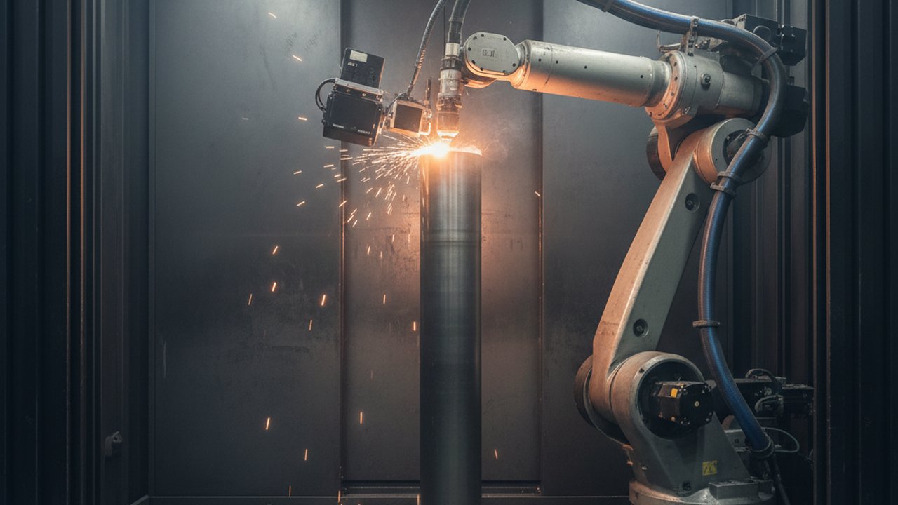
On the sensing side the constraint is physical: the device sits close to a moving torch, inside an enclosure, without adding mass the robot carries through every path. That compact, embedded role is what the HeatCam IR-S thermal camera is designed for.
Frequently Asked Questions
Where should the interlayer temperature setpoint sit relative to the qualified limit?
Below it, by a margin that covers measurement uncertainty and loop latency. The qualified limit is what the procedure allows; the setpoint is what the controller aims at. If the two are the same number, every measurement error and every second of decision delay turns into a genuine excursion in the build record.
Should the control loop read the deposited bead or the substrate?
It should read whatever the qualified procedure defines as the interlayer measurement location, which is normally the previously deposited layer at the point where the next pass will start. Reading a hotter or cooler location than the procedure names produces a loop that controls a number nobody qualified.
What hysteresis band stops a dwell controller from chattering?
A release threshold set below the trigger threshold, wide enough that measurement noise cannot straddle it. Without hysteresis a loop sitting near the setpoint restarts and pauses repeatedly, which fragments the thermal history, distorts the layer time and fills the record with events that mean nothing.
How should a WAAM cell behave if the temperature sensor drops out mid-build?
It should fail to a defined safe state rather than continue on the last known value. Options are a conservative fixed dwell, a hold for operator decision, or a controlled abort. What must never happen is a loop silently treating a stale reading as current and resuming deposition on data that stopped updating.
How do you validate that an interlayer temperature control loop actually works?
By running an instrumented build: calibrated contact thermocouples on the substrate and part, logged against the same clock as the loop, then comparing what the loop measured with what the reference measured at each resume decision. The residual, not the sensor datasheet, is the accuracy of the loop as installed.
Why does an interlayer temperature loop drift over the height of a tall wall?
Because the conduction path to the baseplate lengthens as the wall grows, so each layer sheds heat more slowly than the one below it. A loop tuned on early layers will under-dwell at height. Emissivity also shifts as the surface oxidises, which moves the measured value even when the true temperature is unchanged.
What should a build record contain to make the control loop auditable?
For every layer: the measured interlayer temperature at the resume decision, the timestamp, the layer index, the setpoint in force, and any dwell extension or sensor fault. That set lets a reviewer reconstruct why deposition restarted when it did, which is the question an additive manufacturing audit actually asks.
Close the loop on your WAAM cell
Send us your deposition programme, the qualified interlayer window and the cell layout, and we will map the measurement, the decision path and the record it should leave behind.
Discuss an interlayer control loopTherness solution: Welding camera — Thermal and high-speed imaging that watches the arc, the pool and the cooling seam while the weld is made.
Frequently Asked Questions
Where should the interlayer temperature setpoint sit relative to the qualified limit?
Below it, by a margin that covers measurement uncertainty and loop latency. The qualified limit is what the procedure allows; the setpoint is what the controller aims at. If the two are the same number, every measurement error and every second of decision delay turns into a genuine excursion in the build record.
Should the control loop read the deposited bead or the substrate?
It should read whatever the qualified procedure defines as the interlayer measurement location, which is normally the previously deposited layer at the point where the next pass will start. Reading a hotter or cooler location than the procedure names produces a loop that controls a number nobody qualified.
What hysteresis band stops a dwell controller from chattering?
A release threshold set below the trigger threshold, wide enough that measurement noise cannot straddle it. Without hysteresis a loop sitting near the setpoint restarts and pauses repeatedly, which fragments the thermal history, distorts the layer time and fills the record with events that mean nothing.
How should a WAAM cell behave if the temperature sensor drops out mid-build?
It should fail to a defined safe state rather than continue on the last known value. Options are a conservative fixed dwell, a hold for operator decision, or a controlled abort. What must never happen is a loop silently treating a stale reading as current and resuming deposition on data that stopped updating.
How do you validate that an interlayer temperature control loop actually works?
By running an instrumented build: calibrated contact thermocouples on the substrate and part, logged against the same clock as the loop, then comparing what the loop measured with what the reference measured at each resume decision. The residual, not the sensor datasheet, is the accuracy of the loop as installed.
Why does an interlayer temperature loop drift over the height of a tall wall?
Because the conduction path to the baseplate lengthens as the wall grows, so each layer sheds heat more slowly than the one below it. A loop tuned on early layers will under-dwell at height. Emissivity also shifts as the surface oxidises, which moves the measured value even when the true temperature is unchanged.
What should a build record contain to make the control loop auditable?
For every layer: the measured interlayer temperature at the resume decision, the timestamp, the layer index, the setpoint in force, and any dwell extension or sensor fault. That set lets a reviewer reconstruct why deposition restarted when it did, which is the question an additive manufacturing audit actually asks.