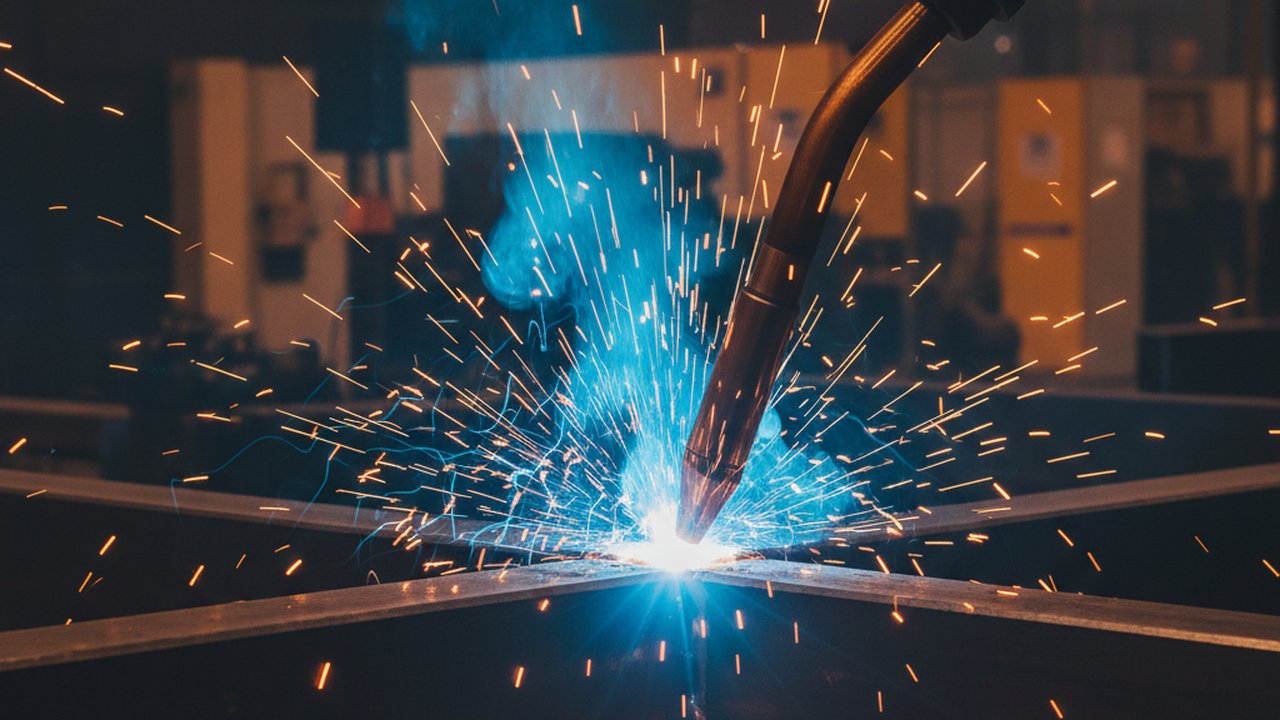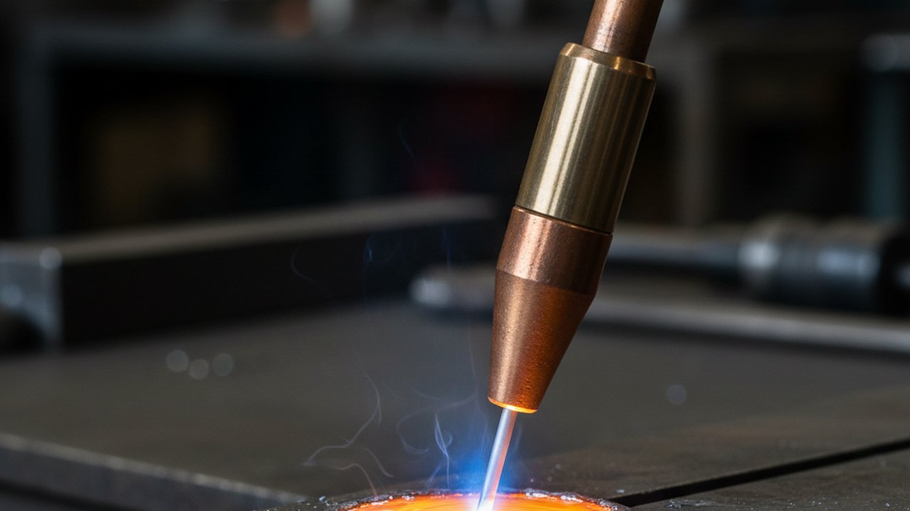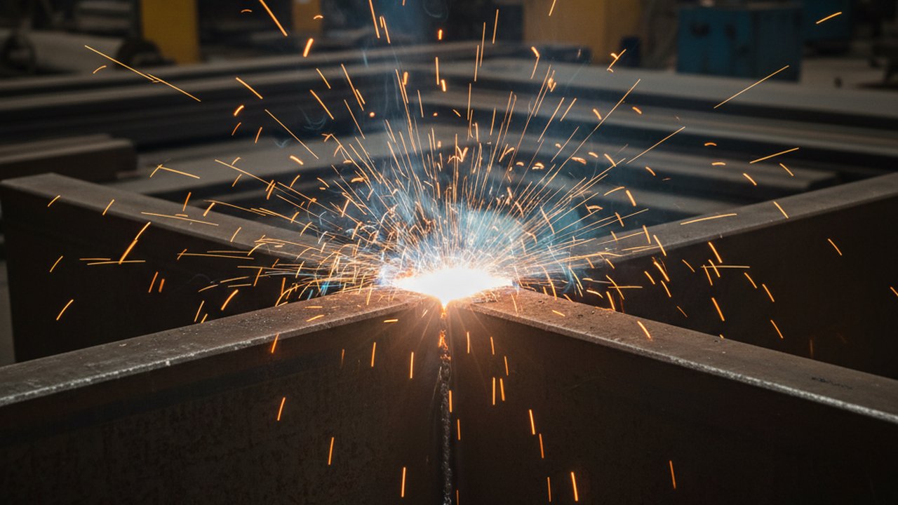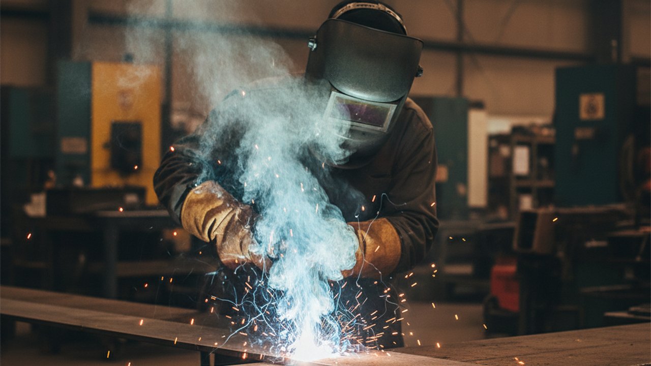
Weld fume plume shape and brightness change the instant arc stability changes, which makes the plume one of the earliest visible signals a real-time monitoring system can read — well before the bead has finished cooling, and often before pool geometry itself shows anything wrong. A steady, well-shaped plume marks a stable process; a turbulent, dense, or unusually bright plume is the arc reporting a disturbance in shielding gas, contamination, or process stability.
This article covers the physics behind why the plume behaves this way, what specific shape and brightness changes correlate with which underlying problem, how vision-based monitoring turns that into a usable process signal, and where the failure modes are when relying on plume data alone.
Key takeaways
- Welding fume is metal vapour that condenses into fine oxide particles almost instantly on contact with cooler air, so plume formation tracks the arc’s vaporisation rate in real time.
- A stable arc under a clean, steady shielding gas flow produces a consistent, upright plume; disturbing either input visibly changes plume shape within a fraction of a second.
- Increased turbulence or density typically signals air ingress from a draught or a failing gas shield — the same disruption that raises porosity risk at the weld pool.
- A sudden brightness flare combined with visible spatter through the plume typically signals surface contamination reacting in the arc.
- The plume is an early, low-resolution signal on its own; it becomes a reliable defect precursor only when fused with pool geometry, arc position and thermal data.
- Vision-based plume monitoring can flag a suspect weld segment for targeted inspection while production continues, rather than waiting for end-of-line NDT.
What the video shows
The clip below shows the plume rising off a live weld pool as the arc burns, visibly responding to the process as it runs.

Watch how the plume holds a steady, upright shape while the arc is stable, and notice how quickly that shape would change if shielding gas coverage, arc length, or surface cleanliness shifted. That responsiveness is exactly what makes the plume useful as a monitoring input: it is reacting to the same instability that, left unaddressed, produces porosity or lack of fusion at the pool.
The physics: from metal vapour to visible plume
Welding fume originates as metal vapour boiled off the arc column and the surface of the molten pool. As that vapour meets cooler surrounding air, it condenses almost instantly into fine metal oxide particles, forming the visible cloud rising off the weld. This is not a random byproduct: the rate of vaporisation and the gas flow pattern around the arc are both steady when the process is steady, so a healthy, stable arc under clean shielding gas produces a plume of consistent shape and density.
Disturb either input and the plume changes measurably:
Air ingress and shielding gas loss
A draught reaching the weld zone, or a shielding gas flow that is dropping below its effective coverage rate, lets ambient air reach the arc. The additional oxygen oxidises more of the vaporised metal, producing a denser, more turbulent plume. This is the same air ingress that raises porosity risk at the pool surface, so a plume that has visibly thickened or become turbulent is often an earlier warning of the same root cause a post-weld radiograph would later reveal as porosity.
Contamination and surface condition
Oil, rust, moisture, or coating residue on the base material reacts in the arc and typically flares plume brightness while adding visible spatter launching through the cloud. Because contamination-driven instability tends to be localized to the contaminated region rather than continuous along the seam, a brightness spike that appears and clears within a short segment is a useful marker for where to focus inspection.
Transfer mode and current waveform
Short-circuit and spray transfer in GMAW produce visibly different plume dynamics because the arc’s on/off cycling and droplet detachment pattern differ. A monitoring system trained on a specific process needs its baseline established for that transfer mode, since what looks like “turbulence” in one mode may be the normal signature of another.
The plume forms before the bead solidifies, which is exactly why it is one of the earliest observable process signals available — but it is also low-resolution on its own. A thickened plume tells you something changed; it does not by itself tell you whether the result was a sound weld or a rejectable one.
Reading plume signals: a decision guide
| Observed plume behaviour | Likely cause | Typical companion signal | Suggested response |
|---|---|---|---|
| Steady, upright, consistent density | Stable arc, adequate shielding | Consistent pool geometry | None — this is the baseline |
| Denser, more turbulent, wider spread | Draught or failing shielding gas coverage | Pool surface disturbance, possible porosity risk | Check gas flow and nozzle standoff; flag segment for inspection |
| Sudden brightness flare with spatter | Surface contamination (oil, rust, moisture) | Localized spatter burst | Flag the localized segment; verify base material cleaning |
| Erratic pulsing out of sync with the process | Arc length instability or wire feed irregularity | Arc voltage or current fluctuation | Cross-check with arc sensor data before acting |
| Plume abruptly interrupted or absent | Arc extinguished or severe disruption | Loss of pool signal | Immediate stop condition — treat as a process fault, not a plume anomaly alone |
Failure modes and fixes
| Failure mode | Symptom | Root cause | Fix |
|---|---|---|---|
| False positives on normal transfer noise | Frequent flags with no confirmed defect | Baseline not tuned to the actual transfer mode | Re-baseline plume classifier per process and transfer mode before production use |
| Missed contamination events | Defect found downstream, no plume flag logged | Camera field of view too narrow or frame rate too low to catch a brief flare | Widen field of view and confirm frame rate against the shortest expected event duration |
| Plume signal swamped by ambient shop lighting or extraction airflow | Noisy, inconsistent readings | Uncontrolled ambient light or extraction draught disturbing the plume itself | Standardize local lighting; verify extraction placement does not itself distort plume shape |
| Over-reliance on plume alone | Alerts without corroborating evidence, low trust in the system | Plume used as a standalone trigger instead of one fused input | Fuse plume signal with pool and thermal data before triggering an action |
Verification: confirming a plume signal predicts a real defect
Before trusting plume-based flags in production, validate the correlation rather than assuming it:
- Correlate flagged segments with post-weld NDT results on a representative sample run, checking whether plume-flagged segments actually show elevated porosity or other imperfections under radiographic or visual inspection per ISO 5817 acceptance criteria.
- Establish a baseline per process and transfer mode, since normal plume dynamics differ between short-circuit GMAW, spray transfer, and TIG, and a classifier tuned on one will misfire on another.
- Test deliberately induced disturbances — a controlled shielding gas interruption or a contaminated coupon — and confirm the plume signal responds as expected before relying on it for uncontrolled production faults.
- Re-validate after any change to camera position, lighting, or extraction setup, since all three can alter the observed plume without any change to actual process stability.
Step-by-step: adding plume monitoring to a vision-based system
- Define the region of interest above the weld pool where the plume is consistently visible without being obscured by the torch or fixture.
- Establish per-process baselines for plume density, shape, and brightness under known-good conditions for each transfer mode and material in use.
- Fuse the plume channel with pool geometry, arc position, and thermal data rather than treating it as an independent trigger.
- Run the deliberate-disturbance validation described above before go-live.
- Set the response action: a flagged segment for targeted inspection, not an automatic reject, unless corroborating evidence from other channels supports a harder stop.
- Log every flagged event with a timestamp and weld position so the record ties back to the specific segment for later NDT correlation.
- Review flagged-versus-confirmed-defect rates periodically and retune the baseline as process conditions, materials, or equipment change.
Where this fits in weld quality monitoring
Vision and thermal streams fused into one weld record is the core idea behind a modern welding monitoring system: the plume is one more channel alongside pool geometry, arc position, and thermal signature that a classifier weighs to judge weld quality in real time, as introduced in weld quality monitoring 101. The imperfections a disturbed plume often precedes — porosity, lack of fusion — are classified under ISO 6520-1, and their acceptance limits by quality level are set in ISO 5817. Where a monitoring installation is cited as process-monitoring evidence, ISO 3834-2 is the relevant quality-system reference, and it treats in-process monitoring as a complement to post-weld inspection rather than a replacement for it.
The underlying vaporisation and condensation physics sit under general references for welding fume formation and shielding gas function. Occupational exposure guidance for welding fume is published by NIOSH, and the American Welding Society publishes technical resources on process stability and porosity mechanisms. Broader machine-vision context for real-time process monitoring is documented under machine vision fundamentals.
Related videos and products
- Reading the weld fume plume — the source clip for this article.
- When a weld goes wrong — the visual signature of a failing weld across multiple channels.
- Real-time molten pool and arc detection — the pool-geometry channel the plume signal is fused with.
- HeatCore AI product page — the software that fuses vision and thermal signals.
- Welding monitoring system overview — how the plume channel fits the broader real-time quality picture.
FAQ
Why does a stable welding arc produce a different fume plume than an unstable one?
Fume forms from metal vapour condensing into oxide particles the instant it leaves the arc. A stable arc vaporises metal and holds shielding gas flow at a steady rate, so the plume rises as a consistent, upright column. Disturb either the arc or the gas shield and the plume’s shape reports it within a fraction of a second.
What does a denser or more turbulent weld fume plume usually indicate?
A denser, more turbulent plume usually means more air has reached the arc, either from a draught or from a failing shielding gas flow. The extra oxygen oxidises more metal vapour, thickening the visible plume and often coinciding with porosity risk from disrupted shielding at the weld pool.
Can welding fume plume analysis detect a defect before the weld cools?
On its own the plume is an early hint, not a verdict. Because it forms the instant metal vaporises, a plume signature can flag a suspect segment before the bead solidifies, but it is combined with pool geometry, arc position and thermal data to separate a genuine defect precursor from a harmless visual variation.
Does a bright flare in the fume plume always mean contamination?
A sudden brightness increase combined with visible spatter launching through the plume commonly indicates surface contamination such as oil, rust or moisture reacting in the arc. It is a strong but not exclusive signal, which is why plume brightness is weighted alongside other monitored channels rather than used as a standalone pass or fail trigger.
What causes shielding gas loss to change the fume plume before other symptoms appear?
Shielding gas loss lets ambient air reach the arc column before it visibly affects the weld pool surface, so the plume’s density and turbulence often shift a few frames earlier than pool geometry does. A vision system watching both channels can flag the gas-loss signature slightly ahead of the pool-level evidence.
Why is welding fume plume monitoring combined with thermal and pool imaging rather than used alone?
The plume is one weighted input, not a complete diagnosis. Pool geometry shows penetration and fusion directly, and thermal data captures the cooling curve, while the plume adds an earlier, lower-resolution instability signal. Fusing all three gives a classifier more evidence than any single channel provides on its own.
Can weld fume plume video be used as process monitoring evidence for ISO 3834?
Timestamped video that demonstrably captures process behaviour relevant to the WPS, such as arc stability indicators, can form part of the electronic process record ISO 3834-2 calls for. It complements, rather than replaces, the post-weld inspection and NDT evidence that establishes final acceptance.
Read the plume alongside pool and thermal data
See how HeatCore AI fuses vision and thermal streams into one real-time weld quality signal, with every flagged event logged for traceability.
Book a demoTherness solution: Welding camera — Thermal and high-speed imaging that watches the arc, the pool and the cooling seam while the weld is made.
Frequently Asked Questions
Why does a stable welding arc produce a different fume plume than an unstable one?
Fume forms from metal vapour condensing into oxide particles the instant it leaves the arc. A stable arc under a steady gas shield rises as a consistent, upright column. Disturb either the arc or the gas shield and the plume's shape reports it within a fraction of a second.
What does a denser or more turbulent weld fume plume usually indicate?
A denser, more turbulent plume usually means more air has reached the arc, either from a draught or from a failing shielding gas flow. The extra oxygen oxidises more metal vapour, thickening the visible plume and often coinciding with porosity risk from disrupted shielding at the weld pool.
Can welding fume plume analysis detect a defect before the weld cools?
On its own the plume is an early hint, not a verdict. Because it forms the instant metal vaporises, a plume signature can flag a suspect segment before the bead solidifies, but it is combined with pool geometry, arc position and thermal data to separate a genuine defect precursor from a harmless visual variation.
Does a bright flare in the fume plume always mean contamination?
A sudden brightness increase with visible spatter launching through the plume commonly indicates surface contamination such as oil, rust or moisture. It is a strong but not exclusive signal, which is why brightness is weighted alongside other monitored channels rather than used as a standalone trigger.
What causes shielding gas loss to change the fume plume before other symptoms appear?
Shielding gas loss lets ambient air reach the arc column before it visibly affects the weld pool surface, so the plume's density and turbulence often shift a few frames earlier than pool geometry does. A vision system watching both channels can flag the gas-loss signature slightly ahead of the pool-level evidence.
Why is welding fume plume monitoring combined with thermal and pool imaging rather than used alone?
The plume is one weighted input, not a complete diagnosis. Pool geometry shows penetration and fusion directly, thermal data captures the cooling curve, and the plume adds an earlier, lower-resolution instability signal. Fusing the three gives a classifier more evidence than any one channel alone.
Can weld fume plume video be used as process monitoring evidence for ISO 3834?
Timestamped video that demonstrably captures process behaviour relevant to the WPS, such as arc stability indicators, can form part of the electronic process record ISO 3834-2 calls for. It complements, rather than replaces, the post-weld inspection and NDT evidence that establishes final acceptance.
Related Video