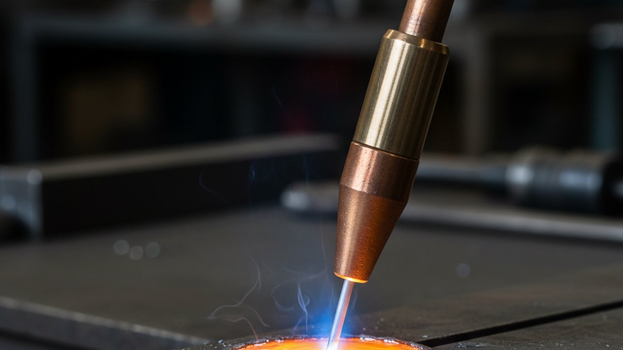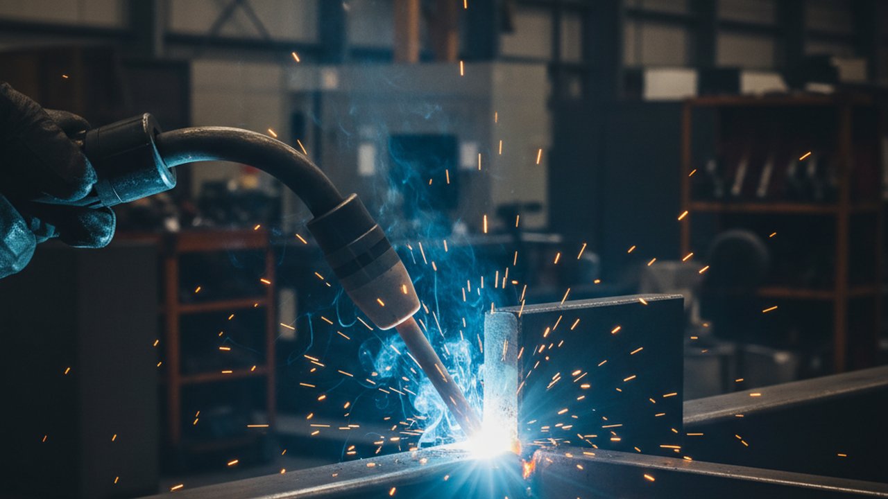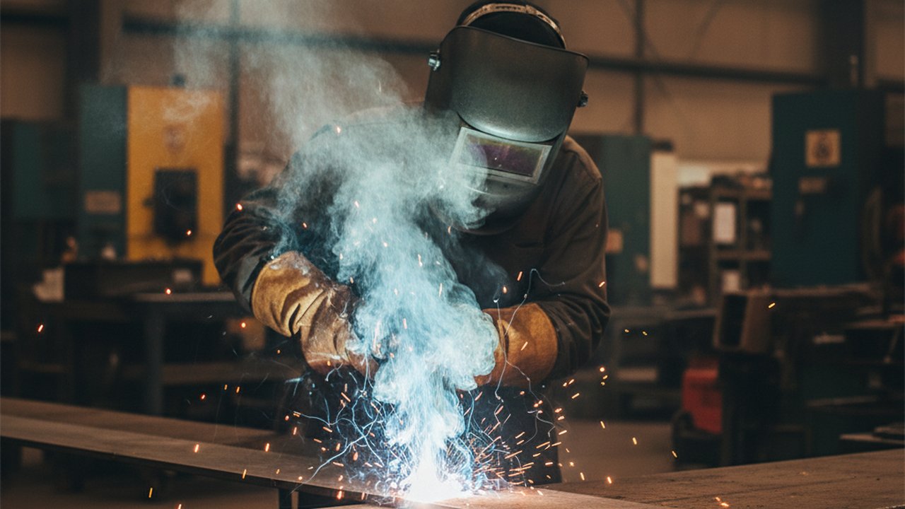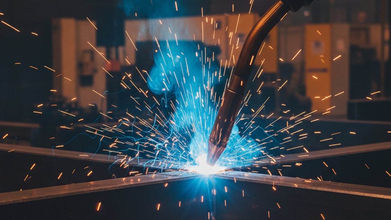
CMT welding droplet transfer instability is easy to miss until it has already cost a part: a bead that narrows for two centimetres, a spray of spatter no one saw happen, a lack-of-fusion call at final inspection with no obvious cause in the weld log. Cold Metal Transfer (CMT) is prized precisely because its droplet transfer is normally so regular — one droplet per dip, at an even beat, with almost none of the arc-force spatter that standard short-circuit GMAW produces. When that regularity breaks, the process has quietly stopped behaving like CMT while the power source keeps reporting a normal weld.
The 480 fps footage of a CMT arc in the video library makes the healthy version of this cycle directly visible: a droplet forms, the wire dips into the pool, the short clears, and the arc re-establishes before the next dip. This article is about the other case — what makes that rhythm break, what the break looks like on camera, what it does to the weld, and how to get it back under control and prove it stayed there.
Key takeaways
- CMT droplet transfer instability is a mechanical and electrical control-loop problem, not a random one — it almost always traces back to stick-out, gas, torch geometry, or a parameter drift outside the qualified window.
- A welding power source alarms on gross faults, not on a cycle that is merely irregular but still completing, so instability commonly produces zero fault code.
- At 480 fps a CMT cycle spans roughly 4 to 10 frames, enough to see dip, retract, arc re-ignition, and droplet detachment as separate events rather than a blur.
- The downstream defects differ by failure mode: some instability throws visible spatter immediately, some produces a cold lap or bead-width swing with no spatter at all.
- Fixing the cause is usually a maintenance action — contact tip, gas path, torch angle — not a WPS rewrite, unless the fix itself changes a WPS-specified parameter.
- Verification means re-running the same joint that showed the fault and comparing new footage or waveform data against a known-good baseline, not trusting one clean-looking pass.
- ISO 6520-1 gives the shared vocabulary for the imperfections this produces; ISO 17637 and AWS D1.1 govern how those imperfections are recorded and judged.
How the CMT cycle actually keeps droplet transfer regular
Cold Metal Transfer earns its name from how little heat and force go into detaching each droplet — low enough that it shows up directly in the heat input calculator compared with standard short-circuit transfer — and that comes from a control loop most GMAW variants do not have.
The arc phase and the controlled short circuit
A CMT cycle alternates two phases at high frequency. During the arc phase, the wire melts and a droplet grows at the tip in the normal GMAW way. Rather than letting arc force or gravity separate that droplet, the process drives the wire forward until it touches the pool, deliberately creating a short circuit. The moment the short is detected, current is cut sharply, which is what keeps the process cool and largely spatter-free compared with standard short-circuit transfer.
Wire-feed reversal is what actually pinches the droplet off
The distinguishing mechanism is that the wire is then mechanically retracted — reversed — at the instant of the short, and it is this retraction, not current, that supplies the force that separates the droplet from the pool. The arc re-establishes at a controlled, low energy level, and the wire feed reverses again to begin the next dip. Every part of that sequence — dip timing, short duration, retract speed, arc re-ignition timing — is closed-loop controlled from the voltage and current signal at the torch. When any of those signals arrives distorted or late, the loop still executes a cycle, but the cycle it executes is no longer the clean one the process was tuned to produce.
What a stable cycle looks like at 480 fps, and what breaks it

The rhythm marker to watch
The single clearest signal in high-speed CMT footage is the beat: exactly one droplet detaching per dip-and-retract cycle, at an interval that does not visibly vary from one cycle to the next. That regularity is what keeps heat input, pool volume, and bead cross-section constant along the joint. It is also the first thing to visibly change when something upstream of the arc has drifted, well before it shows up as a measurable defect in the finished part.
Reading instability against a known-good baseline
An unstable cycle rarely looks dramatic in isolation — it looks like a small deviation from the rhythm you have already established as normal for that wire, gas, and joint. The recognizable failure patterns are a droplet that clings and keeps growing before it finally separates late and unevenly, two dip cycles that merge into what should have been one, a short circuit that clears slowly enough to show visible arcing at the moment of clearance instead of a clean cutoff, and a beat that speeds up and slows down across the length of the weld rather than holding steady. None of these require a trained eye to see once the footage is paused frame by frame next to a clip of the same joint running correctly — the comparison is the diagnostic.
None of these deviations trip a power-source fault. The source sees a completed cycle either way — the arc struck, the short cleared, the wire kept feeding. The information that the cycle was irregular exists only in the visual or electrical waveform record, which is exactly why a monitoring system that captures one of those records catches problems a weld log alone will not.
What actually causes droplet transfer to destabilize
Instability in a mechanically controlled process like CMT is rarely mysterious once you separate the candidate causes by what they change.
Contact tip and wire path wear
A worn or oversized contact tip lets the wire wander off-axis inside the tip bore, which changes the effective stick-out and the angle at which the wire approaches the pool from cycle to cycle. Because the retract-and-dip geometry is exactly what the CMT loop is timed against, even a small amount of wire wander is enough to make some cycles dip early and some late.
Shielding gas composition and flow drift
Shielding gas affects arc stability and surface tension at the droplet, and a flow that has drifted low, a leak in the hose, or a regulator delivering the wrong blend all change how cleanly the arc re-establishes after the short clears. A gas problem often shows up first as an intermittent flicker in the arc phase rather than in the dip itself, which is a useful diagnostic distinction on camera.
Torch angle and stick-out drift
On a robotic cell, fixture wear, a bumped torch bracket, or a part that is not seated the way it was during programming all change the real stick-out and travel angle away from what the program assumes. Manual welding has the same failure mode without the robot: operator fatigue changes hand position and travel angle over the course of a shift.
Parameters drifted outside the qualified window
Wire feed speed, voltage trim, and dynamic correction settings on the power source interact with material thickness and joint fit-up. A parameter set that was qualified for one fit-up condition and is now running against a wider or narrower gap than it was proven on is a common, easily overlooked source of instability that has nothing wrong with the equipment at all.
The defects unstable droplet transfer actually seeds
Which defect shows up depends on which part of the cycle broke, which is why a single “spatter count” post-weld check misses some of the cases that matter most.
Spatter and nozzle fouling
A short that clears slowly, or a droplet that separates unevenly under residual force, throws molten metal outward. Beyond the part itself, spatter builds up inside the gas nozzle, which then progressively disrupts shielding gas coverage — a self-reinforcing failure that gets worse the longer it runs unaddressed. The causes, prevention, and acceptance side of spatter itself is covered in weld spatter causes, prevention, and acceptance criteria.
Cold lap and incomplete fusion
Not every instability produces spatter. A short that clears cleanly but at the wrong point in the retract cycle can deposit a droplet with too little heat behind it to fuse properly to the base metal or the previous pass, producing a cold lap — a defect that is invisible on the surface and shows up only at NDT or in service. This is the category ISO 6520-1 classifies as incomplete fusion, and it is the reason visual inspection alone is not a complete verification strategy for this kind of instability.
Bead width and reinforcement variation
A beat that drifts in frequency changes how much metal is deposited per unit length even when travel speed is held constant, producing a bead that visibly narrows, widens, or changes crown height along the joint — often the first symptom a downstream inspector notices, well after the cause has already come and gone.
Failure modes and fixes
| Symptom on camera | Most likely cause | Corrective action |
|---|---|---|
| Droplet clings and grows before separating late | Worn contact tip changing wire angle or stick-out | Replace contact tip; verify stick-out against the WPS-specified value |
| Two dip cycles merge into one | Stick-out too long, or fit-up gap wider than qualified | Restore programmed stick-out; check fit-up against the qualification range |
| Visible arcing at short clearance instead of a clean cutoff | Shielding gas flow low, contaminated, or wrong blend | Check regulator, hose integrity, and flow rate; verify against the gas classification for the process |
| Beat speeds up and slows down along the weld | Torch angle or fixture drift, or operator fatigue on manual work | Recheck fixture and torch mounting; on manual work, schedule a break or rotate operators |
| Instability appears only at the start or end of the weld | Arc start/end parameter set separate from steady-state, or wire burn-back setting | Review start/end parameter block on the power source independently of the main weld schedule |
| Instability appears only on one joint configuration, not others | Parameter set qualified for a different fit-up than currently running | Re-verify fit-up against the qualified range before adjusting the WPS itself |
Verifying that transfer is actually back under control
A fix is not verified until it is checked against the exact condition that exposed the fault, using a record that can actually show the cycle rather than only its aftermath.
- Re-run the same joint, wire, and travel speed that produced the instability. A different joint configuration proves nothing about whether the original condition is resolved.
- Capture new high-speed footage or waveform data across the full length of the re-run weld, not a short sample — intermittent instability can appear only partway through a pass.
- Compare cycle-by-cycle against a known-good baseline clip, frame by frame, rather than judging the new footage in isolation. What “normal” looks like for this exact wire and gas combination is the only useful reference.
- Cross-check against parametric data where it is available — wire feed speed, voltage, and current recorded alongside the video gives an independent signal that should move in step with what the footage shows.
- Record the result against the weld identifier, not just in a maintenance log, so the fix is traceable to the specific weld, operator, and production order it applied to under ISO 17637 visual-testing documentation practice.
- Only escalate to a WPS review if the fix required changing a parameter the WPS specifies — most contact tip, gas, and fixture fixes do not.
Step-by-step: setting up 480 fps monitoring for CMT transfer stability
- Mount the camera torch-side, close enough to resolve individual droplets but outside the spatter zone, matching the geometry the PoolDrop camera uses in the reference footage.
- Filter or suppress arc glare so the sensor is not saturated during the arc phase — without this step the dip and retract are visible but the arc re-ignition is a blown-out white frame.
- Record a baseline set of known-good cycles for each wire, gas, and joint combination actually run in production, before relying on the system to flag deviations.
- Set a cycle-regularity check, not just a spatter-event trigger, since some of the defects above never throw visible spatter.
- Correlate the visual record with electrical waveform data — WeldTrace or an equivalent parametric acquisition system — so a flagged event can be checked two ways before it is acted on.
- Tie the record to the weld identifier and WPS reference so a flagged cycle can be traced back to operator, fixture, and production order during root-cause review.
- Review flagged cycles on a fixed cadence, not only after a defect is already found downstream — the value of the footage is catching the cause before it reaches a part.
FAQ
Why does CMT welding droplet transfer become unstable?
Instability usually traces to something changing the wire’s dip-and-retract geometry: contact tip wear altering stick-out, shielding gas drift, torch angle change, or parameters drifted outside the WPS-qualified window. The control loop then reads the arc voltage signal late or wrong.
What does unstable droplet transfer look like on high-speed video?
A stable CMT cycle shows one droplet detaching cleanly per dip, at an even beat. Instability shows a droplet that clings and grows before separating, two cycles merging into one, a short circuit that clears slowly with visible arcing at clearance, or a beat that speeds up and slows down across the weld.
Can droplet transfer instability happen without an alarm on the welding power source?
Yes. A power source alarms on gross faults like wire stick or loss of arc, not on a cycle that is merely irregular but still completing. Irregular transfer within the source’s normal operating range produces no fault code, which is why visual or waveform monitoring catches it and a power-source log alone does not.
How fast does a camera need to run to see CMT droplet transfer clearly?
CMT cycles typically run on the order of 50 to 120 Hz depending on wire feed speed and material, so each cycle lasts single-digit milliseconds. A camera at 480 fps captures roughly 4 to 10 frames per cycle, enough to resolve dip, retract, arc re-ignition and droplet detachment as separate visible events.
Does unstable droplet transfer always produce visible spatter?
No. Some instability produces spatter immediately, but some shows up first as inconsistent bead width or an intermittent cold lap with no spatter at all, since the short clears cleanly but at the wrong moment in the retract cycle. A visual or waveform record catches this; spatter counting alone does not.
What is the difference between CMT and standard short-circuit GMAW transfer?
Standard short-circuit GMAW relies on current alone to pinch off the droplet when the wire shorts to the pool — comparatively energetic. CMT adds a mechanically controlled wire retract synchronized to the short, so the droplet separates with near-zero current — the reason CMT runs cooler and sprays less.
Can droplet transfer instability be fixed without changing the WPS?
Often yes. Contact tip replacement, restoring correct stick-out and torch angle, and correcting shielding gas flow or a leak all restore stability within the qualified parameter window and require no WPS change. A fix only needs requalification when it changes a parameter the WPS actually specifies.
How do you verify a droplet transfer fix actually worked?
Re-run the same joint and travel speed that showed the problem, capture new high-speed footage or waveform data, and compare cycle regularity frame by frame or trace by trace against a known-good baseline — not against a single clean-looking weld, since one good pass does not rule out an intermittent fault.
For the visual-testing side of what this footage documents, see the broader 480 fps weld pool camera visualisation guide. For frame-rate selection generally, the welding camera overview and the welding parameter monitoring hub cover the equipment side more broadly.
Beyond the standards already covered above, AWS D1.1 sets the workmanship and visual-acceptance framework structural GMAW and CMT welds are ultimately judged against; spatter removal itself is driven by the contract and the application rather than a blanket clause. For general background on weld quality control, TWI’s technical knowledge library and its job knowledge series cover the operator and defect-control side, ASM International covers materials-side context, NIST’s manufacturing program covers measurement-science background, OSHA covers the operator-safety side of arc processes, and the Journal of Materials Processing Technology carries peer-reviewed research on GMAW droplet transfer physics.
See droplet transfer stability on your own welds
PoolDrop camera captures the same 480 fps footage on your production cell, so instability shows up on camera before it shows up as a defect.
Talk to us about PoolDropTherness solution: Welding camera — Thermal and high-speed imaging that watches the arc, the pool and the cooling seam while the weld is made.
Frequently Asked Questions
Why does CMT welding droplet transfer become unstable?
Instability usually traces to something changing the wire's dip-and-retract geometry: contact tip wear altering stick-out, shielding gas drift, torch angle change, or parameters drifted outside the WPS-qualified window. The control loop then reads the arc voltage signal late or wrong.
What does unstable droplet transfer look like on high-speed video?
A stable CMT cycle shows one droplet detaching cleanly per dip, at an even beat. Instability shows a droplet that clings and grows before separating, two cycles merging into one, a short circuit that clears slowly with visible arcing at clearance, or a beat that speeds up and slows down across the weld.
Can droplet transfer instability happen without an alarm on the welding power source?
Yes. A power source alarms on gross faults like wire stick or loss of arc, not on a cycle that is merely irregular but still completing. Irregular transfer within the source's normal operating range produces no fault code, which is why visual or waveform monitoring catches it and a power-source log alone does not.
How fast does a camera need to run to see CMT droplet transfer clearly?
CMT cycles typically run on the order of 50 to 120 Hz depending on wire feed speed and material, so each cycle lasts single-digit milliseconds. A camera at 480 fps captures roughly 4 to 10 frames per cycle, enough to resolve dip, retract, arc re-ignition and droplet detachment as separate visible events.
Does unstable droplet transfer always produce visible spatter?
No. Some instability produces spatter immediately, but some shows up first as inconsistent bead width or an intermittent cold lap with no spatter at all, since the short clears cleanly but at the wrong moment in the retract cycle. A visual or waveform record catches this; spatter counting alone does not.
What is the difference between CMT and standard short-circuit GMAW transfer?
Standard short-circuit GMAW relies on current alone to pinch off the droplet when the wire shorts to the pool — comparatively energetic. CMT adds a mechanically controlled wire retract synchronized to the short, so the droplet separates with near-zero current — the reason CMT runs cooler and sprays less.
Can droplet transfer instability be fixed without changing the WPS?
Often yes. Contact tip replacement, restoring correct stick-out and torch angle, and correcting shielding gas flow or a leak all restore stability within the qualified parameter window and require no WPS change. A fix only needs requalification when it changes a parameter the WPS actually specifies.
How do you verify a droplet transfer fix actually worked?
Re-run the same joint and travel speed that showed the problem, capture new high-speed footage or waveform data, and compare cycle regularity frame by frame or trace by trace against a known-good baseline — not against a single clean-looking weld, since one good pass does not rule out an intermittent fault.
Related Video