T8/5 cooling time measured once on a procedure qualification coupon becomes a number that every subsequent production weld is silently assumed to match. That assumption is convenient and, on a real shop floor, frequently wrong. Interpass temperature drifts across a shift, a fixture behaves as a heat sink on some parts and not others, and a shielding-gas issue nobody notices changes the arc’s heat delivery — none of which show up in a WPS revision.
This article is about why the qualification-coupon assumption breaks down in production, what actually changes the cooling curve on the shop floor, and how measuring T8/5 (and the related T12/7 window) on every weld — rather than once, on paper — turns a metallurgical estimate into a verified, per-part quality record.
Key takeaways
- A PQR coupon establishes that a WPS can produce an acceptable cooling curve under controlled conditions. It does not prove that every later production weld actually did.
- Interpass temperature drift, fixture heat-sink effects, ambient shop temperature, and operator variation all shift the real cooling curve without appearing anywhere in the WPS.
- T8/5 (800 to 500 degrees C) governs transformation behaviour in carbon and low-alloy steels; some WPS documents for stainless, duplex or other alloy procedures specify T12/7 (1200 to 700 degrees C) or another interval instead.
- A calibrated thermal imaging system can track the cooling bead directly, producing a measured curve for the actual part instead of an estimate from nominal parameters.
- Per-weld measurement does not replace destructive PQR testing; it is an additive, continuous control that confirms the qualified window is held in production.
- Out-of-range cooling events should generate an immediate, logged alert, and can be wired to a PLC or robot controller to pause the sequence before a suspect weld continues down the line.
- A timestamped, per-weld cooling record is direct evidence for ISO 3834-2’s monitoring requirement and forms part of the traceable weld record for the finished part.
What the video shows
The clip below shows a thermal-imaging system tracking the cooling bead of a live weld and computing the T8/5 interval automatically, frame by frame, as the joint cools. The same region-of-interest tracking is configurable for T12/7 or any other custom temperature window a procedure calls for.
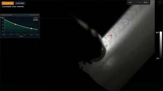
Two things are worth noticing in the footage. First, the measurement runs on the production part itself, in its real fixture, at whatever interpass temperature the part actually carries at that moment — not on a qualification coupon welded once, in isolation, weeks earlier. Second, because the whole region of interest is tracked rather than a single point, the system also sees where along the bead the cooling deviates, which is exactly the kind of localized anomaly — a draft, an unplanned heat-sink contact, a locally low interpass reading — that a single thermocouple placement would never catch.
The assumption behind a PQR-only cooling time
Procedure qualification exists to prove that a documented set of parameters — process, consumables, joint geometry, preheat and interpass limits, heat input range — produces a weld with acceptable mechanical properties. Part of that proof, for the steels where transformation behaviour matters, is a cooling curve captured with a thermocouple close to the fusion boundary on the qualification coupon. Once that PQR is approved, the WPS derived from it becomes the standing instruction for every production weld made under it.
Why that number stops representing reality
The PQR coupon is welded once, on a bench or a simple fixture, under conditions a welding engineer deliberately controls. Production welding runs under conditions nobody controls to the same degree, repeated thousands of times:
- Interpass temperature drift across a multi-pass sequence, with dwell time between passes rarely matching the coupon.
- Fixture thermal mass that conducts heat away from the joint differently than the qualification setup, and differently part to part.
- Ambient shop temperature swinging between a summer and winter shift while the WPS itself never changes.
- Operator and equipment variation in travel speed, torch angle and gas coverage shifting the instantaneous heat input.
None of these are WPS violations on paper, yet each can move the real cooling curve outside the window the PQR proved acceptable. ISO 15614-1:2017 establishes that a procedure can work; it says nothing about whether the ten-thousandth weld made under it actually did.
A PQR coupon answers “can this procedure produce an acceptable weld?” It cannot answer “did this specific production weld cool the way the PQR weld did?” Those are different questions, and only the second one is what actually protects the part in service.
T8/5 and T12/7: which window, and why it changes by material
T8/5 — the time spent between 800 degrees C and 500 degrees C — is the standard reference window for carbon and low-alloy structural and pressure-equipment steels because that is where austenite decomposes into the microstructures that decide the joint’s toughness and crack susceptibility. Cool too fast through that window and the heat-affected zone can form hard, crack-prone martensite; cool too slowly and grain coarsening can erode toughness.
Not every alloy system transforms in the same temperature band, and not every WPS specifies T8/5. Some stainless, duplex, or proprietary alloy procedures call for a different interval — such as T12/7 (1200 to 700 degrees C) — because the transformation behaviour that matters for that material sits at a different temperature range. Which window applies is set by the qualified procedure, not by alloy family. A monitoring system that can track any user-defined interval, not just a fixed T8/5 window, is what lets a shop run a mixed-material floor under whatever window each procedure specifies.
A decision checklist for choosing and verifying the window
- The window (T8/5, T12/7, or custom) is stated explicitly in the WPS, not left implicit.
- The window matches the transformation range for the base material and filler being welded.
- The measurement location is fixed and identical between PQR and production.
- Calibration and emissivity settings match the surface condition expected in production, not a ground coupon.
- The acceptance range is a band around the PQR value, not a single point.
- Out-of-range events are logged with a timestamp and part identifier.
- The alert response (hold, flag, requalify) is agreed with quality before go-live.
How optical cooling-time measurement actually works
A non-contact system builds a cooling-time record one of two ways, depending on camera geometry. With a fixed viewpoint — a stationary robotic-cell camera, or a part held in one fixture position through cooling — the system tracks a region of interest on the bead and reads its apparent temperature directly over time, and the crossings through 800 and 500 degrees C give T8/5 with no conversion needed. With a torch-referenced geometry, where the sensor travels with the torch and watches the bead trailing behind it, the system instead measures how far behind the arc a given isotherm sits and converts that distance to elapsed time using the known travel speed. Both approaches depend on correct emissivity handling as the surface oxidises through the interval, and on keeping the arc’s own glare out of the measurement region — a sensor pointed too close to an active arc saturates rather than measures.
Verification: proving the measured value means something
A cooling-time reading is only as trustworthy as its calibration chain. Before relying on it for production decisions:
- Bench the camera against thermocouples on a representative coupon, comparing full curve shape rather than only the two crossing times — agreement on the interval with disagreement in shape usually means coincidence, not accuracy.
- Re-validate whenever material, filler or surface condition changes. Emissivity shifts with surface finish and oxide state, so a calibration for clean carbon steel does not transfer to a scaled or coated surface.
- Set the acceptance band with the responsible welding engineer, using the PQR result as the reference point and a documented tolerance around it, not a bare pass/fail on one number.
- Re-verify after any fixture, camera, or lens change, since a shifted field of view can silently change which part of the bead is read.
Failure modes and fixes
| Failure mode | Symptom | Root cause | Fix |
|---|---|---|---|
| Curve looks plausible but disagrees with thermocouple | Interval matches, shape does not | Emissivity assumption wrong for the actual surface | Re-calibrate emissivity against the real production surface, not a bench sample |
| Erratic readings near weld start | Spikes or dropouts in the first frames | Arc glare and reflection contaminating the region of interest | Move the region of interest outside the direct arc field of view; discard ignition frames |
| Readings drift over a shift | Interval creeps without a WPS change | Interpass temperature drift not being tracked alongside cooling time | Log interpass temperature per pass and correlate against cooling-time trend |
| Region of interest loses the bead | Data gaps mid-weld | Torch weave or operator drift outside a fixed tracking window | Widen or re-center the tracked region; use a wider field of view on manual work |
| Alert fatigue, alarms ignored | Operators disable or bypass alerts | Threshold set too tight for normal process variation | Recalibrate the acceptance band against a real production sample |
Step-by-step: putting per-weld cooling monitoring into production
- Confirm the window with the WPS — T8/5, T12/7, or a custom interval — and record the exact temperature bounds.
- Select and mount the sensor, fixed-viewpoint or torch-referenced depending on cell layout, with a field of view sized for normal process variation.
- Run the bench validation against thermocouples on a representative coupon before trusting any production number.
- Set the acceptance band with the responsible welding engineer, referencing the PQR result and any customer specification.
- Configure alerting: operator notice, a logged quality hold, or a PLC/robot interlock — an alert nobody acts on is not a control.
- Integrate the record into your quality system, timestamped against the part serial number so it becomes retrievable evidence.
- Review trend data periodically. A cooling-time trend that creeps over weeks, even inside the pass/fail band, is often the earliest sign of drifting interpass control or a fixture change worth investigating.
Where this fits in the wider quality system
ISO 3834-2 expects welding to be controlled in a way that demonstrably captures the parameters defined in the WPS. A per-weld, timestamped cooling-time record tied to a part serial number is exactly the electronic evidence that provision is aimed at. Where interpass temperature is also part of that control loop, measuring interpass temperature per ISO 13916 is the companion measurement cooling-time monitoring closes the loop on — the qualified band itself comes from the WPS or PQR, and interpass drift is a common reason a production curve stops matching it.
For the metallurgy behind the window, see heat input, T8/5 cooling rate and microstructure. For measurement engineering — frame rate, emissivity drift, thermocouple validation — see weld cooling rate measurement by thermography. Background physics: continuous cooling transformation and the heat-affected zone. Standards references: the American Welding Society, the International Institute of Welding, and the American Society of Mechanical Engineers.
Related videos and products
- HeatCore AI — Automatic Weld Cooling Time Analysis — the source clip.
- When a weld goes wrong — the visual signature of a failing weld.
- HeatCore AI product page — the software this measurement runs on.
- T8/5 cooling time calculator — estimate a target window before validating it.
- Welding monitoring system overview — how cooling-time tracking fits the broader control layer.
FAQ
Is a T8/5 value measured once during PQR still valid for every production weld?
Only as long as the conditions that produced it hold: same fixture, same interpass temperature, same joint geometry and same ambient draft. A qualification coupon is welded once, under controlled conditions, and the resulting T8/5 becomes an assumption applied to every weld made under that WPS afterward, not a guarantee.
What changes on a production line that a single PQR coupon cannot capture?
Interpass temperature drift across a multi-pass sequence, a fixture that acts as an unplanned heat sink on some parts and not others, seasonal changes in shop ambient temperature, and operator-to-operator variation in travel speed all shift the real cooling curve away from the qualification value without changing any WPS parameter on paper.
What is the difference between T8/5 and T12/7, and why would a shop use T12/7 instead?
T8/5 tracks the time between 800 and 500 degrees C, the window most relevant to carbon and low-alloy structural steels. T12/7 shifts the window to 1200 to 700 degrees C; some WPS documents for stainless, duplex or other alloy procedures specify this or another custom interval instead. The correct window is set by the applicable WPS or customer specification, not chosen freely.
Can a thermal camera measure T8/5 on the actual part instead of a calculated estimate?
Yes. A calibrated thermal imaging system tracks a region of interest on the cooling bead through the fixture’s real thermal environment, producing a measured curve rather than one derived from nominal heat input, travel speed and material assumptions. The measured value reflects what that specific weld actually did.
What happens when a production weld’s T8/5 falls outside the qualified range?
It should trigger an immediate, logged alert rather than surface only at final inspection or, worse, in service. Flagging the deviation while the part is still in the fixture lets an operator intervene — adjust interpass control or isolate the part for review — before a defect propagates downstream.
Can out-of-range cooling time alerts be linked to a robot or PLC to stop production automatically?
Yes, where the monitoring software exposes a digital output or API event. A robot controller or PLC can be configured to pause the sequence, hold the next pass, or flag the station when a cooling interval breaches its configured limit, turning a metallurgical measurement into a real-time process interlock rather than a report read after the shift.
How does per-weld cooling time data support a welding quality management system?
ISO 3834-2 requires that welding be monitored in a way that demonstrably captures WPS parameters. A timestamped T8/5 record for every weld, tied to the part serial number, is direct electronic evidence that the qualified procedure was followed on the shop floor and not only on the day the PQR coupon was made.
Measure T8/5 on every weld, not just the PQR coupon
See how HeatCore AI tracks cooling time on the real production part in real time, with configurable windows and out-of-range alerting built in.
Book a demoTherness solution: Welding monitoring system — Every weld inspected in the cycle, with defect flags and the ISO 3834 / ISO 17635 evidence kept per weld.
Frequently Asked Questions
Is a T8/5 value measured once during PQR still valid for every production weld?
Only as long as the conditions that produced it hold: same fixture, same interpass temperature, same joint geometry and same ambient draft. A coupon is welded once under controlled conditions, and its T8/5 becomes an assumption applied to every later weld, not a guarantee.
What changes on a production line that a single PQR coupon cannot capture?
Interpass temperature drift across a multi-pass sequence, a fixture acting as an unplanned heat sink on some parts, seasonal shop temperature swings, and operator-to-operator travel speed variation all shift the real cooling curve away from the qualification value with nothing changing on paper.
What is the difference between T8/5 and T12/7, and why would a shop use T12/7 instead?
T8/5 tracks the time between 800 and 500 degrees C, the window most relevant to carbon and low-alloy structural steels. T12/7 shifts the window to 1200 to 700 degrees C; some WPS documents for stainless, duplex or other alloy procedures specify this or another custom interval instead. Which window applies is a call the WPS or customer specification makes, not a fixed rule by alloy family.
Can a thermal camera measure T8/5 on the actual part instead of a calculated estimate?
Yes. A calibrated thermal imaging system tracks a region of interest on the cooling bead through the fixture's real thermal environment, producing a measured curve rather than one derived from nominal heat input, travel speed and material assumptions. The measured value reflects what that specific weld actually did.
What happens when a production weld's T8/5 falls outside the qualified range?
It should trigger an immediate, logged alert rather than surface only at final inspection or, worse, in service. Flagging the deviation while the part is still in the fixture lets an operator intervene — adjust interpass control or isolate the part for review — before a defect propagates downstream.
Can out-of-range cooling time alerts be linked to a robot or PLC to stop production automatically?
Yes, where the monitoring software exposes a digital output or API event. A robot controller or PLC can pause the sequence, hold the next pass, or flag the station when a cooling interval breaches its limit — turning a metallurgical measurement into a real-time interlock, not a report read after the shift.
How does per-weld cooling time data support a welding quality management system?
ISO 3834-2 requires that welding be monitored in a way that demonstrably captures WPS parameters. A timestamped T8/5 record for every weld, tied to the part serial number, is direct electronic evidence that the qualified procedure was followed on the shop floor and not only on the day the PQR coupon was made.
Related Video